F - 5th International Conference on Sustainable Construction and ...
F - 5th International Conference on Sustainable Construction and ...
F - 5th International Conference on Sustainable Construction and ...

You also want an ePaper? Increase the reach of your titles
YUMPU automatically turns print PDFs into web optimized ePapers that Google loves.
Day of Research 2010 – February 10 – Labo Soete, Ghent University, Belgium<br />
2 STRESS ANALYSIS<br />
In stress analysis, the degrees of freedom are translati<strong>on</strong>s as in case of bar elements, plane elements <strong>and</strong><br />
3-D solid elements, <strong>and</strong>/or rotati<strong>on</strong>s as in case of beam elements, plate elements <strong>and</strong> shell elements. For<br />
linear elastic analysis, Equati<strong>on</strong>s (4) is solved for the degree-of-freedom vector for a given stiffness matrix<br />
<strong>and</strong> force vector. After obtained, the degrees of freedom, the strain comp<strong>on</strong>ents are calculated from the<br />
compatibility equati<strong>on</strong>, i.e. the relati<strong>on</strong>ship between strains <strong>and</strong> the displacements or rotati<strong>on</strong>s, as follows:<br />
<br />
B U<br />
(5)<br />
Where Bis the strain-displacement or compatibility matrix. The stresses are then calculated from the<br />
strains using the c<strong>on</strong>stitutive equati<strong>on</strong> or stress/strain relati<strong>on</strong>ship, i.e.<br />
<br />
D <br />
(6)<br />
Where D<br />
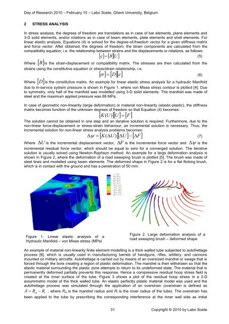
is the c<strong>on</strong>stitutive matrix. An example for linear elastic stress analysis for a hydraulic Manifold<br />
due to in-service system pressure is shown in Figure 1, where v<strong>on</strong> Mises stress c<strong>on</strong>tour is plotted [4]. Due<br />
to symmetry, <strong>on</strong>ly half of the manifold was modelled using 3-D solid elements. The manifold was made of<br />
steel <strong>and</strong> the maximum applied pressure was 68 MPa.<br />
In case of geometric n<strong>on</strong>-linearity (large deformati<strong>on</strong>) or material n<strong>on</strong>-linearity (elastic-plastic), the stiffness<br />
matrix becomes functi<strong>on</strong> of the unknown degrees of freedom so that Equati<strong>on</strong> (4) becomes:<br />
K(<br />
U)<br />
U<br />
F<br />
The soluti<strong>on</strong> cannot be obtained in <strong>on</strong>e step <strong>and</strong> an iterative soluti<strong>on</strong> is required. Furthermore, due to the<br />
n<strong>on</strong>-linear force-displacement or stress-strain behaviour, an incremental soluti<strong>on</strong> is necessary. Thus, the<br />
incremental soluti<strong>on</strong> for n<strong>on</strong>-linear stress analysis problems becomes:<br />
K(<br />
U<br />
) U<br />
F<br />
(7)<br />
<br />
U<br />
is the incremental displacement vector, F<br />
is the incremental force vector <strong>and</strong> <br />
Where<br />
is the<br />
incremental residual force vector, which should be equal to zero for a c<strong>on</strong>verged soluti<strong>on</strong>. The iterative<br />
soluti<strong>on</strong> is usually solved using Newt<strong>on</strong>-Raphs<strong>on</strong> method. An example for a large deformati<strong>on</strong> analysis is<br />
shown in Figure 2, where the deformati<strong>on</strong> of a road sweeping brush is plotted [5]. The brush was made of<br />
steel tines <strong>and</strong> modelled using beam elements. The deformed shape in Figure 2 is for a flat flicking brush,<br />
which is in c<strong>on</strong>tact with the ground <strong>and</strong> has a penetrati<strong>on</strong> of 50 mm.<br />
Figure 1. Linear elastic analysis of a<br />
Hydraulic Manifold – v<strong>on</strong> Mises stress (MPa)<br />
Figure 2. Large deformati<strong>on</strong> analysis of a<br />
road sweeping brush – deformed shape<br />
An example of material n<strong>on</strong>-linearity finite element modelling is a thick walled tube subjected to autofrettage<br />
process [6], which is usually used in manufacturing barrels of h<strong>and</strong>guns, rifles, artillery, <strong>and</strong> cann<strong>on</strong>s<br />
mounted <strong>on</strong> military aircrafts. Autofrettage is carried out by means of an oversized m<strong>and</strong>rel or swage that is<br />
forced through the bore creating a regi<strong>on</strong> of plastic deformati<strong>on</strong>. The m<strong>and</strong>rel is then withdrawn so that the<br />
elastic material surrounding the plastic z<strong>on</strong>e attempts to return to its undeformed state. The material that is<br />
permanently deformed partially prevents this resp<strong>on</strong>se. Hence a compressive residual hoop stress field is<br />
created at the inner surface of the tube. Figure 3 shows a plot of the residual hoop stress in a 2-D<br />
axsymmetric model of the thick walled tube. An elastic perfectly plastic material model was used <strong>and</strong> the<br />
autofrettage process was simulated through the applicati<strong>on</strong> of an overstrain (overstrain is defined as<br />
R , where R m is the m<strong>and</strong>rel radius <strong>and</strong> R i is the inner radius of the tube). The overstrain has<br />
m<br />
R i<br />
been applied to the tube by prescribing the corresp<strong>on</strong>ding interference at the inner wall side as initial<br />
31 Copyright © 2010 by Labo Soete