F - 5th International Conference on Sustainable Construction and ...
F - 5th International Conference on Sustainable Construction and ...
F - 5th International Conference on Sustainable Construction and ...

You also want an ePaper? Increase the reach of your titles
YUMPU automatically turns print PDFs into web optimized ePapers that Google loves.
Day of Research 2010 – February 10 – Labo Soete, Ghent University, Belgium<br />
5 COUPLED-FIELD ANALYSIS<br />
A coupled-field analysis, also known as multi-physics analysis, is a combinati<strong>on</strong> of two or more dependent<br />
analyses from different physics field. The output of <strong>on</strong>e analysis would be the input for the next analysis.<br />
For example, after performing heat transfer analysis, the temperature distributi<strong>on</strong> would generate thermal<br />
strains, which can be applied to a subsequent stress analysis. We present herein two examples of coupled<br />
field analysis, namely thermal-stress analysis <strong>and</strong> diffusi<strong>on</strong>-stress analysis. The steps that are involved in<br />
performing the coupled field analyses are summarised in Figure 6(a). The same finite element mesh should<br />
be used for both heat transfer <strong>and</strong> stress analyses. However, the element type should be switched from<br />
heat transfer element to structural element. If the mechanical properties are thermal or moisture dependent,<br />
they have to be defined for each element according to its temperature or moisture c<strong>on</strong>centrati<strong>on</strong>. The<br />
thermal strains ( <br />
t<br />
T<br />
, where is the coefficient of thermal expansi<strong>on</strong> <strong>and</strong> T T T<br />
with<br />
ref<br />
T the<br />
calculated temperature <strong>and</strong> T a reference or strain free temperature) or swelling strains ( c<br />
,<br />
ref<br />
where is the coefficient of swelling <strong>and</strong> c is the moisture c<strong>on</strong>centrati<strong>on</strong>) are calculated for each element.<br />
s<br />
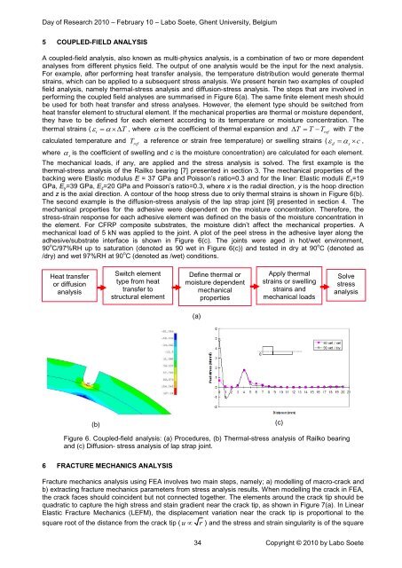
The mechanical loads, if any, are applied <strong>and</strong> the stress analysis is solved. The first example is the<br />
thermal-stress analysis of the Railko bearing [7] presented in secti<strong>on</strong> 3. The mechanical properties of the<br />
backing were Elastic modulus E = 37 GPa <strong>and</strong> Poiss<strong>on</strong>’s ratio=0.3 <strong>and</strong> for the liner: Elastic modulii E x =19<br />
GPa, E y =39 GPa, E z =20 GPa <strong>and</strong> Poiss<strong>on</strong>’s ratio=0.3, where x is the radial directi<strong>on</strong>, y is the hoop directi<strong>on</strong><br />
<strong>and</strong> z is the axial directi<strong>on</strong>. A c<strong>on</strong>tour of the hoop stress due to <strong>on</strong>ly thermal strains is shown in Figure 6(b).<br />
The sec<strong>on</strong>d example is the diffusi<strong>on</strong>-stress analysis of the lap strap joint [9] presented in secti<strong>on</strong> 4. The<br />
mechanical properties for the adhesive were dependent <strong>on</strong> the moisture c<strong>on</strong>centrati<strong>on</strong>. Therefore, the<br />
stress-strain resp<strong>on</strong>se for each adhesive element was defined <strong>on</strong> the basis of the moisture c<strong>on</strong>centrati<strong>on</strong> in<br />
the element. For CFRP composite substrates, the moisture didn’t affect the mechanical properties. A<br />
mechanical load of 5 kN was applied to the joint. A plot of the peel stress in the adhesive layer al<strong>on</strong>g the<br />
adhesive/substrate interface is shown in Figure 6(c). The joints were aged in hot/wet envir<strong>on</strong>ment,<br />
90 o C/97%RH up to saturati<strong>on</strong> (denoted as 90 wet in Figure 6(c)) <strong>and</strong> tested in dry at 90 o C (denoted as<br />
/dry) <strong>and</strong> wet 97%RH at 90 o C (denoted as /wet) c<strong>on</strong>diti<strong>on</strong>s.<br />
d<br />
s<br />
Heat transfer<br />
or diffusi<strong>on</strong><br />
analysis<br />
Switch element<br />
type from heat<br />
transfer to<br />
structural element<br />
Define thermal or<br />
moisture dependent<br />
mechanical<br />
properties<br />
Apply thermal<br />
strains or swelling<br />
strains <strong>and</strong><br />
mechanical loads<br />
Solve<br />
stress<br />
analysis<br />
(a)<br />
(b)<br />
(c)<br />
Figure 6. Coupled-field analysis: (a) Procedures, (b) Thermal-stress analysis of Railko bearing<br />
<strong>and</strong> (c) Diffusi<strong>on</strong>- stress analysis of lap strap joint.<br />
6 FRACTURE MECHANICS ANALYSIS<br />
Fracture mechanics analysis using FEA involves two main steps, namely; a) modelling of macro-crack <strong>and</strong><br />
b) extracting fracture mechanics parameters from stress analysis results. When modelling the crack in FEA,<br />
the crack faces should coincident but not c<strong>on</strong>nected together. The elements around the crack tip should be<br />
quadratic to capture the high stress <strong>and</strong> stain gradient near the crack tip, as shown in Figure 7(a). In Linear<br />
Elastic Fracture Mechanics (LEFM), the displacement variati<strong>on</strong> near the crack tip is proporti<strong>on</strong>al to the<br />
square root of the distance from the crack tip ( u r ) <strong>and</strong> the stress <strong>and</strong> strain singularity is of the square<br />
34 Copyright © 2010 by Labo Soete