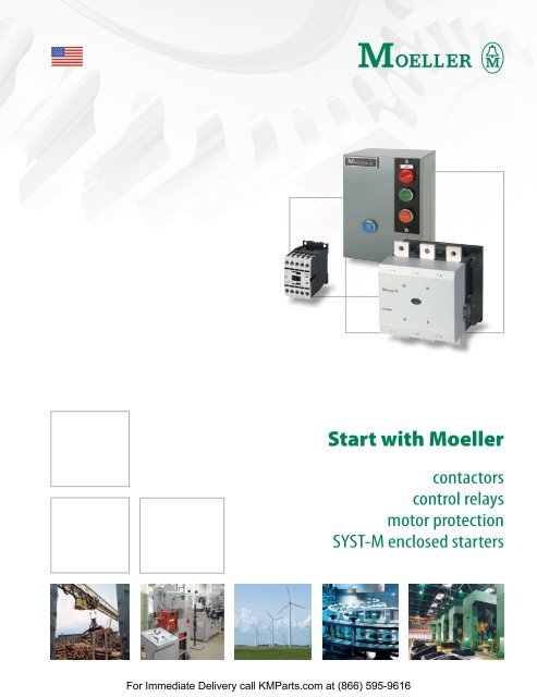
Start with Moeller - Klockner Moeller Parts
Start with Moeller - Klockner Moeller Parts
Start with Moeller - Klockner Moeller Parts

You also want an ePaper? Increase the reach of your titles
YUMPU automatically turns print PDFs into web optimized ePapers that Google loves.
For Immediate Delivery call KM<strong>Parts</strong>.com at (866) 595-9616<br />
<strong>Start</strong> <strong>with</strong> <strong>Moeller</strong><br />
contactors<br />
control relays<br />
motor protection<br />
SYST-M enclosed starters
contactors<br />
General Information ................................................................. A2<br />
DIL M Contactors (7 – 1000 Amps) ........................................ A8<br />
Miniature Contactors ............................................................... A11<br />
Four-pole Contactors ................................................................ A13<br />
Reversing Contactor Combinations ...................................... A14<br />
Capacitor Switching Contactors ............................................ A15<br />
NEMA Contactors ...................................................................... A16<br />
Accessories .................................................................................. A17<br />
Replacement Coils ..................................................................... A32<br />
Contact Travel Diagrams ......................................................... A34<br />
Utilization Curves ...................................................................... A36<br />
Technical Data ........................................................................... A40<br />
Dimensions ................................................................................. A76<br />
For Immediate Delivery call KM<strong>Parts</strong>.com at (866) 595-9616<br />
A<br />
Contactors
A<br />
Contactors<br />
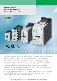
series DIL M contactors<br />
reliable switching for applications up to 1000A<br />
R<br />
> 24 contactors<br />
> 7 frame sizes<br />
> Switches motors up to 1000HP<br />
> Same compact dimensions<br />
for AC and DC units<br />
A2<br />
<strong>Moeller</strong>’s DIL M contactor line packs all the control you need into a smart, compact<br />
design. Our modern IEC contactors can handle up to 1000A in virtually any application<br />
worldwide. Their compliance <strong>with</strong> IEC standards ensures the most accurate<br />
match to your motor size – you’ll never buy more control than you need.<br />
For a broad range of applications<br />
Twenty-four contactors in seven frame sizes cover all applications from fractional<br />
to 1000HP (@ 575V). This extensive range allows you to select exactly the right<br />
size for your application, whether it be resistive AC-1 environments; common<br />
starting and stopping AC-3 applications; or even extreme AC-4 situations involving<br />
inching and plugging of motors.<br />
Easy installation by design<br />
The DIL M contactor series features dual power terminals on units up to 400A. The<br />
clamping chambers are cleverly designed to apply<br />
sufficient holding pressure to cables of varying sizes.<br />
Conventional designs are often limited by the size of<br />
the largest cable in the chamber.<br />
The line also features ingenious mechanical interlocks<br />
(rocker and ball style) that allow fast and easy<br />
assembly of contactor combinations <strong>with</strong>out requiring<br />
additional space. Many contactors can be interlocked<br />
both horizontally and vertically.<br />
Accessories extend flexibility<br />
Several ranges <strong>with</strong>in the DIL M series share common auxiliary contacts and other<br />
components. This lowers inventories even when accommodating a complete<br />
range of control solutions. Voltage indicators, reversing kits, and many other optional<br />
accessories are also available.<br />
Safety<br />
All DIL M series contactors provide isolation and protection from direct hand contact.<br />
Even the largest contactors accept terminal shields.<br />
For Immediate Delivery call KM<strong>Parts</strong>.com at (866) 595-9616
DIL M Low Range<br />
<strong>Moeller</strong>’s DIL M contactor series includes a completely<br />
NEW offering in the lower 7 to 150A range. Consisting<br />
of four frame sizes, this range is the newest and most<br />
modern of any control manufacturer!<br />
Compact<br />
design for BOTH<br />
currents<br />
Conventional contactors<br />
designed for DC control<br />
applications can be up<br />
to 30% larger than their<br />
AC counterparts. Not<br />
anymore! Unique to <strong>Moeller</strong>’s DIL M contactors, AC and<br />
DC units are the same frame size throughout the entire<br />
range. The reduced size means smaller DC panels than<br />
ever before. This also means you can now design one<br />
panel for either AC or DC control, <strong>with</strong>out having to plan<br />
for a larger DC contactor.<br />
Easy to assemble<br />
Coil terminals are located on the front of the new contactors<br />
to simplify wiring. Both<br />
two and four-pole auxiliary contacts<br />
snap on <strong>with</strong>out tools. Units<br />
40A and above accept both side<br />
and top mount auxiliaries for increased<br />
flexibility. In addition, devices up to 32A include<br />
built-in auxiliary contacts for increased economy <strong>with</strong><br />
no additional space requirement.<br />
Contacts designed for safety<br />
Auxiliary contact blocks for new DIL M contactors have<br />
positively guided contacts for added safety in control<br />
circuits. Positively guided auxiliary contacts insure that,<br />
throughout the life of the contactor, NO and NC contacts<br />
will never close simultaneously…even if a contact<br />
welds. In addition, DIL M contactors to 65A have “mirror”<br />
contacts, which ensure that all auxiliary contacts<br />
(whether built-in or add-on) function correctly in relation<br />
to the power contacts.<br />
Special advantages of going DC<br />
In addition to sharing the same frame size as AC contactors,<br />
DC units of 17A and above also feature electronic<br />
drives that dramatically reduce pick-up and sealing consumption.<br />
These drives produce several benefits:<br />
• less heat is generated, eliminating the<br />
need for a fan<br />
• smaller control transformers are required<br />
• contactors up to DIL M32 can be directly<br />
actuated from PLCs, eliminating the need for<br />
a coupling relay<br />
These benefits lower your cost by consuming less power,<br />
eliminating additional components, and permitting<br />
higher packing density in the panel.<br />
DC units to 150A also carry a built-in high-speed suppressor<br />
circuit, eliminating the need for purchasing and<br />
installing a separate external suppressor. Again, lower<br />
total cost and smaller panel space result.<br />
For additional safety and convenience, <strong>Moeller</strong>’s DIL M<br />
DC contactors feature an expanded voltage tolerance,<br />
beyond that specified by IEC/EN 60947. This accommodates<br />
a range of -30% to +20% for DIL M contactors<br />
17A and above. It is one of the largest voltage tolerance<br />
ranges of any control manufacturer.<br />
For Immediate Delivery call KM<strong>Parts</strong>.com at (866) 595-9616<br />
+20%<br />
-30%<br />
A3<br />
A<br />
Contactors
A<br />
Contactors<br />
A4<br />
DIL M High Range<br />
For heavy-duty applications, <strong>Moeller</strong>’s contactor line<br />
continues <strong>with</strong> the DIL M185 to DIL M1000. This range<br />
includes 11 contactors in three frame sizes. All applications<br />
and worldwide voltages, both AC and DC, can be<br />
accommodated <strong>with</strong> only four coils.<br />
On-board electronics<br />
for efficient operation<br />
All DIL M185 to 1000 contactors utilize electronicallycontrolled<br />
magnet systems. This feature provides flexible<br />
actuation, and contributes to lower panel temperature,<br />
smaller control transformer requirements<br />
and greater control voltage tolerance. Direct actuation<br />
from a PLC or other low level source is easily accomplished.<br />
In addition, a built-in suppressor circuit for<br />
control protection is standard. All of this adds up to<br />
fewer external components and smaller panel space.<br />
Vacuum contactors<br />
designed for small size, long life<br />
DIL M580 to DIL M1000 are vacuum contactors. This<br />
feature reduces contact damage caused by electrical<br />
arcing, leading to longer life of the contactor. It also<br />
permits tighter packing density in the panel because<br />
there are no open arcs or escaping gases that would<br />
typically require additional space for dissipation.<br />
DIL EM<br />
Miniature Contactors<br />
<strong>Moeller</strong> also offers a miniature contactor, the DIL EM.<br />
Designed for small loads, it is available in units up to<br />
20A, and provides reliable performance for motors up<br />
to 5HP (@575V). AC and DC units are available.<br />
The DIL EM miniature contactor features a large ambient<br />
temperature range, and its low power consumption<br />
permits direct actuation from a PLC. The DC version<br />
of the DIL EM also includes an integrated suppressor to<br />
protect from voltage peaks that may occur when the<br />
coil is disconnected. Top-mount auxiliary contacts are<br />
available in both 2- and 4-pole configurations.<br />
Standards and Approvals<br />
<strong>Moeller</strong>’s DIL M and DIL EM contactors carry UL, CSA,<br />
IEC/EN 60947 and VDE 0660 approvals. They are manufactured<br />
to ISO 9001 quality standards.<br />
For Immediate Delivery call KM<strong>Parts</strong>.com at (866) 595-9616
<strong>Moeller</strong>’s catalog numbering system for contactors and other devices<br />
follows a logical system. Device attributes can be determined by the<br />
following nomenclature.<br />
DIL<br />
DIUL<br />
M<br />
EM<br />
MP<br />
K<br />
M-*N<br />
7<br />
↓<br />
1000<br />
Product Line<br />
Non-reversing contactors<br />
Reversing contactors<br />
Contactor Type<br />
Contactors<br />
Miniature contactors<br />
4-pole contactors<br />
Capacitor switching contactors<br />
NEMA rated contactors<br />
Contactor Size<br />
<strong>Moeller</strong> contactors are available in 24<br />
sizes ranging from 7 to 1000 A<br />
Dashes (–) are used to separate device attributes and should always<br />
be included when ordering.<br />
DIL M 7 – 10 (240V60Hz)<br />
Coil Voltage<br />
(values shown are for illustration purposes only -<br />
more voltages available)<br />
(240V60Hz)<br />
(24VDC)<br />
(RA250)<br />
(RDC24)<br />
Auxiliary Contacts<br />
(these characters only appear when Auxiliary Contacts<br />
are integrated into the base contactor)<br />
STARTER-CAT-USA-1206 moellerNA.com A5<br />
10<br />
01<br />
22<br />
Standard electromechanical<br />
AC coil of 240V / 60Hz<br />
Standard electromechanical<br />
DC coil of 24V<br />
Electronic AC coil of 110-250V<br />
50/60Hz<br />
Electronic DC coil of 24V<br />
1 Normally Open - No Normally Closed<br />
No Normally Open - 1 Normally Open<br />
2 Normally Open - 2 Normally Closed<br />
This page for reference only.<br />
Please turn to the appropriate pages to determine<br />
the exact device and/or accessories required for your application.<br />
For Immediate Delivery call KM<strong>Parts</strong>.com at (866) 595-9616<br />
Contactor Nomenclature<br />
Series DIL M Contactors<br />
A<br />
Contactors
A<br />
Contactors<br />
Frame Size<br />
<strong>Moeller</strong><br />
Contactor<br />
➊ DILM17 does not meet <strong>with</strong> NEMA size 1 switching duty.<br />
Maximum Horsepower (UL/CSA)<br />
Single Phase Three Phase<br />
115 Volt 230 Volt 200 Volt 230 Volt 460 Volt 575 Volt<br />
DIL M7 ¼ 1 1½ 2 3 5<br />
1 /3 1 1½ 1½ 2 2 NEMA Size 00<br />
DIL M9 ½ 1½ 3 3 5 7½<br />
<strong>Moeller</strong> Contactor Family<br />
Equivalent NEMA sizes<br />
1 2 3 3 5 5 NEMA Size 0<br />
DIL M12 1 2 3 3 10 10<br />
DIL M17 ➊ 2 3 7½ 7½ 10 15<br />
2 3 7½ 7½ 10 10 NEMA Size 1<br />
DIL M25 2 5 7½ 10 15 20<br />
DIL M32 3 5 10 10 20 25<br />
3 7½ 10 15 25 25 NEMA Size 2<br />
DIL M40 3 7½ 10 15 30 40<br />
DIL M50 3 10 15 20 40 50<br />
DIL M65 5 15 20 25 50 60<br />
7½ 15 25 30 50 50 NEMA Size 3<br />
DIL M80 7½ 15 25 30 60 75<br />
DIL M95 7½ 15 25 40 75 100<br />
– – 40 50 100 100 NEMA Size 4<br />
DIL M115 10 25 40 50 100 100<br />
DIL M150 15 30 40 60 125 125<br />
DIL M185 – – 50 60 125 150<br />
DIL M225 – – 60 75 150 200<br />
– – 75 100 200 200 NEMA Size 5<br />
DIL M250 – – 75 100 200 250<br />
DIL M300 – – 100 125 250 300<br />
DIL M400 – – 125 150 300 400<br />
– – 150 200 400 400 NEMA Size 6<br />
DIL M500 – – 150 200 400 500<br />
DIL M580 – – 200 200 400 600<br />
DIL M650 – – 200 250 500 600<br />
– – – 300 600 600 NEMA Size 7<br />
DIL M750 – – 250 300 600 700<br />
DIL M820 – – 290 350 700 860<br />
– – – 450 900 900 NEMA Size 8<br />
DIL M1000 – – – 400 800 1000<br />
A6 moellerNA.com STARTER-CAT-USA-1206<br />
For Immediate Delivery call KM<strong>Parts</strong>.com at (866) 595-9616<br />
Compare <strong>Moeller</strong>’s 24 contactor sizes to just 10 equivalent NEMA sizes
The full-load current values listed in the table below are for motors<br />
running at usual speeds, <strong>with</strong> normal torque characteristics at 1.15<br />
service factor. This table is a guide only. The actual full load motor<br />
amps for your motor may be different than the average values<br />
listed here. Always use the actual motor current listed on the motor<br />
nameplate when purchasing motor control and protection products.<br />
Motor<br />
Rating (HP)<br />
115 V<br />
AC Induction Motor – Full Load Current (A)<br />
Single Phase Three Phase<br />
200 V 230 V 200 V 230 V 460 V 575 V<br />
1/6 4.4 2.5 2.2 – – – –<br />
1/4 5.8 3.3 2.9 – – – –<br />
1/3 7.2 4.1 3.6 – – – –<br />
1/2 9.8 5.6 4.9 2.3 2.0 1.0 0.8<br />
3/4 13.8 7.9 6.9 3.2 2.8 1.4 1.1<br />
1 16 9.2 8 4.1 3.6 1.8 1.4<br />
1-1/2 20 11.5 10 6.0 5.2 2.6 2.1<br />
2 24 13.8 12 7.8 6.8 3.4 2.7<br />
3 34 19.6 17 11.0 9.6 4.8 3.9<br />
5 56 32.2 28 17.5 15.2 7.6 6.1<br />
7-1/2 80 46 40 25.3 22 11 9<br />
10 100 57.5 50 32.2 28 14 11<br />
15 – – – 48.3 42 21 17<br />
20 – – – 62.1 54 27 22<br />
25 – – – 78.2 68 34 27<br />
30 – – – 92.0 80 40 32<br />
40 – – – 119.6 104 52 41<br />
50 – – – 149.5 130 65 52<br />
60 – – – 177.1 154 77 62<br />
75 – – – 220.8 192 96 77<br />
100 – – – 285.2 248 124 99<br />
125 – – – 358.8 312 156 125<br />
150 – – – 414 360 180 144<br />
200 – – – 552 480 240 192<br />
300 – – – 825 720 360 288<br />
350 – – – 963 840 420 336<br />
400 – – – 1100 960 480 384<br />
450 – – – 1238 1080 540 432<br />
500 – – – 1375 1200 600 480<br />
600 – – – 1650 1440 720 576<br />
700 – – – 1925 1680 840 672<br />
800 – – – 2200 1920 960 768<br />
900 – – – 2475 2160 1080 864<br />
1000 – – – 2750 2400 1200 960<br />
NOTE: This chart was developed from Table 430-148 & 430-150 of the NEC, Table 52.2 of UL standard 508 and<br />
from the Canadian Electrical Code (CEC), Part 1, table 44 and 45.<br />
STARTER-CAT-USA-1206 moellerNA.com A7<br />
For Immediate Delivery call KM<strong>Parts</strong>.com at (866) 595-9616<br />
Motor Current Rating Chart<br />
According to NEC and CEC<br />
A<br />
Contactors
A<br />
Contactors<br />
> Four compact frame sizes cover applications to 150A<br />
> Space-saving design reduces panel space and cost<br />
> Dual box terminals make wiring safer and easier for cables <strong>with</strong><br />
uneven cross-sections<br />
> New combination plug-in technology provides tool-less<br />
connection <strong>with</strong> other starting components up to DIL M12<br />
Three-pole Contactors <strong>with</strong> AC Coil (to 150 Amps) ➊➋<br />
Maximum UL / CSA Horsepower Ratings Auxiliary<br />
General Use<br />
(A)<br />
Single Phase Three Phase<br />
Contacts<br />
Open Enclosed 115 V 200 V 230 V 200 V 230 V 460 V 575 V NO NC<br />
20 18 1/4 3/4 1 1½ 2 3 5<br />
20 18 1/2 1 1½ 3 3 5 7½<br />
20 18 1 2 2 3 3 10 10<br />
40 36 2 2 3 5 5 10 15<br />
40 36 2 3 5 7½ 7½ 15 20<br />
40 36 3 5 5 10 10 20 25<br />
Catalog Number Price<br />
1 0 DILM7-10◆ ➌ 88<br />
0 1 DILM7-01◆ ➌ 88<br />
1 0 DILM9-10◆ ➌ 100<br />
0 1 DILM9-01◆ ➌ 100<br />
1 0 DILM12-10◆ ➌ 124<br />
0 1 DILM12-01◆ ➌ 124<br />
1 0 DILM17-10◆ 130<br />
0 1 DILM17-01◆ 130<br />
1 0 DILM25-10◆ 175<br />
0 1 DILM25-01◆ 175<br />
1 0 DILM32-10◆ 220<br />
0 1 DILM32-01◆ 220<br />
55 49 3 5 7½ 10 15 30 40 0 0 DILM40◆ ➍ 250<br />
65 58 3 7½ 10 15 20 40 50 0 0 DILM50◆ ➍ 290<br />
80 72 5 10 15 20 25 50 60 0 0 DILM65◆ ➍ 390<br />
125 112 7½ 15 15 25 30 60 75 0 0 DILM80◆ ➍ 480<br />
125 112 7½ 15 15 25 40 75 100 0 0 DILM95◆ ➍ 595<br />
155 140 10 25 25 40 50 100 100 0 0 DILM115◆ ➍ 820<br />
155 140 15 25 30 40 60 125 125 0 0 DILM150◆ ➍ 1010<br />
Ordering Instructions<br />
1<br />
Locate the<br />
desired<br />
contactor<br />
2<br />
Complete<br />
catalog<br />
number by<br />
adding coil<br />
code<br />
3<br />
See pages<br />
A17 - A30 for<br />
auxiliaries &<br />
accessories<br />
➊ Positively guided contacts <strong>with</strong>in all auxiliary contact modules (including any<br />
internal auxiliaries). Mirror contacts on all contactors (in relation to internal or<br />
external auxiliaries).<br />
➋ Contact elements of the contactor to EN 50012.<br />
➌ Coils not replaceable.<br />
AC Coil Codes - DILM7 – 95 ➎<br />
Complete catalog Voltage Range<br />
number (◆) <strong>with</strong>… 50 Hz 60Hz<br />
(24V60Hz) – 24V<br />
(120V60Hz) 110V 120V<br />
(208V60Hz) – 208V<br />
(220V60Hz) 190V 220V<br />
(240V60Hz) 230V 240V<br />
(480V60Hz) 415V 480V<br />
(600V60Hz) – 600V<br />
Contactors (to 150 amps)<br />
AC Coil Codes - DILM115 – 150<br />
Complete catalog Voltage Range<br />
number (◆) <strong>with</strong>… 50/60 Hz<br />
(RAC24) 24V<br />
(RAC120) 120V<br />
(RAC240) 190V – 240V<br />
(RAC500) 480V – 500V<br />
➍ May combine side mount and front mount auxiliary contact modules. Up to six<br />
auxiliary contacts possible.<br />
➎ Other coil voltages between 24 and 600V AC available by special order.<br />
Contact your <strong>Moeller</strong> representative for information.<br />
A8 moellerNA.com Discount Schedule A20<br />
STARTER-CAT-USA-1206<br />
For Immediate Delivery call KM<strong>Parts</strong>.com at (866) 595-9616<br />
AC Coil
Same compact size as <strong>Moeller</strong>’s AC contactors, saving panel space<br />
> Electronically controlled magnet system (from DIL M17) provides<br />
less heat dissipation and smaller control transformers<br />
> Direct actuation from a PLC <strong>with</strong>out coupling relays<br />
(DIL M17 to 32)<br />
> Integrated surge suppressor<br />
Three-pole Contactors <strong>with</strong> DC Coil (to 150 Amps) ➊➋➌<br />
Maximum UL / CSA Horsepower Ratings Auxiliary<br />
General Use<br />
(A)<br />
Single Phase Three Phase<br />
Contacts<br />
Open Enclosed 115 V 200 V 230 V 200 V 230 V 460 V 575 V NO NC<br />
20 18 1/4 3/4 1 1½ 2 3 5<br />
20 18 1/2 1 1½ 3 3 5 7½<br />
20 18 1 2 2 3 3 10 10<br />
40 36 2 2 3 5 5 10 15<br />
40 36 2 3 5 7½ 7½ 15 20<br />
40 36 3 5 5 10 10 20 25<br />
Catalog Number Price<br />
1 0 DILM7-10◆ ➍ 110<br />
0 1 DILM7-01◆ ➍ 110<br />
1 0 DILM9-10◆ ➍ 120<br />
0 1 DILM9-01◆ ➍ 120<br />
1 0 DILM12-10◆ ➍ 158<br />
0 1 DILM12-01◆ ➍ 158<br />
1 0 DILM17-10◆ 185<br />
0 1 DILM17-01◆ 185<br />
1 0 DILM25-10◆ 225<br />
0 1 DILM25-01◆ 225<br />
1 0 DILM32-10◆ 310<br />
0 1 DILM32-01◆ 310<br />
55 49 3 5 7½ 10 15 30 40 0 0 DILM40◆ ➎ 325<br />
65 58 3 7½ 10 15 20 40 50 0 0 DILM50◆ ➎ 460<br />
80 72 5 10 15 20 25 50 60 0 0 DILM65◆ ➎ 585<br />
125 112 7½ 15 15 25 30 60 75 0 0 DILM80◆ ➎ 650<br />
125 112 7½ 15 15 25 40 75 100 0 0 DILM95◆ ➎ 775<br />
155 140 10 25 25 40 50 100 100 0 0 DILM115◆ ➎ 925<br />
155 140 15 25 30 40 60 125 125 0 0 DILM150◆ ➎ 1196<br />
Ordering Instructions<br />
1<br />
Locate the<br />
desired<br />
contactor<br />
2<br />
Complete<br />
catalog<br />
number by<br />
adding coil<br />
code<br />
3<br />
See pages<br />
A17 - A30 for<br />
auxiliaries &<br />
accessories<br />
➊ Positively guided contacts <strong>with</strong>in all auxiliary contact modules (including any<br />
internal auxiliaries). Mirror contacts on all contactors (in relation to internal or<br />
external auxiliaries).<br />
➋ Contact elements of the contactor to EN 50012.<br />
➌ DC-operated contactors have an integrated surge suppressor.<br />
DC Coil Codes - DILM7 – 12 ➏<br />
Complete catalog<br />
number (◆) <strong>with</strong>… Voltage<br />
(24VDC) 24V<br />
(48VDC) 48V<br />
Contactors (to 150 amps)<br />
DC Coil Codes - DILM17 – 150 ➏<br />
Complete catalog<br />
number (◆) <strong>with</strong>… Voltage Range<br />
(RDC24) 24 – 27V DC<br />
(RDC60) 48 – 60V DC<br />
(RDC130) 110 – 130V DC<br />
(RDC240) 200 – 240V DC<br />
➍ Coils not replaceable.<br />
➎ May combine side mount and front mount auxiliary contact modules. Up to six<br />
auxiliary contacts possible.<br />
➏ Other coil voltages between 12 and 250V DC available by special order.<br />
Contact your <strong>Moeller</strong> representative for information.<br />
STARTER-CAT-USA-1206 Discount Schedule A20<br />
moellerNA.com A9<br />
For Immediate Delivery call KM<strong>Parts</strong>.com at (866) 595-9616<br />
DC Coil<br />
A<br />
Contactors
A<br />
Contactors<br />
> Heavy duty contactors for demanding applications<br />
> Electronically controlled magnet systems dramatically reduce<br />
pick-up and seal-in, while increasing control voltage tolerance<br />
> Direct connection to PLCs and low level input devices<br />
> Large HP devices (from DIL M580) are vacuum contactors, which<br />
increase electrical lifespan and decrease space requirements<br />
> Built-in suppressor circuit for control protection<br />
Three-pole Contactors <strong>with</strong> AC or DC Electronic Coil (185 to 1000 Amps) ➊<br />
General Use<br />
(A)<br />
Maximum UL / CSA<br />
Horsepower Ratings<br />
Three Phase<br />
Auxiliary<br />
Contacts<br />
Open Enclosed 200 V 230 V 460 V 575 V NO NC<br />
Catalog Number Price<br />
225 202 50 60 125 150 2 2 DILM185/22◆ 1800<br />
250 225 60 75 150 200 2 2 DILM225/22◆ 2200<br />
350 315 75 100 200 250 2 2 DILM250/22◆ 2800<br />
350 315 100 125 250 300 2 2 DILM300/22◆ 3100<br />
450 405 100 150 300 400 2 2 DILM400/22◆ 3900<br />
550 495 150 200 400 500 2 2 DILM500/22◆ 5800<br />
630 567 200 200 400 600 2 2 DILM580/22◆ ➋ 7400<br />
700 630 200 250 500 600 2 2 DILM650/22◆ ➋ 7900<br />
800 720 250 300 600 700 2 2 DILM750/22◆ ➋ 9100<br />
850 765 290 350 700 860 2 2 DILM820/22◆ ➋ 10100<br />
1000 900 – 400 800 1000 2 2 DILM1000/22◆ ➋ 11700<br />
AC & DC Coil Codes ➍<br />
Complete catalog<br />
number (◆) <strong>with</strong>… Voltage<br />
(RDC48)<br />
24 – 48V DC<br />
(only for DILM185 – 500)<br />
(RA110)<br />
48 – 110V AC<br />
48 – 110V DC<br />
(RA250)<br />
110 – 250V AC<br />
110 – 250V DC<br />
(RAC500) 250 – 500V AC<br />
Ordering Instructions<br />
1<br />
Locate the<br />
desired<br />
contactor<br />
2<br />
Complete<br />
catalog<br />
number by<br />
adding coil<br />
code<br />
3<br />
See pages<br />
A17 - A30 for<br />
auxiliaries &<br />
accessories<br />
4<br />
See page<br />
A29 for<br />
terminal lug<br />
selections<br />
Electronic Coil - Application Notes<br />
Conventional coil connection<br />
A1/A2 are applied to voltage in the usual manner.<br />
Direct from the PLC<br />
A 24 V output from the PLC can be connected directly to<br />
connections A3/A4.<br />
From low-consumption command devices<br />
Command devices that can only be subject to minimal<br />
loads such as circuit board relays, control circuit devices<br />
or position switches can be connected directly to<br />
A10/A11.<br />
(+) L1<br />
(–) N<br />
➊ Do not reverse contactors directly.<br />
➋ When operating <strong>with</strong> frequency inverters or when performing a high-voltage test,<br />
the suppressor on the load side must be removed.<br />
➌ Standstill in an emergency (emergency stop).<br />
➍ Wide range electronic coils; all AC coils operate between 40Hz and 60Hz.<br />
A10 moellerNA.com Discount Schedule A20<br />
STARTER-CAT-USA-1206<br />
(+) L1<br />
(–) N<br />
(+) L1<br />
(–) N<br />
A10<br />
A11<br />
24 V<br />
GND<br />
For Immediate Delivery call KM<strong>Parts</strong>.com at (866) 595-9616<br />
Contactors (185 to 1000 amps)<br />
A10<br />
A11<br />
A2<br />
A1<br />
A3<br />
A4<br />
A2<br />
A1<br />
A3<br />
A4<br />
A10<br />
A11<br />
A2<br />
A1<br />
A3<br />
A4<br />
➌<br />
➌<br />
AC & DC Coil<br />
➌
Miniature, economical contactors for small motors and loads<br />
> Approved for worldwide use<br />
> High degree of climatic approvals and large ambient<br />
temperature range<br />
> AC and DC operated versions available<br />
> DC model includes integrated diode/resistor surge suppressor<br />
Miniature Three-pole Contactors <strong>with</strong> AC Coil ➊<br />
General Use<br />
(A)<br />
Maximum UL / CSA Horsepower Ratings Auxiliary<br />
Single Phase Three Phase<br />
Contacts<br />
Open Enclosed 115 V 200 V 230 V 200 V 230 V 460 V 575 V NO NC<br />
Catalog Number Price<br />
15 13.5 1/2 1 1½ 2 3 5 5 1 0 DILEM-10◆ 72<br />
15 13.5 1/2 1 1½ 2 3 5 5 0 1 DILEM-01◆ 72<br />
Miniature Three-pole Contactors <strong>with</strong> DC Coil ➊➋<br />
General Use<br />
(A)<br />
Maximum UL / CSA Horsepower Ratings Auxiliary<br />
Single Phase Three Phase<br />
Contacts<br />
Open Enclosed 115 V 200 V 230 V 200 V 230 V 460 V 575 V NO NC<br />
Catalog Number Price<br />
15 13.5 1/2 1 1½ 2 3 5 5 1 0 DILEM-10-G◆ 90<br />
15 13.5 1/2 1 1½ 2 3 5 5 0 1 DILEM-01-G◆ 90<br />
AC Coil Codes ➊<br />
Complete catalog<br />
number (◆) <strong>with</strong>…<br />
Voltage Range<br />
50 Hz 60Hz<br />
(24V60Hz) – 24V<br />
(120V60Hz) 110V 120V<br />
(208V60Hz) – 208V<br />
(220V60Hz) 190V 220V<br />
(240V60Hz) 230V 240V<br />
(480V60Hz) 415V 480V<br />
(600V60Hz) – 600V<br />
Ordering Instructions<br />
1<br />
Locate the<br />
desired<br />
contactor<br />
2<br />
Complete<br />
catalog<br />
number by<br />
adding coil<br />
code<br />
DC Coil Codes ➊➋<br />
Complete catalog<br />
number (◆) <strong>with</strong>… Voltage<br />
3<br />
See pages<br />
A17 - A30 for<br />
auxiliaries &<br />
accessories<br />
(12VDC) 12V<br />
(24VDC) 24V<br />
(48VDC) 48V<br />
(60VDC) 60V<br />
(110VDC) 110V<br />
(220VDC) 220V<br />
➊ Coil not replaceable.<br />
➋ Includes integrated resistor/diode surge suppressor.<br />
Miniature Contactors<br />
AC & DC Coil<br />
STARTER-CAT-USA-1206 Discount Schedule A20<br />
moellerNA.com A11<br />
For Immediate Delivery call KM<strong>Parts</strong>.com at (866) 595-9616<br />
A<br />
Contactors
A<br />
Contactors<br />
> Miniature, economical four-pole contactors<br />
> Approved for worldwide use<br />
> High degree of climatic approvals and large ambient<br />
temperature range<br />
> AC and DC versions available<br />
> DC model includes integrated diode/resistor surge suppressor<br />
Miniature Four-pole Contactors <strong>with</strong> AC Coil ➊<br />
General Use<br />
(A)<br />
Maximum UL / CSA Horsepower Ratings Auxiliary<br />
Single Phase Three Phase<br />
Contacts<br />
Open Enclosed 115 V 200 V 230 V 200 V 230 V 460 V 575 V NO NC<br />
Catalog Number Price<br />
15 13.5 1/2 1 1½ 2 3 5 5 0 0 DILEM4◆ 72<br />
Miniature Four-pole Contactors <strong>with</strong> DC Coil ➊➋<br />
General Use<br />
(A)<br />
Maximum UL / CSA Horsepower Ratings Auxiliary<br />
Single Phase Three Phase<br />
Contacts<br />
Open Enclosed 115 V 200 V 230 V 200 V 230 V 460 V 575 V NO NC<br />
Catalog Number Price<br />
15 13.5 1/2 1 1½ 2 3 5 5 0 0 DILEM4-G◆ 90<br />
AC Coil Codes ➊<br />
Complete catalog<br />
number (◆) <strong>with</strong>…<br />
Voltage Range<br />
50 Hz 60Hz<br />
(24V60Hz) – 24V<br />
(120V60Hz) 110V 120V<br />
(208V60Hz) – 208V<br />
(220V60Hz) 190V 220V<br />
(240V60Hz) 230V 240V<br />
(480V60Hz) 415V 480V<br />
(600V60Hz) – 600V<br />
Ordering Instructions<br />
1<br />
Locate the<br />
desired<br />
contactor<br />
2<br />
Complete<br />
catalog<br />
number by<br />
adding coil<br />
code<br />
DC Coil Codes ➊➋<br />
Complete catalog<br />
number (◆) <strong>with</strong>… Voltage<br />
3<br />
See pages<br />
A17 - A30 for<br />
auxiliaries &<br />
accessories<br />
(12VDC) 12V<br />
(24VDC) 24V<br />
(48VDC) 48V<br />
(60VDC) 60V<br />
(110VDC) 110V<br />
(220VDC) 220V<br />
➊ Coil not replaceable.<br />
➋ Includes integrated resistor/diode surge suppressor.<br />
Miniature Contactors<br />
Four Pole – AC & DC Coil<br />
A12 moellerNA.com Discount Schedule A20<br />
STARTER-CAT-USA-1206<br />
For Immediate Delivery call KM<strong>Parts</strong>.com at (866) 595-9616
Space-saving four-pole design reduces panel space and cost<br />
> Dual box terminals make wiring safer and easier for cables <strong>with</strong><br />
uneven cross-sections<br />
> DC operated contactors have an integrated surge suppressor<br />
Four-pole Contactors <strong>with</strong> AC Coil ➊<br />
General Use<br />
(A)<br />
Maximum UL / CSA Horsepower Ratings Auxiliary<br />
Single Phase Three Phase<br />
Contacts<br />
Open Enclosed 115 V 200 V 230 V 200 V 230 V 460 V 575 V NO NC<br />
Catalog Number Price<br />
20 18 1/2 1 1½ 3 3 5 7½ 0 0 DILMP20◆ 130<br />
Four-pole Contactors <strong>with</strong> DC Coil ➊➋<br />
General Use<br />
(A)<br />
AC Coil Codes ➊<br />
Complete catalog<br />
number (◆) <strong>with</strong>…<br />
Voltage Range<br />
50 Hz 60Hz<br />
(24V60Hz) – 24V<br />
(120V60Hz) 110V 120V<br />
(208V60Hz) – 208V<br />
(220V60Hz) 190V 220V<br />
(240V60Hz) 230V 240V<br />
(480V60Hz) 415V 480V<br />
(600V60Hz) – 600V<br />
Maximum UL / CSA Horsepower Ratings Auxiliary<br />
Single Phase Three Phase<br />
Contacts<br />
Open Enclosed 115 V 200 V 230 V 200 V 230 V 460 V 575 V NO NC<br />
DC Coil Codes ➊➋<br />
Complete catalog<br />
number (◆) <strong>with</strong>… Voltage<br />
(24VDC) 24V<br />
(48VDC) 48V<br />
Catalog Number Price<br />
20 18 1/2 1 1½ 3 3 5 7½ 0 0 DILMP20◆ 160<br />
Ordering Instructions<br />
1<br />
Locate the<br />
desired<br />
contactor<br />
2<br />
Complete<br />
catalog<br />
number by<br />
adding coil<br />
code<br />
3<br />
See pages<br />
A17 - A30 for<br />
auxiliaries &<br />
accessories<br />
➊ Coil not replaceable.<br />
➋ DC contactors include integrated varistor surge suppressor.<br />
Contactors<br />
Four Pole – AC & DC Coil<br />
STARTER-CAT-USA-1206 Discount Schedule A20<br />
moellerNA.com A13<br />
For Immediate Delivery call KM<strong>Parts</strong>.com at (866) 595-9616<br />
A<br />
Contactors
A<br />
Contactors<br />
> Space-saving design reduces panel space and cost<br />
> Units are pre-assembled <strong>with</strong> electrical and<br />
mechanical interlocks<br />
> Ingenious mechanical interlocks add no additional space<br />
> Dual box terminals make wiring safer and easier for cables <strong>with</strong><br />
uneven cross-sections<br />
Reversing Contactor Combinations <strong>with</strong> AC Coil ➊➋➌<br />
General Use<br />
(A)<br />
Maximum UL / CSA<br />
Horsepower Ratings<br />
Three Phase<br />
Auxiliary<br />
Contacts<br />
Open Enclosed 200 V 230 V 460 V 575 V NO NC<br />
Catalog Number Price<br />
20 18 1½ 2 3 5 2 1 DIULM7/21◆ ➌ 365<br />
20 18 3 3 5 7½ 2 1 DIULM9/21◆ ➌ 380<br />
20 18 3 3 10 10 2 1 DIULM12/21◆ ➌ 400<br />
40 36 5 5 10 15 2 1 DIULM17/21◆ ➌ 500<br />
40 36 7½ 7½ 15 20 2 1 DIULM25/21◆ 575<br />
40 36 10 10 20 25 2 1 DIULM32/21◆ 670<br />
55 49 10 15 30 40 1 1 DIULM40/11◆ 810<br />
65 58 15 20 40 50 1 1 DIULM50/11◆ 860<br />
80 72 20 25 50 60 1 1 DIULM65/11◆ 980<br />
AC Coil Codes ➌<br />
Complete catalog Voltage Range<br />
number (◆) <strong>with</strong>… 50 Hz 60Hz<br />
(24V60Hz) – 24V<br />
(120V60Hz) 110V 120V<br />
(208V60Hz) – 208V<br />
(220V60Hz) 190V 220V<br />
(240V60Hz) 230V 240V<br />
(480V60Hz) 415V 480V<br />
(600V60Hz) – 600V<br />
Ordering Instructions<br />
1<br />
Locate the<br />
desired<br />
contactor<br />
2<br />
Complete<br />
catalog<br />
number by<br />
adding coil<br />
code<br />
3<br />
See pages<br />
A17 - A30 for<br />
auxiliaries &<br />
accessories<br />
Reversing Contactor Combinations<br />
DIUL M Contactors<br />
➊ Positively guided contacts <strong>with</strong>in all auxiliary contact modules (including any<br />
internal auxiliaries). Mirror contacts on all contactors (in relation to internal or<br />
external auxiliaries).<br />
➋ Contact elements of the contactor to EN 50012.<br />
➌ Coils not replaceable.<br />
A14 moellerNA.com Discount Schedule A20<br />
STARTER-CAT-USA-1206<br />
For Immediate Delivery call KM<strong>Parts</strong>.com at (866) 595-9616
Economical solution for both individual and group power factor<br />
correction applications<br />
> Special weld resistant contact material ensures longer life<br />
> All units pre-wired and ready to install<br />
Capacitor Switching Contactor; <strong>with</strong> Series Resistors<br />
Three-Phase<br />
Capacitors<br />
240 V<br />
kvar<br />
50 – 60 Hz<br />
480 V<br />
kvar<br />
Auxiliary<br />
Contacts<br />
600 V<br />
kvar NO NC<br />
Catalog Number Price<br />
7 15 15 1 1 DILK12-11◆ ➊ 243<br />
12 20 30 1 1 DILK20-11◆ 266<br />
15 30 40 1 1 DILK25-11◆ 412<br />
20 40 50 1 0 DILK33-10◆ 578<br />
30 60 75 1 0 DILK50-10◆ 1070<br />
A1<br />
A2<br />
Circuit With Quick<br />
Discharge Resistor<br />
L1 L2 L3<br />
1 3 5<br />
2 4 6<br />
R11 R11<br />
C1<br />
R11<br />
21 31<br />
22 32<br />
Ordering Instructions<br />
1<br />
Locate the<br />
desired<br />
contactor<br />
22 4 32<br />
R1 R1<br />
2<br />
Complete<br />
catalog<br />
number by<br />
adding coil<br />
code<br />
Circuit Without Quick<br />
Discharge Resistor<br />
A1<br />
A2<br />
3<br />
See pages<br />
A17 - A30 for<br />
auxiliaries &<br />
accessories<br />
L1 L2 L3<br />
1 3 5<br />
2 4 6<br />
R11 R11<br />
C1<br />
R11<br />
Application Note<br />
In the case of group compensation, multi-stage capacitor banks are<br />
connected to the main supply as required. In the process, transient<br />
currents of up to 180 x Ie can flow between the capacitors.<br />
The capacitors are pre-charged via the early-make auxiliary contacts<br />
and the fitted wire resistors, thereby reducing the inrush current.<br />
The main contacts then close after a time lag and carry the uninterrupted<br />
current.<br />
<strong>Moeller</strong>’s Capacitor Switching Contactors are weld-resistant <strong>with</strong> inrush<br />
current peaks up to 180 x Ie due to their special contact material.<br />
Through the use of quick-discharge resistors, the danger of complete<br />
polarity reversal in the event of rapidly recurring closure can<br />
be excluded. The resultant discharge times are 0.2s. Two additional<br />
normally closed auxiliary contacts on the contactor are required to<br />
switch the resistors. ➌<br />
AC Coil Codes ➊<br />
Complete catalog Voltage Range<br />
number (◆) <strong>with</strong>… 50 Hz 60Hz<br />
(24V60Hz) – 24V<br />
(120V60Hz) 110V 120V<br />
(208V60Hz) – 208V<br />
(220V60Hz) 190V 220V<br />
(240V60Hz) 230V 240V<br />
(480V60Hz) 415V 480V<br />
(600V60Hz) – 600V<br />
Special Use Contactors<br />
Capacitor Switching Contactors<br />
➊ Coil not replaceable on DILK12-11.<br />
➋ UL/CSA pending. Contact your <strong>Moeller</strong> representative.<br />
➌ <strong>Moeller</strong> does not offer UL/CSA quick discharge resistors in North America.<br />
STARTER-CAT-USA-1206 Discount Schedule A20<br />
moellerNA.com A15<br />
For Immediate Delivery call KM<strong>Parts</strong>.com at (866) 595-9616<br />
A<br />
Contactors
A<br />
Contactors<br />
> Seven compact frame sizes cover applications to 810A<br />
> Space-saving design reduces panel space and cost<br />
> Dual box terminals make wiring safer and easier for cables <strong>with</strong><br />
uneven cross-sections<br />
> New combination plug-in technology provides tool-less<br />
connection <strong>with</strong> other starting components for NEMA/EEMAC<br />
Size 00 & 0 contactors<br />
3-Pole NEMA/EEMAC Rated Contactors <strong>with</strong> AC Coil (to 810 Amps) ➊➋<br />
Maximum UL / CSA Horsepower Ratings Auxiliary<br />
NEMA/<br />
EEMAC Size<br />
Continuous<br />
Current Rating (A)<br />
Single Phase Three Phase<br />
Contacts<br />
Open Enclosed 115 V 230 V 200 V 230 V 460 V 575 V NO NC<br />
NEMA/EEMAC Contactors<br />
Catalog Number Price<br />
00 – 9 1/3 1 1 1/2 1 1/2 2 2 1 0 DILM00N-10◆ ➌ 100<br />
0 – 18 1 2 3 3 5 5 1 0 DILM0N-10◆ ➌ 130<br />
1 32 27 2 3 7 1/2 7 1/2 10 10 1 0 DILM1N-10◆ 175<br />
2 52 45 3 7 1/2 10 15 25 25 0 0 DILM2N◆ ➍ 250<br />
3 104 90 7 1/2 15 25 30 50 50 0 0 DILM3N◆ ➍ 480<br />
4 156 135 – – 40 50 100 100 0 0 DILM4N◆ ➍ 820<br />
5 311 270 – – 75 100 200 200 0 0 DILM5N◆ ➎ 2800<br />
6 – 540 – – 150 200 400 400 0 0 DILM6N◆ ➎ 5741<br />
7 – 810 – – – 300 600 600 0 0 DILM7N◆ ➎➏ 9041<br />
Ordering Instructions<br />
1<br />
Locate the<br />
desired<br />
contactor<br />
2<br />
Complete<br />
catalog<br />
number by<br />
adding coil<br />
code<br />
3<br />
See pages<br />
A17 - A30 for<br />
auxiliaries &<br />
accessories<br />
➊ Positively guided contacts <strong>with</strong>in all auxiliary contact modules (including any<br />
internal auxiliaries). Mirror contacts on all contactors (in relation to internal or<br />
external auxiliaries).<br />
➋ Contact elements of the contactor to EN 50012.<br />
➌ Coils not replaceable.<br />
➍ May combine side mount and front mount auxiliary contact modules. Up to six<br />
auxiliary contacts possible.<br />
AC Coil Codes - DILM00N – 3N ➐<br />
Complete catalog Voltage Range<br />
number (◆) <strong>with</strong>… 50 Hz 60Hz<br />
(24V60Hz) – 24V<br />
(120V60Hz) 110V 120V<br />
(208V60Hz) – 208V<br />
(220V60Hz) 190V 220V<br />
(240V60Hz) 230V 240V<br />
(480V60Hz) 415V 480V<br />
(600V60Hz) – 600V<br />
Size 00 to Size 7<br />
AC Coil Codes - DILM4N<br />
Complete catalog Voltage Range<br />
number (◆) <strong>with</strong>… 50/60 Hz<br />
(RAC24) 24V<br />
(RAC120) 120V<br />
(RAC240) 190V – 240V<br />
(RAC500) 480V – 500V<br />
AC Coil Codes - DILM5N – 7N<br />
Complete catalog Voltage Range<br />
number (◆) <strong>with</strong>… 40 – 60 Hz<br />
(RA110) 48 – 110V AC<br />
(RA250) 110 – 250V AC<br />
(RAC500) 250 – 500V AC<br />
➎ Do not reverse contactors directly.<br />
➏ When operating <strong>with</strong> frequency inverters or when performing a high-voltage test,<br />
the suppressor on the load side must be removed.<br />
➐ Other coil voltages between 24 and 600V AC available by special order.<br />
Contact your <strong>Moeller</strong> representative for information.<br />
A16 moellerNA.com Discount Schedule A20<br />
STARTER-CAT-USA-1206<br />
For Immediate Delivery call KM<strong>Parts</strong>.com at (866) 595-9616
<strong>Moeller</strong>’s catalog numbering system for most Accessories follows a<br />
logical system. Device attributes can be determined by the following<br />
nomenclature.<br />
DILM32<br />
↓<br />
DILM1000<br />
X<br />
HI<br />
MV<br />
SP<br />
Type of Basic Unit<br />
Refers to the frame size of the device<br />
on which the Accessory is used. The<br />
numeric value (“32”) is the largest<br />
device on which the Accessory will fit.<br />
Code for Accessories<br />
Signifies that the remaining characters in<br />
the part number describe an Accessory<br />
Accessory Type<br />
Auxiliary contacts<br />
Mechanical interlocking<br />
Replacement coils<br />
Dashes (–) are used to separate device attributes and should always<br />
be included when ordering.<br />
DILM32 – X HI V 11 – SI<br />
Auxiliary Contact - Mounting Position<br />
Auxiliary Contacts<br />
STARTER-CAT-USA-1206 moellerNA.com A17<br />
10<br />
20<br />
31<br />
40<br />
01<br />
02<br />
13<br />
04<br />
22<br />
SI<br />
SA<br />
Side Mounting – inside<br />
Side Mounting – outside<br />
1 Normally Open - No Normally Closed<br />
2 Normally Open - No Normally Closed<br />
3 Normally Open - 1 Normally Closed<br />
4 Normally Open - No Normally Closed<br />
No Normally Open - 1 Normally Open<br />
No Normally Open - 2 Normally Closed<br />
1 Normally Open - 3 Normally Closed<br />
No Normally Open - 4 Normally Closed<br />
2 Normally Open - 2 Normally Closed<br />
Characteristic of Auxiliary Contacts<br />
V 1 Early Make – 1 Late Break Contact<br />
This page for reference only.<br />
Please turn to the appropriate pages to determine<br />
the exact device and/or accessories required for your application.<br />
For Immediate Delivery call KM<strong>Parts</strong>.com at (866) 595-9616<br />
Accessories<br />
DIL M Contactors<br />
A<br />
Contactors
A<br />
Contactors<br />
Auxiliary Contact Modules (for DILEM Miniature Contactors) ➊➋<br />
Auxiliary NO NC Schematic For use <strong>with</strong>… Catalog Number Price<br />
Top Mount - Standard Terminal Markings<br />
0 2<br />
1 1<br />
2 2<br />
Top Mount - Alternative Terminal Markings<br />
0 2<br />
1 1<br />
2 0<br />
1EM ➌ 1LB ➌<br />
0 4<br />
1 3<br />
2 2<br />
3 1<br />
4 0<br />
1 +<br />
1EM ➌<br />
1 +<br />
1LB ➌ 58<br />
21 31<br />
22 32<br />
21 33<br />
22 34<br />
21 31 43 53<br />
22 32 44 54<br />
51 61<br />
52 62<br />
53 61<br />
54 62<br />
53 63<br />
54 64<br />
57 65<br />
58 66<br />
51 61 71 81<br />
52 62 72 82<br />
53 61 71 81<br />
54 62 72 82<br />
53 61 71 83<br />
54 62 72 84<br />
53 61 73 83<br />
54 62 74 84<br />
53 63 73 83<br />
54 64 74 84<br />
57 65 71 83<br />
66 72 84<br />
➊ DILE Terminal Markings comply <strong>with</strong> European Standards EN 50005 while DILEM<br />
Terminal Markings comply <strong>with</strong> EN 50005 and EN 50012.<br />
➋ Auxiliary Contact Modules have interlocked opposing contacts<br />
(does not apply to early-make or late-break contacts).<br />
➌ EM = Early Make.<br />
LB = Late Break.<br />
DILEM-10<br />
DILEM-4<br />
02DILEM 20<br />
11DILEM 20<br />
22DILEM 32<br />
A18 moellerNA.com Discount Schedule A20<br />
STARTER-CAT-USA-1206<br />
DILEM<br />
DILER<br />
02DILE 20<br />
11DILE 20<br />
20DILE 20<br />
11DDILE 40<br />
04DILE 32<br />
13DILE 32<br />
22DILE 32<br />
31DILE 32<br />
40DILE 32<br />
22DDILE 60<br />
For Immediate Delivery call KM<strong>Parts</strong>.com at (866) 595-9616<br />
Accessories<br />
DIL EM Contactors
Auxiliary Contact Modules (for DILM7 – DILM32 Contactors) ➊➋➌<br />
Auxiliary NO NC Schematic For use <strong>with</strong>... Catalog Number Price<br />
Top Mount - Standard Terminal Markings<br />
1 1<br />
0 2<br />
2 2<br />
Top Mount - Alternative Terminal Markings<br />
2 0<br />
1 1<br />
0 2<br />
1EM ➎ 1LB ➎<br />
4 0<br />
3 1<br />
2 2<br />
1 3<br />
0 4<br />
1 +<br />
1EM ➎<br />
21 33<br />
22 34<br />
21 31<br />
22 32<br />
21 31 43 53<br />
22 32 44 54<br />
53 63<br />
54 64<br />
53 61<br />
54 62<br />
51 61<br />
52 62<br />
57 65<br />
58 66<br />
53 63 73 83<br />
54 64 74 84<br />
53 61 73 83<br />
54 62 74 84<br />
53 61 71 83<br />
54 62 72 84<br />
53 61 71 81<br />
54 62 72 82<br />
51 61 71 81<br />
52 62 72 82<br />
1 +<br />
57 65 71<br />
1LB ➎ 58 66 72<br />
➊ DILM-7 – DILM-32 contactors include a built-in one pole auxiliary contact.<br />
➋ Positively guided contacts <strong>with</strong> DILM7 – DILM32 between the integrated auxiliary<br />
contact and auxiliary contact module, as well as <strong>with</strong>in the auxiliary contact<br />
modules (except DILA-XHIV11 early make/late break).<br />
➌ Mirror contact <strong>with</strong> DILM7-01 – DILM32-01, as well as in combination <strong>with</strong> auxiliary<br />
contact modules.<br />
83<br />
84<br />
DILM7-10 – DILM32-10<br />
➍<br />
DILM7 – DILM32<br />
DILA<br />
DILM32-XHI11 26<br />
DILM32-XHI02 26<br />
DILM32-XHI22 46<br />
DILA-XHI20 26<br />
DILA-XHI11 26<br />
DILA-XHI02 26<br />
DILA-XHIV11 50<br />
DILA-XHI40 46<br />
DILA-XHI31 46<br />
DILA-XHI22 46<br />
DILA-XHI13 46<br />
DILA-XHI04 46<br />
DILA-XHIV22 72<br />
➍ The 2 and 4-pole DILM32-XHI… auxiliary contact modules <strong>with</strong> terminal<br />
markings 21/22 cannot be used <strong>with</strong> DILM…-01 contactors. Use Top Mount DILA-<br />
XHI… <strong>with</strong> Alternative Terminal Markings instead.<br />
➎ EM = Early Make<br />
LB = Late Break<br />
STARTER-CAT-USA-1206 Discount Schedule A20<br />
moellerNA.com A19<br />
For Immediate Delivery call KM<strong>Parts</strong>.com at (866) 595-9616<br />
Accessories<br />
DIL M Contactors<br />
A<br />
Contactors
A<br />
Contactors<br />
Auxiliary Contact Modules (for DILM7 – DILM32 Contactors) ➊➋➌<br />
Auxiliary NO NC Schematic For use <strong>with</strong>… Catalog Number Price<br />
Side Mount - Alternative Terminal Markings<br />
Top Mount - High Version<br />
1 1<br />
2 0<br />
1 1<br />
0 2<br />
2 2<br />
53 61<br />
54 62<br />
53 63<br />
54 64<br />
53 61<br />
54 62<br />
51 61<br />
52 62<br />
53 61 71 83<br />
54 62 72 84<br />
Application Note:<br />
Top Mount-High Version auxiliary contact blocks are intended for use when combining<br />
DILM7 – 12 contactors <strong>with</strong> <strong>Moeller</strong>’s PKZM0 self-protected starter. These contactors<br />
are designed to accept a “tool-less” plug connection (PKZM0-XDM12) that physically<br />
connects the two devices. The high profile of the auxiliary contact blocks allows access<br />
to the terminals after the plug connector is in place.<br />
➊ DILM7 – DILM32 contactors include a built-in one pole auxiliary contact.<br />
➋ Positively guided contacts <strong>with</strong> DILM7 – DILM32 between the integrated auxiliary<br />
contact and auxiliary contact module, as well as <strong>with</strong>in the auxiliary contact<br />
modules (except DILA-XHIV11 early make/late break).<br />
➌ Mirror contact <strong>with</strong> DILM7-01 – DILM32-01, as well as in combination <strong>with</strong> auxiliary<br />
contact modules.<br />
DILM17 – DILM32<br />
➍➎<br />
DILM7 – DILM12<br />
contactors when using<br />
the PKZM0-XDM12<br />
Quick Connector or<br />
DILM12-XRL<br />
Reversing Kit.<br />
DILM32-XHI11-S 50<br />
DILA-XHIT20 27<br />
DILA-XHIT11 27<br />
DILA-XHIT02 27<br />
DILA-XHIT22 48<br />
➍ Snaps on to left side of contactor. Cannot be combined <strong>with</strong> top-mount auxiliary<br />
contacts or mechanical interlocks.<br />
➎ Designed for use <strong>with</strong> contactors manufactured after date code of “4405”<br />
(4405 = week 44 of year 2005).<br />
A20 moellerNA.com Discount Schedule A20<br />
STARTER-CAT-USA-1206<br />
4<br />
3<br />
1<br />
2<br />
1 PKZM0<br />
2 DILM7 - DILM12<br />
3 DILA-XHIT<br />
4 PKZM0-XDM12<br />
For Immediate Delivery call KM<strong>Parts</strong>.com at (866) 595-9616<br />
Accessories<br />
DIL M Contactors
Auxiliary Contact Modules (for DILM40 – DILM1000 Contactors) ➊➋<br />
Auxiliary NO NC Schematic For use <strong>with</strong>… Catalog Number Price<br />
Top Mount - Standard Terminal Markings<br />
2 0<br />
1 1<br />
0 2<br />
4 0<br />
3 1<br />
2 2<br />
1 3<br />
0 4<br />
1 +<br />
1EM ➌<br />
Top Mount - Alternative Terminal Markings<br />
1 1<br />
2 2<br />
Side Mount - Standard Terminal Markings<br />
1 1<br />
1EM ➌ 1LB ➌<br />
Side Mount - Alternative Terminal Markings<br />
1 1<br />
1 +<br />
1LB ➌ 14<br />
13 23<br />
14 24<br />
13 21<br />
14 22<br />
11 21<br />
12 22<br />
13 23 33 43<br />
14 24 34 44<br />
13 21 33 43<br />
14 22 34 44<br />
13 21 31 43<br />
14 22 32 44<br />
13 21 31 41<br />
14 22 32 42<br />
11 21 31 41<br />
12 22 32 42<br />
13 21 35 47<br />
22 36 48<br />
53 61<br />
54 62<br />
53 61 71 83<br />
54 62 72 84<br />
13<br />
14<br />
17<br />
18<br />
53<br />
44<br />
43<br />
48<br />
47<br />
84<br />
21<br />
22<br />
25<br />
26<br />
61<br />
54 62<br />
32<br />
31<br />
36<br />
35<br />
72<br />
71 83<br />
See Auxiliary Contact Combination Chart on next page.<br />
➊ Positively guided contacts <strong>with</strong> DILM40 – DILM65 <strong>with</strong>in the auxiliary contact<br />
module.<br />
➋ Mirror contact <strong>with</strong> DILM40 – DILM65 in combination <strong>with</strong> auxiliary contact<br />
module.<br />
➌ EM = Early Make.<br />
LB = Late Break.<br />
DILM40 – DILM150<br />
DILM40 – DILM150<br />
DILM40 – DILM1000<br />
DILM150-XHI20 26<br />
DILM150-XHI11 26<br />
DILM150-XHI02 26<br />
DILM150-XHI40 46<br />
DILM150-XHI31 46<br />
DILM150-XHI22 46<br />
DILM150-XHI13 46<br />
DILM150-XHI04 46<br />
DILM150-XHIV22 72<br />
DILM150-XHIA11 26<br />
DILM150-XHIA22 46<br />
DILM1000-XHI11-SI 46<br />
DILM1000-XHIV11-SI 46<br />
DILM40 – DILM1000 DILM1000-XHI11-SA 46<br />
STARTER-CAT-USA-1206 Discount Schedule A20<br />
moellerNA.com A21<br />
For Immediate Delivery call KM<strong>Parts</strong>.com at (866) 595-9616<br />
Accessories<br />
DIL M Contactors<br />
A<br />
Contactors
A<br />
Contactors<br />
Auxiliary Contact Combination Chart (DILM40 – DILM1000 contactors)<br />
Maximum possible combination<br />
of auxiliary contacts when using<br />
the following contactors<br />
DILM40 – 65<br />
DILM80 – 150<br />
DILM185 – 1000<br />
DILM1000-XHI(V)11-SI DILM1000-XHI(V)11-SA<br />
➊<br />
(alternative terminal<br />
markings; for outside<br />
mounting only)<br />
DILM150-XHI20<br />
DILM150-XHI11<br />
DILM150-XHI02<br />
DILM150-XHI40<br />
DILM150-XHI31<br />
DILM150-XHI(V)22<br />
DILM150-XHI13<br />
DILM150-XHI04<br />
DILM150-XHIA11<br />
(alternative terminal<br />
markings)<br />
DILM150-XHIA22<br />
(alternative terminal<br />
markings)<br />
Option #1 2x 1x<br />
Option #2 2x 1x<br />
Option #3 1x 1x<br />
Option #4 1x 1x<br />
Option #1 2x 2x<br />
Option #2 2x 1x<br />
Option #3 2x 1x<br />
Option #4 2x 1x<br />
Option #5 2x 1x<br />
Option #1 2x 2x<br />
Side Mount Auxiliary Contact Fitting Options<br />
DILM1000-XHI...-SI<br />
DILM40 –<br />
+ +<br />
DILM65<br />
➊ Can only be mounted to Type …-SI contact module; Will not fit directly on<br />
contactor.<br />
+<br />
DILM1000-XHI...-SI<br />
DILM80 –<br />
+ + +<br />
DILM1000<br />
DILM1000-XHI...-SA<br />
Accessories<br />
DIL EM & DIL M Contactors<br />
A22 moellerNA.com STARTER-CAT-USA-1206<br />
For Immediate Delivery call KM<strong>Parts</strong>.com at (866) 595-9616
Suppressors and Voltage Indicator ➊<br />
RC Suppressors ➊<br />
Module Description<br />
Varistor Suppressors ➊<br />
• For AC operated contactors (50 – 60 Hz)<br />
• Please be aware that RC Suppressors can<br />
cause a drop-out delay<br />
• For AC operated contactors (50 – 60 Hz)<br />
• DC operated Contactors have an integrated<br />
suppressor. Please be aware that<br />
Suppressors can cause a drop-out delay<br />
• For AC operated Contactors (50 – 60 Hz)<br />
• DC operated Contactors have an integrated<br />
suppressor<br />
• For AC operated Contactors (50 – 60 Hz)<br />
• DC operated Contactors have an integrated<br />
suppressor<br />
➊ RC Suppressor and Varistor Suppressor cannot be used at the same time.<br />
Supply<br />
Voltage Schematic For use <strong>with</strong>… Catalog Number Price<br />
24 – 48V AC<br />
STARTER-CAT-USA-1206 Discount Schedule A20<br />
moellerNA.com A23<br />
A1<br />
A2<br />
DILEM<br />
DILER<br />
RCDILE48 32<br />
110 – 250V AC RCDILE250 32<br />
24 – 48V AC<br />
DILM7 – DILM12<br />
DILM12-XSPR48 45<br />
110 – 240V AC DILMP20 DILM12-XSPR240 45<br />
240 – 500V AC<br />
DILA<br />
DILM12-XSPR500 45<br />
24 – 48V AC<br />
A1<br />
DILM32-XSPR48 50<br />
110 – 240V AC DILM17 – DILM32 DILM32-XSPR240 50<br />
240 – 500V AC A2<br />
DILM32-XSPR500 50<br />
24 – 48V AC<br />
DILM95-XSPR48 64<br />
110 – 240V AC DILM40 – DILM95 DILM95-XSPR240 64<br />
240 – 500V AC DILM95-XSPR500 64<br />
24 – 48V AC<br />
A1<br />
DILEM<br />
110 – 250V AC VGDILE250 28<br />
DILER<br />
A2<br />
VGDILE48 28<br />
380 – 415V AC VGDILE415 28<br />
24 – 48V AC<br />
DILM12-XSPV48 45<br />
48 – 130V AC<br />
130 – 240V AC<br />
DILM7 – DILM12<br />
DILMP20<br />
DILA<br />
DILM12-XSPV130<br />
DILM12-XSPV240<br />
45<br />
45<br />
240 – 500V AC DILM12-XSPV500 45<br />
24 – 48V AC<br />
DILM32-XSPV48 50<br />
A1<br />
48 – 130V AC<br />
130 – 240V AC<br />
A2<br />
DILM17 – DILM32<br />
DILM32-XSPV130<br />
DILM32-XSPV240<br />
50<br />
50<br />
240 – 500V AC DILM32-XSPV500 50<br />
24 – 48V AC<br />
DILM95-XSPV48 64<br />
48 – 130V AC<br />
130 – 240V AC<br />
DILM40 – DILM95<br />
DILM95-XSPV130<br />
DILM95-XSPV240<br />
64<br />
64<br />
240 – 500V AC DILM95-XSPV500 64<br />
For Immediate Delivery call KM<strong>Parts</strong>.com at (866) 595-9616<br />
Accessories<br />
DIL EM & DIL M Contactors<br />
A<br />
Contactors
A<br />
Contactors<br />
Suppressors and Voltage Indicator (continued) ➊<br />
Module Description<br />
Varistor Suppessor <strong>with</strong> Integrated LED ➊<br />
Free-wheel Diode Suppressor<br />
Voltage Indicator<br />
• For AC operated Contactors (50 – 60 Hz).<br />
• DC operated Contactors have an integrated<br />
suppressor.<br />
• For DC operated Contactors.<br />
• Functions in addition to the built-in DC<br />
suppressor circuit. Prevents negative<br />
breaking voltage when relays are used<br />
<strong>with</strong> sensitive electronics.<br />
• Indicates presence of control voltage.<br />
• For DC operated Contactors.<br />
• For DC operated contactors<br />
DILM40 – DILM95 and AC or DC<br />
contactors DILM115 and DILM150<br />
➊ RC Suppressor and Varistor Suppressor cannot be used at the same time.<br />
Supply<br />
Voltage Schematic For use <strong>with</strong>… Catalog Number Price<br />
24 – 48V AC<br />
130 – 240V AC<br />
DILM7 – DILM12<br />
DILMP20<br />
DILA<br />
DILM12-XSPVL48<br />
DILM12-XSPVL240<br />
50<br />
50<br />
24 – 48V AC<br />
130 – 240V AC<br />
A1<br />
A2<br />
DILM17 – DILM32<br />
DILM32-XSPVL48<br />
DILM32-XSPVL240<br />
55<br />
55<br />
24 – 48V AC<br />
130 – 240V AC<br />
DILM40 – DILM95<br />
DILM95-XSPVL48<br />
DILM95-XSPVL240<br />
68<br />
68<br />
12 – 250V DC<br />
A24 moellerNA.com Discount Schedule A20<br />
STARTER-CAT-USA-1206<br />
A1 [+]<br />
A2 [-]<br />
DILM7 – DILM12<br />
DILMP20<br />
DILA<br />
DILM12-XSPD 27<br />
12 – 48V DC<br />
DILM7 – DILM12<br />
DILM12-XSPI48 35<br />
48 – 130V DC DILMP20 DILM12-XSPI130 35<br />
110 – 250V DC<br />
DILA<br />
DILM12-XSPI250 35<br />
RDC24<br />
DILM32-XSPI48 40<br />
RDC60; RDC130<br />
A1 [+]<br />
DILM17 – DILM32 DILM32-XSPI130 40<br />
RDC240 DILM32-XSPI250 40<br />
RDC24; RAC24;<br />
RAC48<br />
RDC120; RAC60;<br />
RAC130<br />
A2 [-]<br />
DILM40 – DILM150<br />
Accessories<br />
DIL EM & DIL M Contactors<br />
DILM150-XSPI48 45<br />
DILM150-XSPI130 45<br />
RDC240; RAC240 DILM150-XSPI250 45<br />
For Immediate Delivery call KM<strong>Parts</strong>.com at (866) 595-9616
Electronic Timing Modules<br />
Module Description<br />
Transparent Cover<br />
Miscellaneous Modules<br />
ON delay<br />
May not be combined <strong>with</strong><br />
Auxiliary Contact Blocks,<br />
Suppressors or Voltage<br />
Indicator.<br />
OFF delay<br />
May not be combined <strong>with</strong><br />
Auxiliary Contact Blocks,<br />
Suppressors or Voltage<br />
Indicator.<br />
STAR-DELTA applications<br />
May not be combined <strong>with</strong><br />
Auxiliary Contact Blocks,<br />
Suppressors or Voltage<br />
Indicator.<br />
Snap-mounts onto the<br />
Timing Module to prevent<br />
tampering<br />
Module Description<br />
Amplifier Module<br />
4th Pole<br />
Supply<br />
Voltage<br />
Timing<br />
Range (sec) Schematic For use <strong>with</strong>… Catalog Number Price<br />
24V AC/DC<br />
DILM32-XTEE11(RA24) 157<br />
100 – 130V AC<br />
Selectable:<br />
0.05 – 1<br />
0.5 – 10<br />
5 – 100<br />
A1<br />
A2<br />
57<br />
58<br />
65<br />
66<br />
DILM7 – DILM32<br />
DILMP20<br />
DILA<br />
DILM32-XTEE11(RAC130) 157<br />
200 – 240V AC DILM32-XTEE11(RAC240) 157<br />
24V AC/DC<br />
100 – 130V AC<br />
200 – 240V AC<br />
0.05 – 1<br />
DILM32-XTED11-1(RA24) 175<br />
0.5 – 10 DILM32-XTED11-10(RA24) 175<br />
5 – 100 DILM32-XTED11-100(RA24) 175<br />
0.05 – 1 DILM32-XTED11-1(RAC130) 175<br />
A1<br />
57 65 DILM7 – DILM32<br />
0.5 – 10 DILMP20<br />
DILA<br />
DILM32-XTED11-10(RAC130) 175<br />
A2<br />
58 66<br />
5 – 100 DILM32-XTED11-100(RAC130) 175<br />
0.05 – 1 DILM32-XTED11-1(RAC240) 175<br />
0.5 – 10 DILM32-XTED11-10(RAC240) 175<br />
5 – 100 DILM32-XTED11-100(RAC240) 175<br />
24V AC/DC<br />
1 – 30<br />
A1<br />
57 67<br />
DILM32-XTEY20(RA24) 175<br />
100 – 130V AC<br />
Switching<br />
DILM7 – DILM32<br />
DILMP20<br />
DILM32-XTEY20(RAC130) 175<br />
200 – 240V AC<br />
break, 50ms<br />
A2<br />
58 68<br />
DILM32-XTEY20(RAC240) 175<br />
• DC operated<br />
• Interposing relay that provides 24V DC<br />
a dry contact signal to activate [25mA…2A]<br />
an AC operated Contactor or<br />
Relay; Actuates on as little<br />
➊<br />
as 25mA<br />
• Only for resistive loads.<br />
• Suitable for isolating<br />
non-grounded and poorly<br />
grounded neutral conductors<br />
➊ When contactor AC coil is over 2A, use DILER or DILEM-G relay instead.<br />
DILM32-XTE… DILM32-XTEPLH 9<br />
Supply Voltage /<br />
Current Rating Schematic For use <strong>with</strong>... Catalog Number Price<br />
30 A<br />
STARTER-CAT-USA-1206 Discount Schedule A20<br />
moellerNA.com A25<br />
7 8<br />
8<br />
7<br />
21<br />
22<br />
13<br />
14<br />
When 24V DC low<br />
current [25mA…2A]<br />
control is required to<br />
operate AC coils ➊<br />
ETS4-VS3 161<br />
DILM40 NDIL0M 38<br />
44 A DILM40 NDIL1M 67<br />
60 A DILM50 – DILM65 NDIL2M 91<br />
For Immediate Delivery call KM<strong>Parts</strong>.com at (866) 595-9616<br />
Accessories<br />
DIL EM & DIL M Contactors<br />
A<br />
Contactors
A<br />
Contactors<br />
Connectors<br />
Connector Description For use <strong>with</strong>… Catalog Number Price<br />
Mechanical Interlocks<br />
• Provides a mechanical link when coupling multiple<br />
contactors together<br />
• Distance between Contactors = 0 mm<br />
DILEM V0DILE 0.60<br />
DILM7 – DILM65<br />
DILM32-XVB<br />
(sold in 50 pack only<br />
price shown is for<br />
each)<br />
DILM80 – DILM150 DILM150-XVB 1<br />
Mechanical Interlocks Description For use <strong>with</strong>... Catalog Number Price<br />
For two contactors <strong>with</strong> AC or DC operated magnet systems<br />
Distance between Contactors = 0 mm<br />
Mechanical Lifespan = 2.5 x 10⁶ •<br />
•<br />
•<br />
operations<br />
• Additional auxiliary contact modules can be fitted<br />
For two contactors <strong>with</strong> AC or DC operated magnet systems<br />
Distance between Contactors = 0 mm<br />
Mechanical Lifespan = 2.5 x 10⁶ •<br />
•<br />
•<br />
operations<br />
• Additional auxiliary contact modules can be fitted<br />
DILEM MVDILE 20<br />
DILM7 – DILM12<br />
DILMP20<br />
DILM12-XMV 18<br />
DILM17 – DILM32 DILM32-XMV 18<br />
DILM40 – DILM65 DILM65-XMV 24<br />
DILM80 – DILM150 DILM150-XMVE 24<br />
• Same as above; includes mounting plate<br />
DILM80 – DILM150 DILM150-XMV 225<br />
•<br />
•<br />
•<br />
•<br />
For two contactors <strong>with</strong> the same or different magnetic systems<br />
Mechanical lifespan 5 x 10 6 operations. No auxiliary contact is<br />
possible between the mechanical interlock and contactor<br />
Combination <strong>with</strong> same frame size only<br />
Distance between contactors: 15 mm<br />
For two contactors <strong>with</strong> the same or different magnetic systems<br />
Mechanical lifespan 5 x 10⁶ •<br />
•<br />
operations. No auxiliary contact is<br />
possible between the mechanical interlock and contactor<br />
• DILM820-XMV consists of interlock element and mounting<br />
support plate<br />
DILM185 – DILM500 DILM500-XMV 62<br />
DILM580 – DILM1000 DILM820-XMV 550<br />
A26 moellerNA.com Discount Schedule A20<br />
STARTER-CAT-USA-1206<br />
For Immediate Delivery call KM<strong>Parts</strong>.com at (866) 595-9616<br />
1<br />
Accessories<br />
DIL EM & DIL M Contactors
Reversing Kits<br />
Reversing Kits Description For use <strong>with</strong>… Catalog Number Price<br />
Star-Delta Wiring Kits<br />
• Consisting of one 3-pole paralleling link <strong>with</strong> control bridge<br />
and reversing link <strong>with</strong> A2 bridge<br />
• Main current wiring for reversing combinations<br />
• Tool-less plug connection on face of contactor<br />
• Control cables are integrated, in addition to electrical interlock<br />
• If using auxiliary contacts, use Top Mount - High Version<br />
(DILA-XHIT…)<br />
• Main current wiring for reversing combinations<br />
UL/CSA pending. Contact your <strong>Moeller</strong> representative.<br />
DILEM+MVDILEM MVS-WB-EM 25<br />
DILM7 – DILM12 DILM12-XRL 30<br />
DILM17 – DILM32 DILM32-XRL 50<br />
DILM40 – DILM65 DILM65-XRL 95<br />
DILM80 – DILM150 DILM150-XRL 467<br />
Star-Delta Wiring Kit Description For use <strong>with</strong>… Catalog Number Price<br />
• Main current wiring for star-delta combinations (including<br />
star-point bridge)<br />
• Tool-less plug connection on face of contactor<br />
• Control cables are integrated, in addition to electrical interlock<br />
• If using auxiliary contacts, use Top Mount - High Version<br />
(DILA-XHIT…)<br />
DILM7 – DILM12 DILM12-XSL 45<br />
• Main current wiring for star-delta combinations<br />
DILM17 – DILM32 DILM32-XSL 65<br />
• Main current wiring for star-delta combinations<br />
DILM40 – DILM65 DILM65-XSL 115<br />
STARTER-CAT-USA-1206 Discount Schedule A20<br />
moellerNA.com A27<br />
For Immediate Delivery call KM<strong>Parts</strong>.com at (866) 595-9616<br />
Accessories<br />
DIL EM & DIL M Contactors<br />
A<br />
Contactors
A<br />
Contactors<br />
Bridges, Links and Jumpers<br />
Star-Point Bridges<br />
Bridges Description For use <strong>with</strong>… Catalog Number Price<br />
• Finger-safe (in accordance <strong>with</strong> IEC 536)<br />
Paralleling Bridges (Consisting of two paralleling links)<br />
Three-phase Commoning Links<br />
Jumper<br />
• A cover is included for protection against accidental contact<br />
• 4th pole can be broken off.<br />
• AC-1 current carrying capacity of the open contactor increases<br />
by a factor of 2.5.<br />
• Protected against accidental contact (in accordance <strong>with</strong><br />
IEC 536).<br />
Terminal capacity can be found in the Technical Data section.<br />
• 3-pole<br />
• AC-1 current carrying capacity of the open Contactor increases<br />
by a factor of 2.5.<br />
• A cover is included for protection against accidental contact.<br />
• For linking three contactors; length 135mm<br />
• Rated to 690V; 63A general purpose<br />
• Protected against accidental contact; short circuit proof<br />
• For linking four contactors; length 180mm<br />
• Rated to 690V; 63A general purpose<br />
• Protected against accidental contact; short circuit proof<br />
• For linking five contactors; length 225mm<br />
• Rated to 690V; 63A general purpose<br />
• Protected against accidental contact; short circuit proof<br />
• For parallel connection of auxiliary contacts<br />
• Not insulated<br />
• Standard quantity: 100<br />
Must be ordered in standard quantity<br />
➊ Tool-less plug connection on face of contactor. If using auxiliary contacts, use Top<br />
Mount, High Version (DILA-XHIT…).<br />
DILEM S1DILEM 20<br />
DILM7 – DILM12 DILM12-XS1 ➊ 20<br />
DILM17 – DILM32 DILM32-XS1 20<br />
DILM40 – DILM65 DILM65-XS1 28<br />
DILM80 – DILM150 DILM150-XS1 63<br />
DILM185 – DILM400 DILM400-XS1 140<br />
DILM500 DILM500-XS1 180<br />
DILEM P1DILEM 25<br />
DILM7 – DILM12 DILM12-XP1 16<br />
DILM17 – DILM32 DILM32-XP1 30<br />
DILM40 – DILM65 DILM65-XP1 40<br />
DILM80 – DILM150 DILM150-XP1 165<br />
DILM185 DILM185-XP1 268<br />
DILM7 – DILM12<br />
DILM12-XDSB0/3 30<br />
DILM12-XDSB0/4 35<br />
DILM12-XDSB0/5 38<br />
A28 moellerNA.com Discount Schedule A20<br />
STARTER-CAT-USA-1206<br />
DILEM<br />
DILER<br />
BT480 0.80<br />
For Immediate Delivery call KM<strong>Parts</strong>.com at (866) 595-9616<br />
Accessories<br />
DIL EM & DIL M Contactors
Connection Tabs<br />
For Fast-On Connectors Description For use <strong>with</strong>… Catalog Number Price<br />
• 1 x (6.3 x 0.8) mm or 2 x (2.8 x 0.8) mm<br />
• For auxiliary contact and coil connections<br />
• Use connectors <strong>with</strong> insulated sleeves.<br />
• Standard quantity: 100<br />
Must be ordered in standard quantity.<br />
Terminal Blocks, Lugs, Kits and Accessories ➊<br />
DILEM<br />
DILM185 – DILM1000<br />
DILER<br />
BT483 0.80<br />
DILM185 – DILM1000 BT2571 0.80<br />
Terminal Blocks & Kits<br />
Cable Terminal Blocks<br />
Description For use <strong>with</strong>… Catalog Number Price<br />
Flat Strip Conductor Terminal Kit<br />
Control Circuit Tap<br />
• Terminal capacity: 1 x (AWG 6 – MCM 350)<br />
DILM185<br />
or 2 x (AWG 6 – MCM 300)<br />
DILM225<br />
•<br />
Terminal capacity: 1 x (1/Ø – MCM 600)<br />
or 2 x (1/Ø – MCM 500)<br />
• Consists of three individual terminals (Cu, Al), <strong>with</strong> integrated<br />
control circuit terminal; Terminal cover included<br />
• Terminal capacity: 2 x (AWG 4 – MCM 500)<br />
• Consists of three individual terminals (Cu, Al), <strong>with</strong> integrated<br />
control circuit terminal; Terminal cover included<br />
• Terminal capacity: 2 x (AWG 2 – MCM 500)<br />
• Consists of three individual terminals (Cu, Al)<br />
• Terminal capacity: 4 x (AWG 2 – MCM 500)<br />
➊ No factory lugs available for DILM1000 size contactors<br />
• Includes three flat strip conductor terminals and control circuit<br />
terminal<br />
• For bus and flexibus connection<br />
See Technical Data for terminal capacity.<br />
• Pressure connector that mounts directly to a power terminal for<br />
feeding a control circuit<br />
• 15A, 600V maximum; AWG 18 – 14<br />
DILM225-XKU-S 120<br />
DILM250 – DILM400 DILM400-XKU-S 125<br />
DILM500/22 DILM500-XK-CNA 140<br />
DILM580/22<br />
DILM650/22<br />
DILM750/22<br />
DILM820/22<br />
DILM650-XK-CNA 250<br />
DILM820-XK-CNA 530<br />
DILM500 – DILM650 DILM650-XKB-S 110<br />
DILM750<br />
DILM820<br />
DILM820-XKB-S 115<br />
DILM80 – DILM150 DILM150-XZK 8<br />
STARTER-CAT-USA-1206 Discount Schedule A20<br />
moellerNA.com A29<br />
For Immediate Delivery call KM<strong>Parts</strong>.com at (866) 595-9616<br />
Accessories<br />
DIL EM & DIL M Contactors<br />
A<br />
Contactors
A<br />
Contactors<br />
Covers<br />
Sealable Shrouds<br />
Terminal Insert<br />
Terminal Cover<br />
Covers Description For use <strong>with</strong>… Catalog Number Price<br />
Device Labeling<br />
• Cover snap-mounts onto the device and can be sealed to<br />
DILEM<br />
prevent tampering.<br />
DILER<br />
• Provides finger-safe protection (IP2x) by covering the unused<br />
terminal in contactors <strong>with</strong> dual power terminals<br />
• One package includes 8 Terminal Covers<br />
• Protection against shock hazards and accidental contact.<br />
HDILE 6<br />
DILM40 – DILM65 DILM65-XIP2X 3<br />
DILM80 – DILM150 DILM150-XIP2X 4<br />
DILM185 – DILM400 DILM400-XHB 30<br />
DILM500 DILM500-XHB 34<br />
DILM580 – DILM650 DILM650-XHB 74<br />
DILM750 – DILM1000 DILM820-XHB 85<br />
Accessory Description For use <strong>with</strong>… Catalog Number Price<br />
• For inscriptions using a laser printer, plotter, marker pen or<br />
copier<br />
• 240 labels per sheet (A4 size sheet); Can be split into two A5<br />
sheets<br />
As required XGKE-GE 5.20<br />
Accessories<br />
DIL EM & DIL M Contactors<br />
A30 moellerNA.com Discount Schedule A20<br />
STARTER-CAT-USA-1206<br />
For Immediate Delivery call KM<strong>Parts</strong>.com at (866) 595-9616
STARTER-CAT-USA-1206 moellerNA.com A31<br />
For Immediate Delivery call KM<strong>Parts</strong>.com at (866) 595-9616<br />
Contactors<br />
Notes<br />
A<br />
Contactors
A<br />
Contactors<br />
AC Coils DILM17 – DILM65 Contactors ➊<br />
Coil Voltage For Use<br />
Catalog Number<br />
50Hz 60Hz With… (Shading indicates standard voltages) Price<br />
24 –<br />
DILM32-XSP(24V50HZ) 72<br />
48 – DILM32-XSP(48V50HZ) 72<br />
240 – DILM32-XSP(240V50HZ) 72<br />
500 – DILM32-XSP(500V50HZ) 72<br />
– 24 DILM32-XSP(24V60HZ) 72<br />
– 110 DILM32-XSP(110V60HZ) 72<br />
– 115 DILM32-XSP(115V60HZ) 72<br />
– 208 DILM32-XSP(208V60HZ) 72<br />
– 600 DILM17 DILM32-XSP(600V60HZ) 72<br />
42<br />
110<br />
48<br />
120<br />
DILM25<br />
DILM32<br />
DIULM17<br />
DILM32-XSP(42V50HZ,48V60HZ)<br />
DILM32-XSP(110V50HZ,120V60HZ)<br />
72<br />
72<br />
190 220 DIULM25 DILM32-XSP(190V50HZ,220V60HZ) 72<br />
220<br />
230<br />
240<br />
240<br />
DIULM32<br />
DILK20<br />
DILK25<br />
DILM32-XSP(220V50HZ,240V60HZ)<br />
DILM32-XSP(230V50HZ,240V60HZ)<br />
72<br />
72<br />
380 440 DILK33 DILM32-XSP(380V50HZ,440V60HZ) 72<br />
400 440 DILM32-XSP(400V50HZ,440V60HZ) 72<br />
415 480 DILM32-XSP(415V50HZ,480V60HZ) 72<br />
24 24 DILM32-XSP(24V50/60HZ) 72<br />
42 42 DILM32-XSP(42V50/60HZ) 72<br />
110 110 DILM32-XSP(110V50/60HZ) 72<br />
220 220 DILM32-XSP(220V50/60HZ) 72<br />
230 230 DILM32-XSP(230V50/60HZ) 72<br />
380 380 DILM32-XSP(380V50/60HZ) 72<br />
24 –<br />
DILM65-XSP(24V50HZ) 90<br />
48 – DILM65-XSP(48V50HZ) 90<br />
240 – DILM65-XSP(240V50HZ) 90<br />
500 – DILM65-XSP(500V50HZ) 90<br />
– 24 DILM65-XSP(24V60HZ) 90<br />
– 110 DILM65-XSP(110V60HZ) 90<br />
– 115 DILM65-XSP(115V60HZ) 90<br />
– 208 DILM65-XSP(208V60HZ) 90<br />
– 600 DILM65-XSP(600V60HZ) 90<br />
42<br />
110<br />
48<br />
120<br />
DILM40<br />
DILM50<br />
DILM65<br />
DILM65-XSP(42V50HZ,48V60HZ)<br />
DILM65-XSP(110V50HZ,120V60HZ)<br />
90<br />
90<br />
190 220 DIULM40 DILM65-XSP(190V50HZ,220V60HZ) 90<br />
220<br />
230<br />
240<br />
240<br />
DIULM50<br />
DIULM65<br />
DILK50<br />
DILM65-XSP(220V50HZ,240V60HZ)<br />
DILM65-XSP(230V50HZ,240V60HZ)<br />
90<br />
90<br />
380 440 DILM65-XSP(380V50HZ,440V60HZ) 90<br />
400 440 DILM65-XSP(400V50HZ,440V60HZ) 90<br />
415 480 DILM65-XSP(415V50HZ,480V60HZ) 90<br />
24 24 DILM65-XSP(24V50/60HZ) 90<br />
42 42 DILM65-XSP(42V50/60HZ) 90<br />
110 110 DILM65-XSP(110V50/60HZ) 90<br />
220 220 DILM65-XSP(220V50/60HZ) 90<br />
230 230 DILM65-XSP(230V50/60HZ) 90<br />
380 380 DILM65-XSP(380V50/60HZ) 90<br />
➊ Special Voltage Coils are available - Contact your <strong>Moeller</strong> Representative.<br />
AC Coils DILM80 – DILM95 Contactors ➊<br />
Replacement Coils<br />
AC & DC<br />
Coil Voltage For Use<br />
Catalog Number<br />
50Hz 60Hz With… (Shading indicates standard voltages) Price<br />
24 –<br />
DILM95-XSP(24V50HZ) 123<br />
48 – DILM95-XSP(48V50HZ) 123<br />
240 – DILM95-XSP(240V50HZ) 123<br />
500 – DILM95-XSP(500V50HZ) 123<br />
– 24 DILM95-XSP(24V60HZ) 123<br />
– 110 DILM95-XSP(110V60HZ) 123<br />
– 115 DILM95-XSP(115V60HZ) 123<br />
– 208 DILM95-XSP(208V60HZ) 123<br />
– 600 DILM95-XSP(600V60HZ) 123<br />
42 48 DILM95-XSP(42V50HZ,48V60HZ) 123<br />
110<br />
190<br />
220<br />
120<br />
220<br />
240<br />
DILM80<br />
DILM95<br />
DILM95-XSP(110V50HZ,120V60HZ)<br />
DILM95-XSP(190V50HZ,220V60HZ)<br />
DILM95-XSP(220V50HZ,240V60HZ)<br />
123<br />
123<br />
123<br />
230 240 DILM95-XSP(230V50HZ,240V60HZ) 123<br />
380 440 DILM95-XSP(380V50HZ,440V60HZ) 123<br />
400 440 DILM95-XSP(400V50HZ,440V60HZ) 123<br />
415 480 DILM95-XSP(415V50HZ,480V60HZ) 123<br />
24 24 DILM95-XSP(24V50/60HZ) 123<br />
42 42 DILM95-XSP(42V50/60HZ) 123<br />
110 110 DILM95-XSP(110V50/60HZ) 123<br />
220 220 DILM95-XSP(220V50/60HZ) 123<br />
230 230 DILM95-XSP(230V50/60HZ) 123<br />
380 380 DILM95-XSP(380V50/60HZ) 123<br />
DC Coils DILM17 – DILM150 Contactors ➊<br />
Coil Voltage<br />
V DC For Use With…<br />
Catalog Number<br />
(Shading indicates standard voltages) Price<br />
24 – 27<br />
DILM32-XSP(RDC24) 190<br />
48 – 60<br />
110 – 130<br />
DILM17 – DILM32<br />
DILM32-XSP(RDC60)<br />
DILM32-XSP(RDC130)<br />
190<br />
190<br />
200 – 240 DILM32-XSP(RDC240) 190<br />
24 – 27<br />
DILM65-XSP(RDC24) 250<br />
48 – 60<br />
110 – 130<br />
DILM40 – DILM65<br />
DILM65-XSP(RDC60)<br />
DILM65-XSP(RDC130)<br />
250<br />
250<br />
200 – 240 DILM65-XSP(RDC240) 250<br />
24 – 27<br />
DILM95-XSP(RDC24) 243<br />
48 – 60<br />
110 – 130<br />
DILM80 – DILM95<br />
DILM95-XSP(RDC60)<br />
DILM95-XSP(RDC130)<br />
243<br />
243<br />
200 – 240 DILM95-XSP(RDC240) 243<br />
24 – 27<br />
DILM150-XSP(RDC24) 260<br />
48 – 60<br />
110 – 130<br />
DILM115 – 150<br />
DILM150-XSP(RDC60)<br />
DILM150-XSP(RDC130)<br />
260<br />
260<br />
200 – 240 DILM150-XSP(RDC240) 260<br />
A32 moellerNA.com Discount Schedule A20<br />
STARTER-CAT-USA-1206<br />
For Immediate Delivery call KM<strong>Parts</strong>.com at (866) 595-9616
DILM115 – DILM1000 Contactors (Electronic Modules including coil)<br />
Coil Voltage<br />
AC DC<br />
24V<br />
50 – 60Hz<br />
42 – 48V<br />
50 – 60Hz<br />
100 – 120V<br />
50 – 60Hz<br />
See preceding<br />
page for<br />
190 – 240V<br />
DC voltages<br />
50 – 60Hz<br />
380 – 440V<br />
50Hz<br />
480 – 500V<br />
50 – 60Hz<br />
– 24 – 48V<br />
48 – 110V<br />
40…60Hz<br />
110 – 250V<br />
40 – 60Hz<br />
250…500V<br />
40 – 60Hz<br />
– 24 – 48V<br />
48 – 110V<br />
40 – 60Hz<br />
110 – 250V<br />
40 – 60Hz<br />
250 – 500V<br />
40 – 60Hz<br />
48 – 110V<br />
40 – 60Hz<br />
110 – 250V<br />
40 – 60Hz<br />
250 – 500V<br />
40 – 60Hz<br />
48 – 110V<br />
40 – 60Hz<br />
110 – 250V<br />
40 – 60Hz<br />
250 – 500V<br />
40 – 60Hz<br />
For Use With… Catalog Number Price<br />
DILM115 – 150<br />
DILM150-XSP(RAC24) 210<br />
DILM150-XSP(RAC48) 210<br />
DILM150-XSP(RAC120) 210<br />
DILM150-XSP(RAC240) 210<br />
DILM150-XSP(RAC440) 210<br />
DILM150-XSP(RAC500) 210<br />
DILM250-XSP/E(RDC48) 600<br />
48 – 110V DILM250-XSP/E(RA110) 600<br />
DILM185 – 250<br />
110 – 250V DILM250-XSP/E(RA250) 600<br />
– DILM250-XSP/E(RAC500) 600<br />
DILM500-XSP/E(RDC48) 910<br />
48 – 110V DILM500-XSP/E(RA110) 910<br />
DILM300 – 500<br />
110 – 250V DILM500-XSP/E(RA250) 910<br />
– DILM500-XSP/E(RAC500) 910<br />
48 – 110V<br />
DILM820-XSP/E(RA110) 1475<br />
110 – 250V DILM580 – 820 DILM820-XSP/E(RA250) 1475<br />
– DILM820-XSP/E(RAC500) 1475<br />
48 – 110V<br />
110 – 250V DILM1000 DILM1000-XSP/E(RA250) 1480<br />
Replacement Contacts (set of 3)<br />
Main Contacts For Use With…<br />
DILM1000-XSP/E(RA110) 1480<br />
– DILM1000-XSP/E(RAC500) 1480<br />
Catalog<br />
Number Price<br />
DILM40 – 65 DILM65-XCT 254<br />
DILM80 – 95 DILM95-XCT 230<br />
DILM115 – 150 DILM150-XCT 368<br />
DILM185 – 250 DILM250-XCT 437<br />
DILM300 – 500 DILM500-XCT 900<br />
DILM580 DILM580-XCT 2950<br />
DILM650 DILM650-XCT 3356<br />
DILM750 DILM750-XCT 3765<br />
DILM820 DILM820-XCT 4305<br />
Replacement Coils, Contacts and Arc Chutes<br />
Replacement Arc Chutes<br />
Arc Chutes For Use With…<br />
STARTER-CAT-USA-1206 Discount Schedule A20<br />
moellerNA.com A33<br />
For Immediate Delivery call KM<strong>Parts</strong>.com at (866) 595-9616<br />
AC & DC<br />
DILM32-XSP… replacement coil.<br />
(typical)<br />
Catalog<br />
Number Price<br />
DILM185 DILM185-XOT 245<br />
DILM225 DILM225-XOT 245<br />
DILM250 DILM250-XOT 216<br />
DILM300 DILM300-XOT 345<br />
DILM400 DILM400-XOT 345<br />
DILM500 DILM500-XOT 345<br />
A<br />
Contactors
A<br />
Contactors<br />
Travel Diagrams for Contactors<br />
The diagrams show the closing and opening clearance of built-in<br />
auxiliary contacts and modules at no-load. Clearances of add-on<br />
DILM7/9/12/P20...AC Contactors<br />
Built-in Auxiliary Contact<br />
N/O Contact<br />
0<br />
N/C Contact<br />
0 1.0<br />
DILM17/25/32 Contactors<br />
Built-in Auxiliary Contact<br />
N/O Contact 0<br />
4 6.0<br />
N/C Contact<br />
1.8<br />
3.2<br />
+ DILM32-XHI… or DILA-XHI… Auxiliary<br />
N/O Contact<br />
0 3.2 6<br />
N/C Contact<br />
0 1.6<br />
6<br />
+ DILA-XHIV… Auxiliary (EM/LB)<br />
N/O Contact<br />
0 2.0<br />
N/C Contact<br />
0 2.8<br />
3.3<br />
+ DILM32-XHI… Auxiliary Contact<br />
N/O Contact<br />
0<br />
3.2<br />
N/C Contact<br />
0 1.6<br />
+ DILA-XHIV… Auxiliary (EM/LB)<br />
N/O Contact<br />
0 2.0<br />
N/C Contact<br />
0 2.8<br />
4.5<br />
4.5<br />
4.5<br />
4.5<br />
4.5<br />
4.5<br />
6<br />
6<br />
DILM7/9...DC Contactors<br />
Built-in Auxiliary Contact<br />
N/O Contact<br />
0<br />
N/C Contact<br />
0 0.7<br />
+ DILM32-XHI… Auxiliary Contact<br />
N/O Contact<br />
0<br />
N/C Contact<br />
0 0.7<br />
+ DILA-XHIV… Auxiliary (EM/LB)<br />
N/O Contact<br />
0 1.1<br />
N/C Contact<br />
0 1.9<br />
DILM40/50/65 Contactors<br />
Built-in Auxiliary Contact<br />
N/O Contact<br />
0<br />
auxiliary contact modules are shown relative to the contactor on<br />
which they are mounted. Tolerances are not taken into consideration.<br />
A34 moellerNA.com STARTER-CAT-USA-1206<br />
2.1<br />
5.1<br />
+ DILM150-XHI… Auxiliary Contact<br />
N/O Contact<br />
0<br />
5.7 7.5<br />
N/C Contact<br />
0 3.9 7.5<br />
+ DILM150-XHIV… Auxiliary (EM/LB)<br />
N/O Contact<br />
0 3.8 7.5<br />
N/C Contact<br />
0<br />
5.4 7.5<br />
+ DILM1000-XHI… Auxiliary Contact<br />
N/O Contact<br />
0<br />
5.45 7.5<br />
N/C Contact<br />
0 3.6 7.5<br />
+ DILM1000-XHIV… Auxiliary (EM/LB)<br />
N/O Contact<br />
0<br />
4.1 7.5<br />
N/C Contact<br />
0<br />
4.95 7.5<br />
2.9<br />
2.9<br />
2.3 2.9<br />
2.9<br />
2.9<br />
2.9<br />
7.5<br />
DILM12/P20...DC Contactors<br />
Built-in Auxiliary Contact<br />
N/O Contact<br />
0<br />
N/C Contact<br />
0 1.0<br />
3.3<br />
+ DILM32-XHI… Auxiliary Contact<br />
N/O Contact<br />
0<br />
3.2<br />
N/C Contact<br />
0 1.6<br />
+ DILA-XHIV… Auxiliary (EM/LB)<br />
N/O Contact<br />
0 2.0<br />
N/C Contact<br />
0 2.8<br />
DILM80/95/115/150 Contactors<br />
Built-in Auxiliary Contact<br />
N/O Contact<br />
0<br />
+ DILM150-XHI… Auxiliary Contact<br />
N/O Contact<br />
0<br />
N/C Contact<br />
9.2 11<br />
0 7.4 11<br />
+ DILM150-XHIV… Auxiliary (EM/LB)<br />
N/O Contact<br />
0<br />
7.3 11<br />
N/C Contact<br />
0 8.9 11<br />
+ DILM1000-XHI… Auxiliary Contact<br />
N/O Contact<br />
0<br />
8.9511<br />
N/C Contact<br />
0 7.1 11<br />
+ DILM1000-XHIV… Auxiliary (EM/LB)<br />
N/O Contact<br />
0<br />
7.6 11<br />
N/C Contact<br />
0 8.45 11<br />
For Immediate Delivery call KM<strong>Parts</strong>.com at (866) 595-9616<br />
Travel Diagrams<br />
DIL EM to DIL M1000 Contactors<br />
8<br />
4.4<br />
4.4<br />
4.4<br />
4.4<br />
4.4<br />
4.4<br />
11
Travel Diagrams for Contactors (continued)<br />
The diagrams show the closing and opening clearance of built-in<br />
auxiliary contacts and modules at no-load. Clearances of add-on<br />
DILM185/225/250 Contactors<br />
Built-in Auxiliary Contact<br />
N/O Contact<br />
DILM750/820/1000 Contactors<br />
Built-in Auxiliary Contact<br />
N/O Contact<br />
DILEM…AC Miniature Contactors<br />
Built-in Auxiliary Contact<br />
N/O Contact<br />
N/C Contact<br />
0 2.0 4.1<br />
+ DILM1000-XHI11 Auxiliary Contact<br />
N/O Contact<br />
N/C Contact<br />
0<br />
0 5.5<br />
7.4<br />
+ DILM1000-XHI11V-SI Auxiliary (EM/LB)<br />
N/O Contact<br />
N/C Contact<br />
0 10.1 13.1<br />
+ DILM1000-XHI11 Auxiliary Contact<br />
N/O Contact<br />
N/C Contact<br />
0<br />
0<br />
6.0<br />
0 6.8<br />
10.25 13.1<br />
0 8.4 13.1<br />
+ DILM1000-XHI11V-SI Auxiliary (EM/LB)<br />
N/O Contact<br />
N/C Contact<br />
0<br />
8.7<br />
0 9.75<br />
13.1<br />
13.1<br />
10.5<br />
10.5<br />
10.5<br />
10.5<br />
0 1.89 2.78<br />
0 0.95 2.78<br />
DILM300/400/500 Contactors<br />
Built-in Auxiliary Contact<br />
N/O Contact<br />
0 8.9 13.1<br />
+ DILM1000-XHI11 Auxiliary Contact<br />
N/O Contact<br />
N/C Contact<br />
10.25 13.1<br />
STARTER-CAT-USA-1206 moellerNA.com A35<br />
0<br />
0 8.4 13.1<br />
+ DILM1000-XHI11V-SI Auxiliary (EM/LB)<br />
N/O Contact<br />
N/C Contact<br />
0<br />
8.7<br />
0 9.75<br />
DILEM…DC Miniature Contactors<br />
Built-in Auxiliary Contact<br />
N/O Contact<br />
N/C Contact<br />
auxiliary contact modules are shown relative to the contactor on<br />
which they are mounted. Tolerances are not taken into consideration.<br />
13.1<br />
13.1<br />
0 1.91 2.85<br />
0 0.95 2.85<br />
DILM580/650 Contactors<br />
Built-in Auxiliary Contact<br />
N/O Contact<br />
0 2.0 4.1<br />
+ DILM1000-XHI11 Auxiliary Contact<br />
N/O Contact<br />
N/C Contact<br />
0<br />
0 5.5<br />
7.4<br />
+ DILM1000-XHI11V-SI Auxiliary (EM/LB)<br />
N/O Contact<br />
N/C Contact<br />
For Immediate Delivery call KM<strong>Parts</strong>.com at (866) 595-9616<br />
Travel Diagrams<br />
DIL EM to DIL M1000 Contactors<br />
0<br />
6.0<br />
0 6.8<br />
10.5<br />
10.5<br />
10.5<br />
10.5<br />
A<br />
Contactors
A<br />
Contactors<br />
AC-3 Normal Switching Duty (DILM7 – DILM150)<br />
Rated output of three-phase motors 50 – 60 Hz<br />
Rated output of three-phase motors 50 – 60 Hz<br />
kW<br />
75<br />
55<br />
45<br />
37<br />
30<br />
22<br />
18.5<br />
15<br />
11<br />
7.5<br />
5.5<br />
4<br />
3<br />
kW<br />
52<br />
47<br />
41<br />
33<br />
19<br />
17<br />
15<br />
9<br />
7.5<br />
5.5<br />
4<br />
3.5<br />
2.5<br />
Rated operational current Ie 50 – 60 Hz<br />
Rated operational current Ie 50 – 60 Hz<br />
A<br />
150<br />
115<br />
95<br />
80<br />
65<br />
50<br />
40<br />
32<br />
25<br />
18<br />
12<br />
9<br />
7<br />
5<br />
4<br />
3<br />
2<br />
A<br />
100<br />
90<br />
80<br />
66<br />
40<br />
35<br />
32<br />
20<br />
17<br />
13<br />
9<br />
8.3<br />
6.5<br />
5<br />
4<br />
3<br />
2<br />
DILM150<br />
DILM95<br />
DILM65<br />
DILM40<br />
DILM25<br />
DILM15<br />
DILM9<br />
DILM150<br />
DILM115<br />
DILM95<br />
DILM80<br />
DILM65<br />
DILM50<br />
DILM40<br />
DILM32<br />
DILM25<br />
DILM12.15<br />
DILM9<br />
DILM7<br />
DILM115<br />
DILM80<br />
DILM50<br />
DILM32<br />
DILM17<br />
DILM12<br />
DILM7<br />
AC-3/400V<br />
0.01 0.02 0.04 0.06 0.1 0.2 0.4 0.6 1 2 4 6 10<br />
AC-4 Extreme Switching Duty (DILM7 – DILM150)<br />
Component lifespan [millions of operations]<br />
AC-4/400V<br />
0.01 0.02 0.04 0.06 0.1 0.2 0.4 0.6 1 2 4 6 10<br />
Component lifespan [millions of operations]<br />
Squirrel-Cage Motors<br />
Utilization Curves<br />
DIL M Contactors<br />
Operating Characteristics:<br />
<strong>Start</strong>ing: from rest<br />
Stopping: after attaining full running speed<br />
Electrical Characteristics:<br />
Make: up to 6 x rated motor current<br />
Break: up to 1 x rated motor current<br />
Utilization Category:<br />
100% AC-3<br />
Typical Applications:<br />
Compressors Elevators<br />
Pumps Escalators<br />
Fans Conveyor Belts<br />
Hinged Flaps/Valves Bucket-elevators<br />
Mixers Agitators<br />
Centrifuges Air-conditioning Systems<br />
General drives in manufacturing and processing machines<br />
Squirrel-Cage Motors<br />
Operating Characteristics:<br />
Jogging, plugging, reversing<br />
Electrical Characteristics:<br />
Make: up to 6 x rated motor current<br />
Break: up to 6 x rated motor current<br />
Utilization Category:<br />
100% AC-4<br />
Typical Applications:<br />
Printing Presses<br />
Wire Drawing Machines<br />
Centrifuges<br />
Special drives for manufacturing and processing machines<br />
A36 moellerNA.com STARTER-CAT-USA-1206<br />
For Immediate Delivery call KM<strong>Parts</strong>.com at (866) 595-9616
AC-3 Normal Switching Duty (DILM185 – DILM1000)<br />
Rated output of three-phase motors 50 – 60 Hz<br />
kW<br />
560<br />
450<br />
400<br />
355<br />
315<br />
250<br />
200<br />
160<br />
132<br />
110<br />
90<br />
75<br />
55<br />
45<br />
37<br />
30<br />
22<br />
18.5<br />
15<br />
11<br />
7.5<br />
kW<br />
Rated operational current Ie 50 – 60 Hz<br />
A<br />
1000 DILM1000<br />
820 DILM820<br />
750 DILM750<br />
650 DILM650<br />
580 DILM580<br />
500 DILM500<br />
400 DILM400<br />
300 DILM300<br />
250 DILM250<br />
225 DILM225<br />
185 DILM185<br />
145<br />
104<br />
85<br />
72<br />
58<br />
43<br />
36<br />
30<br />
23<br />
16<br />
355 656<br />
315<br />
576 DILM750<br />
280<br />
250<br />
200<br />
512<br />
456<br />
360<br />
DILM650<br />
DILM580<br />
DILM500<br />
160<br />
296 DILM400<br />
132 240<br />
110<br />
90<br />
75<br />
55<br />
45<br />
37<br />
30<br />
22<br />
18.5<br />
15<br />
11<br />
7.5<br />
5.5<br />
4<br />
3<br />
2.2<br />
1.5<br />
200<br />
164<br />
140<br />
104<br />
85<br />
72<br />
58<br />
43<br />
36<br />
30<br />
23<br />
16<br />
12<br />
8.8<br />
6.5<br />
5<br />
3.5<br />
AC-3/400 V<br />
0.01 0.02 0.04 0.06 0.1 0.2 0.4 0.6 0.75 1 2 3 4 5 6 8 10<br />
DILM300<br />
DILM250<br />
DILM225<br />
DILM185<br />
Component lifespan [millions of operations]<br />
AC-4 Extreme Switching Duty (DILM185 – DILM820)<br />
Rated output of three-phase motors 50 – 60 Hz<br />
Rated operational current Ie 50 – 60 Hz<br />
A<br />
DILM820<br />
AC-4/400 V<br />
0.01 0.02 0.03 0.04 0.06 0.1 0.2 0.3 0.4 0.6 1 2 3 4 5 6 8 10<br />
Component lifespan [millions of operations]<br />
Utilization Curves<br />
DIL M Contactors<br />
Squirrel-Cage Motors<br />
Operating Characteristics:<br />
<strong>Start</strong>ing: from rest<br />
Stopping: after attaining full running speed<br />
Electrical Characteristics:<br />
Make: up to 6 x rated motor current<br />
Break: up to 1 x rated motor current<br />
Utilization Category:<br />
100% AC-3<br />
Typical Applications:<br />
Compressors Elevators<br />
Pumps Escalators<br />
Fans Conveyor Belts<br />
Hinged Flaps Bucket-elevators<br />
Mixers Agitators<br />
Centrifuges Air-conditioning Systems<br />
General drives in manufacturing and processing machines<br />
Squirrel-Cage Motors<br />
Operating Characteristics:<br />
Jogging, plugging, reversing<br />
Electrical Characteristics:<br />
Make: up to 6 x rated motor current<br />
Break: up to 6 x rated motor current<br />
Utilitzation Category:<br />
100% AC-4<br />
Typical Applications:<br />
Printing Presses Wire Drawing<br />
Centrifuges<br />
Special drives for manufacturing and processing machines<br />
STARTER-CAT-USA-1206 moellerNA.com A37<br />
For Immediate Delivery call KM<strong>Parts</strong>.com at (866) 595-9616<br />
A<br />
Contactors
A<br />
Contactors<br />
AC-1 Switching Duty for Non-Motor Loads (DILEM – DILM1000)<br />
Breaking current A<br />
1000<br />
900<br />
800<br />
850<br />
700<br />
DILM650<br />
DILM750<br />
DILM500<br />
500<br />
DILM400<br />
400<br />
350<br />
300<br />
275<br />
DILM300<br />
DILM250<br />
DILM225<br />
DILM185<br />
DILM580<br />
DILM820/1000<br />
160<br />
100<br />
90<br />
55<br />
35<br />
20<br />
10<br />
7<br />
5<br />
4<br />
3<br />
2<br />
1<br />
DILEM<br />
AC-1/400 V<br />
0.1 0.2 0.3 0.5 0.7 1 2 3 5 7 10<br />
Component lifespan [Millions of operations]<br />
Short-Time Loading (DILM185 – DILM1000)<br />
Short-time<br />
current<br />
A<br />
10000<br />
8000<br />
DILM820 DILM1000<br />
DILM750<br />
DILM650<br />
DILM580<br />
6000<br />
DILM500<br />
5000<br />
4000<br />
3000 DILM250<br />
2500<br />
2000 DILM185/225<br />
1800<br />
1500<br />
1100<br />
1000<br />
700<br />
500<br />
400<br />
300<br />
200<br />
DILM400<br />
DILM300<br />
Seconds<br />
2<br />
3 5 7 10 20 30<br />
Duration of load<br />
50<br />
70 100<br />
AC-1/400 V<br />
1 min 3 min 5 min<br />
200 300 500 700 900<br />
10 min15 min<br />
3-pole, 4-pole<br />
Operating Characteristics:<br />
Non-inductive or slightly inductive loads<br />
Electrical Characteristics:<br />
Make: 1 x rated current<br />
Break: 1 x rated current<br />
Utilization Category:<br />
100% AC-1<br />
Typical Applications:<br />
Electrical heaters<br />
Utilization Curves<br />
3-pole<br />
Time interval between two loading cycles: 15 minutes<br />
DIL Contactors<br />
A38 moellerNA.com STARTER-CAT-USA-1206<br />
For Immediate Delivery call KM<strong>Parts</strong>.com at (866) 595-9616
STARTER-CAT-USA-1206 moellerNA.com A39<br />
For Immediate Delivery call KM<strong>Parts</strong>.com at (866) 595-9616<br />
Contactors<br />
Notes<br />
A<br />
Contactors
A<br />
Contactors<br />
DILEM – DILM150 Contactors DILEM(4) DILMP20 DILM7 DILM9 DILM12 DILM17<br />
General<br />
Standards UL, CSA, IEC/EN60947, VDE 0660<br />
Lifespan, mechanical<br />
AC operated Ops<br />
DC operated Ops<br />
Max. Operating frequency, mechanical<br />
AC operated<br />
DC operated<br />
Climatic proofing<br />
Open<br />
Enclosed<br />
[x 10 6 ]<br />
[x 10 6 ]<br />
[Ops/h]<br />
[Ops/h]<br />
10<br />
10<br />
9000<br />
9000<br />
A40 moellerNA.com STARTER-CAT-USA-1206<br />
10<br />
10<br />
9000<br />
9000<br />
10<br />
10<br />
9000<br />
9000<br />
10<br />
10<br />
9000<br />
9000<br />
Damp heat constant to IEC60068-2-78<br />
Damp heat, cyclic, to IEC60068-2-30<br />
Ambient temperature<br />
Open [C] -25 °C…50 °C -25 °C…60 °C -25 °C…60 °C -25 °C…60 °C -25 °C…60 °C -25 °C…60 °C<br />
[F] -13 °F…122 °F -13 °F…140 °F -13 °F…140 °F -13 °F…140 °F -13 °F…140 °F -13 °F…140 °F<br />
Enclosed [C] -25 °C…40 °C -25 °C…40 °C -25 °C…40 °C -25 °C…40 °C -25 °C…40 °C -25 °C…40 °C<br />
[F] -13 °F…104 °F -13 °F…104 °F -13 °F…104 °F -13 °F…104 °F -13 °F…104 °F -13 °F…104 °F<br />
Storage [C] -40 °C…80 °C -40 °C…80 °C -40 °C…80 °C -40 °C…80 °C -40 °C…80 °C -40 °C…80 °C<br />
[F] -40 °F…176 °F -40 °F…176 °F -40 °F…176 °F -40 °F…176 °F -40 °F…176 °F -40 °F…176 °F<br />
Mounting position<br />
AC and DC As required<br />
except vertical<br />
<strong>with</strong> terminals<br />
A1/A2 at the<br />
bottom<br />
Mechanical shock resistance (IEC/EN 60068-2-27)<br />
Half-sinusoidal shock, 10 ms<br />
Main Contacts NO contacts Make<br />
NO/NC contacts Make/Break<br />
Auxillary contacts NO contacts Make<br />
NC contacts Break<br />
[g]<br />
[g]<br />
[g]<br />
[g]<br />
10<br />
20/20<br />
–<br />
–<br />
Degree of protection IP20 IP20 IP20 IP20 IP20 IP00<br />
Protection against direct contact when actuated from front (IEC536) Finger and-back-of-hand proof<br />
Weight<br />
AC<br />
DC<br />
[kg]<br />
[kg]<br />
Main terminals<br />
Wire Capacity minimum [AWG] 18 AWG<br />
(single or<br />
double)<br />
(Cu cable)<br />
Main cable cross sections<br />
maximum [AWG] 14 AWG<br />
(single or<br />
double)<br />
Solid [mm2 ] 1 x (0.75-2.5)<br />
2 x (0.75-2.5)<br />
Flexible <strong>with</strong> ferrule [mm2 ] 1 x (0.75-2.5)<br />
2 x (0.75-2.5)<br />
0.2<br />
0.2<br />
10<br />
–<br />
7<br />
5<br />
0.23<br />
0.28<br />
18 AWG<br />
(single or<br />
double)<br />
14 AWG<br />
(single or<br />
double)<br />
180°<br />
10<br />
–<br />
7<br />
5<br />
0.23<br />
0.28<br />
90°<br />
18 AWG<br />
(single or<br />
double)<br />
14 AWG<br />
(single or<br />
double)<br />
90°<br />
10<br />
–<br />
7<br />
5<br />
0.23<br />
0.28<br />
18 AWG<br />
(single or<br />
double)<br />
14 AWG<br />
(single or<br />
double)<br />
30˚<br />
Technical Data<br />
DIL EM to DIL M150 Contactors<br />
10<br />
10<br />
9000<br />
9000<br />
10<br />
–<br />
7<br />
5<br />
0.23<br />
0.28<br />
18 AWG<br />
(single or<br />
double)<br />
14 AWG<br />
(single or<br />
double)<br />
10<br />
10<br />
5000<br />
5000<br />
10<br />
–<br />
7<br />
5<br />
0.42<br />
0.48<br />
14 AWG<br />
(single or<br />
double)<br />
6 AWG<br />
(single or<br />
double)<br />
1 x (0.75-4.0) 1 x (0.75-4.0) 1 x (0.75-4.0) 1 x (0.75-4.0) 1 x (0.75-16)<br />
2 x (0.75-2.5) 2 x (0.75-2.5) 2 x (0.75-2.5) 2 x (0.75-2.5) 2 x (0.75-10)<br />
1 x (0.75-2.5) 1 x (0.75-2.5) 1 x (0.75-2.5) 1 x (0.75-2.5) 1 x (0.75-16)<br />
2 x (0.75-2.5) 2 x (0.75-2.5) 2 x (0.75-2.5) 2 x (0.75-2.5) 2 x (0.75-10)<br />
Flexible <strong>with</strong> cable lug [mm2 ] – – – – – –<br />
Stranded [mm2 ] – – – – – 1 x 16<br />
Stranded <strong>with</strong> cable lug [mm2 ] – – – – – –<br />
Flat conductor<br />
Number of segments x width x thickness<br />
[mm] – – – – – –<br />
Bus bar Width [mm] – – – – – –<br />
Main cable connection screw/bolt M3.5 M3.5 M3.5 M3.5 M3.5 M5<br />
Tightening torque [Nm] 1.2 1.2 1.2 1.2 1.2 3<br />
For Immediate Delivery call KM<strong>Parts</strong>.com at (866) 595-9616
DILM25 DILM32 DILM40 DILM50 DILM65 DILM80 DILM95 DILM115 DILM150<br />
10<br />
10<br />
5000<br />
5000<br />
-25 °C…60 °C<br />
-13 °F…140 °F<br />
-25 °C…40 °C<br />
-13 °F…104 °F<br />
-40 °C…80 °C<br />
-40 °F…176 °F<br />
180°<br />
90°<br />
10<br />
–<br />
7<br />
5<br />
90°<br />
10<br />
10<br />
5000<br />
5000<br />
-25 °C…60 °C<br />
-13 °F…140 °F<br />
-25 °C…40 °C<br />
-13 °F…104 °F<br />
-40 °C…80 °C<br />
-40 °F…176 °F<br />
30˚<br />
10<br />
–<br />
7<br />
5<br />
10<br />
10<br />
5000<br />
5000<br />
-25 °C…60 °C<br />
-13 °F…140 °F<br />
-25 °C…40 °C<br />
-13 °F…104 °F<br />
-40 °C…80 °C<br />
-40 °F…176 °F<br />
10<br />
–<br />
7<br />
5<br />
10<br />
10<br />
5000<br />
5000<br />
-25 °C…60 °C<br />
-13 °F…140 °F<br />
-25 °C…40 °C<br />
-13 °F…104 °F<br />
-40 °C…80 °C<br />
-40 °F…176 °F<br />
10<br />
–<br />
7<br />
5<br />
UL, CSA, IEC/EN60947, VDE 0660<br />
10<br />
10<br />
5000<br />
5000<br />
Damp heat constant to IEC60068-2-78<br />
Damp heat, cyclic, to IEC60068-2-30<br />
-25 °C…60 °C<br />
-13 °F…140 °F<br />
-25 °C…40 °C<br />
-13 °F…104 °F<br />
-40 °C…80 °C<br />
-40 °F…176 °F<br />
10<br />
–<br />
7<br />
5<br />
STARTER-CAT-USA-1206 moellerNA.com A41<br />
180˚<br />
90˚<br />
10<br />
10<br />
3600<br />
3600<br />
-25 °C…60 °C<br />
-13 °F…140 °F<br />
-25 °C…40 °C<br />
-13 °F…104 °F<br />
-40 °C…80 °C<br />
-40 °F…176 °F<br />
90˚<br />
10<br />
–<br />
7<br />
5<br />
10<br />
10<br />
3600<br />
3600<br />
-25 °C…60 °C<br />
-13 °F…140 °F<br />
-25 °C…40 °C<br />
-13 °F…104 °F<br />
-40 °C…80 °C<br />
-40 °F…176 °F<br />
30˚<br />
10<br />
–<br />
7<br />
5<br />
10<br />
10<br />
3600<br />
3600<br />
-25 °C…60 °C<br />
-13 °F…140 °F<br />
-25 °C…40 °C<br />
-13 °F…104 °F<br />
-40 °C…80 °C<br />
-40 °F…176 °F<br />
10<br />
–<br />
7<br />
5<br />
10<br />
10<br />
3600<br />
3600<br />
-25 °C…60 °C<br />
-13 °F…140 °F<br />
-25 °C…40 °C<br />
-13 °F…104 °F<br />
-40 °C…80 °C<br />
-40 °F…176 °F<br />
IP00 IP00 IP00 IP00 IP00 IP00 IP00 IP00 IP00<br />
Finger and-back-of-hand proof<br />
0.42<br />
0.48<br />
14 AWG<br />
(single or<br />
double)<br />
6 AWG<br />
(single or<br />
double)<br />
0.42<br />
0.48<br />
14 AWG<br />
(single or<br />
double)<br />
6 AWG<br />
(single or<br />
double)<br />
0.9<br />
1.1<br />
14 AWG<br />
(single or<br />
double)<br />
1 AWG<br />
(2 x 2 AWG)<br />
0.9<br />
1.1<br />
14 AWG<br />
(single or<br />
double)<br />
1 AWG<br />
(2 x 2 AWG)<br />
0.9<br />
1.1<br />
14 AWG<br />
(single or<br />
double)<br />
1 AWG<br />
(2 x 2 AWG)<br />
2<br />
2.1<br />
10 AWG<br />
(single or<br />
double)<br />
3/0 AWG<br />
(2 x 2/0 AWG)<br />
2<br />
2.1<br />
10 AWG<br />
(single or<br />
double)<br />
3/0 AWG<br />
(2 x 2/0 AWG)<br />
2<br />
2.1<br />
8 AWG<br />
(single or<br />
double)<br />
3/0 AWG<br />
(2 x 2/0 AWG)<br />
10<br />
–<br />
7<br />
5<br />
2<br />
2.1<br />
8 AWG<br />
(single or<br />
double)<br />
3/0 AWG<br />
(2 x 2/0 AWG)<br />
1 x (0.75-16) 1 x (0.75-16) 1 x (2.5-16) 1 x (2.5-16) 1 x (2.5-16)<br />
– – – –<br />
2 x (0.75-10) 2 x (0.75-10) 2 x (2.5-16) 2 x (2.5-16) 2 x (2.5-16)<br />
1 x (0.75-16) 1 x (0.75-16) 1 x (2.5-35) 1 x (2.5-35) 1 x (2.5-35) 1 x (10-95) 1 x (10-95) 1 x (10-95) 1 x (10-95)<br />
2 x (0.75-10) 2 x (0.75-10) 2 x (2.5-25) 2 x (2.5-25) 2 x (2.5-25) 2 x (10-70) 2 x (10-70) 2 x (10-70) 2 x (10-70)<br />
– – – – – – – – –<br />
1 x 16 1 x 16 1 x (16-50) 1 x (16-50) 1 x (16-50) 1 x (16-120) 1 x (16-120) 1 x (16-120) 1 x (16-120)<br />
2 x (16-35) 2 x (16-35) 2 x (16-35) 2 x (16-95) 2 x (16-95) 2 x (16-95) 2 x (16-95)<br />
– – – – – – – – –<br />
– – 12 x<br />
12 x<br />
12 x<br />
2 x<br />
2 x<br />
2 x<br />
2 x<br />
(6 x 9 x 0.8) (6 x 9 x 0.8) (6 x 9 x 0.8) (6 x 16 x 0.8) (6 x 16 x 0.8) (6 x 16 x 0.8) (6 x 16 x 0.8)<br />
– – – – – – – – –<br />
M5 M5 M6 M6 M6 M10 M10 M10 M10<br />
3 3 3 3 3 14 14 14 14<br />
For Immediate Delivery call KM<strong>Parts</strong>.com at (866) 595-9616<br />
Technical Data<br />
DIL EM to DIL M150 Contactors<br />
A<br />
Contactors
A<br />
Contactors<br />
DILEM – DILM150 Contactors DILEM(4) DILMP20 DILM7 DILM9 DILM12 DILM17<br />
General (continued)<br />
Control circuit cable cross sections<br />
Solid [mm2 ] 1 x (0.75-2.5) 1 x (0.75-4.0) 1 x (0.75-4.0) 1 x (0.75-4.0) 1 x (0.75-4.0) 1 x (0.75-4)<br />
2 x (0.75-2.5) 2 x (0.75-2.5) 2 x (0.75-2.5) 2 x (0.75-2.5) 2 x (0.75-2.5) 1 x (0.75-4)<br />
Flexible <strong>with</strong> ferrule [mm2 ] 1 x (0.75-2.5) 1 x (0.75-2.5) 1 x (0.75-2.5) 1 x (0.75-2.5) 1 x (0.75-2.5) 1 x (0.75-2.5)<br />
2 x (0.75-2.5) 2 x (0.75-2.5) 2 x (0.75-2.5) 2 x (0.75-2.5) 2 x (0.75-2.5) 2 x (0.75-2.5)<br />
Solid or stranded [AWG] 18-14 18-14 18-14 18-14 18-14 18-14<br />
Control circuit cable connection screw/bolt M3.5 M3.5 M3.5 M3.5 M3.5 M3.5<br />
Tightening torque<br />
Tools<br />
[Nm] 1.2 1.2 1.2 1.2 1.2 1.2<br />
Main cable Posidriv screwdriver [Size] 2 2 2 2 2 2<br />
Hexagon socket-head spanner SW [mm] – – – – – –<br />
Standard screw driver [mm] 0.8 x 5.5 0.8 x 5.5 0.8 x 5.5 0.8 x 5.5 0.8 x 5.5 0.8 x 5.5<br />
1 x 6<br />
1 x 6<br />
1 x 6<br />
1 x 6<br />
1 x 6<br />
1 x 6<br />
Wrench [mm] – – – – – –<br />
Control cable Posidrive screwdriver [Size] 2 2 2 2 2 2<br />
Main Contacts<br />
Standard screwdriver [mm] 0.8 x 5.5<br />
1 x 6<br />
Rated impulse <strong>with</strong>stand Uimp [VAC] 6000 8000 8000 8000 8000 8000<br />
Overvoltage category/pollution degree III/3 III/3 III/3 III/3 III/3 III/3<br />
Rated insulation Ui [VAC] 690 690 690 690 690 690<br />
Rated operational voltage Ue [VAC] 690 690 690 690 690 690<br />
Safe isolation to VDE 0106 Part 101 and Part 101/A1<br />
between coil and contacts<br />
[VAC] 300<br />
400<br />
400<br />
400<br />
400<br />
440<br />
between contacts<br />
[VAC] 300<br />
400<br />
400<br />
400<br />
400<br />
440<br />
Making capacity cos φ to IEC/NE 60-947 up to 690V [A] 110 144 112 112 144 238<br />
Breaking capacity, AC 200V [A] – – – – – –<br />
cos φ = 0.35 230V [A] – – – – – –<br />
50…60hz 200…230V [A] – – – – – –<br />
220…230V [A] 90 120 70 90 120 170<br />
380…400V [A] 90 120 70 90 120 170<br />
460V [A] – – – – – –<br />
500V [A] 64 100 50 70 100 170<br />
575V [A] – – – – – –<br />
660-690V [A] 54 70 40 50 70 120<br />
1000V [A] – – – – – –<br />
A42 moellerNA.com STARTER-CAT-USA-1206<br />
0.8 x 5.5<br />
1 x 6<br />
Component lifespan<br />
AC-1 ; 400V Ie x 10 6 – 0,6<br />
(AC1, 400V)<br />
0.8 x 5.5<br />
1 x 6<br />
0,6<br />
(AC1, 400V)<br />
0.8 x 5.5<br />
1 x 6<br />
0,6<br />
(AC1, 400V)<br />
Technical Data<br />
DIL EM to DIL M150 Contactors<br />
0.8 x 5.5<br />
1 x 6<br />
0,6<br />
(AC1, 400V)<br />
0.8 x 5.5<br />
1 x 6<br />
0,6<br />
(AC1, 400V)<br />
Maximum operating frequency<br />
AC-1 ; 400V Ie [Ops/h] – 800 800 800 800 800<br />
AC-3; 400V Ie [Ops/h] – 1000 1000 1000 1000 800<br />
AC-4; 400V Ie [Ops/h] – 300 300 300 300 300<br />
Refer to catalog supplement for frequency of operation graphs<br />
Short circuit rating<br />
Max. fuse Type “2” 400V gG/gL 500V [A] 10 20 20 20 20 25<br />
690V gG/gL 690V [A] – 20 16 16 20 25<br />
1000V gG/gL 1000V [A] – – – – – –<br />
Type “1” 400V gG/gL 500V [A] 20 35 35 35 35 63<br />
690V gG/gL 690V [A] – 25 20 20 25 50<br />
1000V gG/gL 1000V [A] – – – – – –<br />
For Immediate Delivery call KM<strong>Parts</strong>.com at (866) 595-9616
DILM25 DILM32 DILM40 DILM50 DILM65 DILM80 DILM95 DILM115 DILM150<br />
1 x (0.75-4) 1 x (0.75-4) 1 x (0.75-4) 1 x (0.75-4) 1 x (0.75-4) 1 x (0.75-4) 1 x (0.75-4) 1 x (0.75-4) 1 x (0.75-4)<br />
1 x (0.75-4) 1 x (0.75-4) 1 x (0.75-4) 1 x (0.75-4) 1 x (0.75-4) 2 x (0.75-4) 2 x (0.75-4) 2 x (0.75-4) 2 x (0.75-4)<br />
1 x (0.75-2.5) 1 x (0.75-2.5) 1 x (0.75-2.5) 1 x (0.75-2.5) 1 x (0.75-2.5) 1 x (0.75-2.5) 1 x (0.75-2.5) 1 x (0.75-2.5) 1 x (0.75-2.5)<br />
2 x (0.75-2.5) 2 x (0.75-2.5) 2 x (0.75-2.5) 2 x (0.75-2.5) 2 x (0.75-2.5) 2 x (0.75-2.5) 2 x (0.75-2.5) 2 x (0.75-2.5) 2 x (0.75-2.5)<br />
18-14 18-14 18-14 18-14 18-14 18-14 18-14 18-14 18-14<br />
M3.5 M3.5 M3.5 M3.5 M3.5 M3.5 M3.5 M3.5 M3.5<br />
1.2 1.2 1.2 1.2 1.2 1.2 1.2 1.2 1.2<br />
2 2 2 2 2 – – – –<br />
– – – – – 5 5 5 5<br />
0.8 x 5.5<br />
0.8 x 5.5<br />
0.8 x 5.5<br />
0.8 x 5.5<br />
0.8 x 5.5<br />
– – – –<br />
1 x 6<br />
1 x 6<br />
1 x 6<br />
1 x 6<br />
1 x 6<br />
– – – – – – – – –<br />
2 2 2 2 2 2 2 2 2<br />
0.8 x 5.5<br />
0.8 x 5.5<br />
0.8 x 5.5<br />
0.8 x 5.5<br />
0.8 x 5.5<br />
0.8 x 5.5<br />
0.8 x 5.5<br />
0.8 x 5.5<br />
0.8 x 5.5<br />
1 x 6<br />
1 x 6<br />
1 x 6<br />
1 x 6<br />
1 x 6<br />
1 x 6<br />
1 x 6<br />
1 x 6<br />
1 x 6<br />
8000 8000 8000 8000 8000 8000 8000 8000 8000<br />
III/3 III/3 III/3 III/3 III/3 III/3 III/3 III/3 III/3<br />
690 690 690 690 690 - - - -<br />
690 690 690 690 690 1000 1000 1000 1000<br />
440<br />
440<br />
440<br />
440<br />
440<br />
690<br />
690<br />
690<br />
690<br />
440<br />
440<br />
440<br />
440<br />
440<br />
690<br />
690<br />
690<br />
690<br />
350 384 560 700 910 1120 1330 1610 2100<br />
– – – – – – – – –<br />
– – – – – – – – –<br />
– – – – – – – – –<br />
250 320 400 500 650 800 950 1150 1500<br />
250 320 400 500 650 800 950 1150 1500<br />
– – – – – – – – –<br />
250 320 400 500 650 800 950 1150 1500<br />
– – – – – – – – –<br />
150 180 250 320 370 650 800 1100 1200<br />
– – – – – – – – –<br />
0,6<br />
(AC1, 400V)<br />
0,6<br />
(AC1, 400V)<br />
0,6<br />
(AC1, 400V)<br />
0,6<br />
(AC1, 400V)<br />
0,6<br />
(AC1, 400V)<br />
0,6<br />
(AC1, 400V)<br />
0,6<br />
(AC1, 400V)<br />
1<br />
(AC1, 400V)<br />
1<br />
(AC1, 400V)<br />
800 800 800 800 800 – – – –<br />
800 800 800 800 800 – – – –<br />
300 300 300 300 300 – – – –<br />
35 63 63 80 125 160 160 250 250<br />
35 35 50 63 80 160 160 – –<br />
– – – – – – – – –<br />
100 125 125 160 250 250 250 250 250<br />
50 63 80 80 100 200 200 – –<br />
– – – – – – – – –<br />
STARTER-CAT-USA-1206 moellerNA.com A43<br />
For Immediate Delivery call KM<strong>Parts</strong>.com at (866) 595-9616<br />
Technical Data<br />
DIL EM to DIL M150 Contactors<br />
A<br />
Contactors
A<br />
Contactors<br />
DILEM – DILM150 Contactors DILEM(4) DILMP20 DILM7 DILM9 DILM12 DILM17<br />
UL/CSA Ratings<br />
Continuous current rating<br />
50/60Hz, 3 pole Open [A] – 20 20 20 20 35<br />
Enclosed [A] – 18 18 18 18 32<br />
Full load amperes<br />
1 - pole 115V [A] – – 5.8 9.8 9.8 16<br />
1 - pole 200V [A] – – 7.9 9.2 11.5 13.8<br />
1 - pole 230V [A] – – 8 10 12 17<br />
3 - pole 230V [A] – – 6.8 9.6 9.6 15.2<br />
3 - pole 480V [A] – – 4.8 7.6 14 14<br />
3 - pole 600V [A] – – 6.1 9 11 17<br />
Locked rotor amperes<br />
3 - pole 230V [A] – – 50 64 64 92<br />
3 - pole 480V [A] – – 32 46 81 81<br />
3 - pole 600V [A] – – 36.8 50.8 64.8 93<br />
Horsepower ratings (AC)<br />
Single phase 115VAC [HP] 1/2 1/2 1/4 1/2 1 2<br />
200VAC [HP] 1 1 3/4 1 2 2<br />
230VAC [HP] 1 1/2 1 1/2 1 1 1/2 2 3<br />
Three phase 200VAC [HP] 2 3 1 1/2 3 3 7 1/2<br />
230VAC [HP] 3 3 2 3 3 7 1/2<br />
460VAC [HP] 5 5 3 5 10 10<br />
575VAC [HP] 5 7 1/2 5 7 1/2 10 15<br />
Horsepower ratings (DC)<br />
3 - pole break 125VDC Ie [HP] – 3/4 1/4 1/2 3/4 2<br />
250VDC Ie [HP] – 2 1 1 1/2 2 3<br />
Lighting ratings<br />
3 - pole break Electrical discharge lamps (Ballast) [A] – – 20 20 20 40<br />
3 - pole break Incandescent lamps (Tungsten) [A] – – 14 14 14 40<br />
Resistance heating ratings<br />
3 - pole break [A] – – 20 20 20 40<br />
Refrigeration ratings<br />
3 - pole break [A] – – 10 10 10 30<br />
Elevator ratings<br />
200V [A] – – 3.7 7.8 7.8 11<br />
240V [A] – – 6.0 6.8 9.6 9.6<br />
480V [A] – – 3.4 4.8 11.0 11<br />
600V [A] – – 3.9 6.1 9.0 11<br />
200V [HP] – – 3/4 2 2 3<br />
240V [HP] – – 1 1/2 2 3 3<br />
480V [HP] – – 2 3 7 1/2 7 1/2<br />
600V [HP] – – 3 5 7 1/2 10<br />
IEC (AC) Application Ratings<br />
AC 1 - Duty<br />
Open 40 °C / 104 °F Ith [A] 22 22 22 22 22 40<br />
Conventional free air 50 °C / 122 °F Ith [A] 20 21 21 21 21 38<br />
Thermal current, 55 °C / 137 °F Ith [A] 19 21 21 21 21 37<br />
3-pole, 50-60Hz 60 °C / 140 °F Ith [A] – 20 20 20 20 35<br />
Enclosed ➊ Ith [A] 16 18 18 18 18 32<br />
Conventional free air<br />
Thermal current,<br />
Open ➊ Ith [A] 50 50 50 50 50 85<br />
1-pole, 50-60Hz Enclosed ➊ Ith [A] 40 45 45 45 45 80<br />
➊ At maximum permissible ambient temperature.<br />
Technical Data<br />
DIL EM to DIL M150 Contactors<br />
A44 moellerNA.com STARTER-CAT-USA-1206<br />
For Immediate Delivery call KM<strong>Parts</strong>.com at (866) 595-9616
DILM25 DILM32 DILM40 DILM50 DILM65 DILM80 DILM95 DILM115 DILM150<br />
40 40 55 65 80 125 125 160 160<br />
36 36 50 59 72 113 113 144 144<br />
20 24 34 34 56 80 80 100 135<br />
19.6 19.6 32.2 46 57.5 – – – –<br />
28 28 40 50 68 68 68 110 136<br />
22 28 42 54 68 80 104 130 154<br />
21 27 40 52 65 77 96 124 156<br />
22 27 41 52 62 77 99 125 144<br />
127 162 232 290 365 435 580 725 870<br />
116 145 218 290 363 435 543 725 908<br />
116 146 232 290 348 434 580 726 868<br />
2 3 3 3 5 7 1/2 7 1/2 10 15<br />
3 5 5 7 1/2 10 15 15 25 25<br />
5 5 7 1/2 10 15 15 15 25 30<br />
7 1/2 10 10 15 20 25 25 40 40<br />
10 10 15 20 25 30 40 50 60<br />
15 20 30 40 50 60 75 100 125<br />
20 25 40 50 60 75 100 100 125<br />
2 3 5 7 1/2 10 10 10 15 15<br />
5 5 10 15 20 20 25 30 30<br />
40 40 90 90 90 100 100 160 160<br />
40 40 90 90 90 100 100 160 160<br />
40 40 90 90 90 110 110 160 160<br />
30 30 45 45 45 70 70 90 90<br />
11 25.3 25.3 32.2 32.2 62.1 62.1 92 92<br />
15.2 22 28 42 42 68 80 104 104<br />
14 27 34 40 40 65 77 96 96<br />
17 22 27 32 41 62 77 99 99<br />
3 7 1/2 7 1/2 10 10 20 20 30 30<br />
5 7 1/2 10 15 15 25 30 40 40<br />
10 20 25 30 30 50 60 75 75<br />
15 20 25 30 40 60 75 100 100<br />
45 45 60 80 98 110 130 160 190<br />
43 43 57 71 88 98 125 142 180<br />
42 42 55 68 83 94 115 135 170<br />
40 40 50 65 80 90 110 130 160<br />
36 36 45 58 72 80 100 115 144<br />
85 85 125 150 180 225 275 325 400<br />
80 80 112 135 162 200 250 285 360<br />
STARTER-CAT-USA-1206 moellerNA.com A45<br />
For Immediate Delivery call KM<strong>Parts</strong>.com at (866) 595-9616<br />
Technical Data<br />
DIL EM to DIL M150 Contactors<br />
A<br />
Contactors
A<br />
Contactors<br />
DILEM – DILM150 Contactors DILEM(4) DILMP20 DILM7 DILM9 DILM12 DILM17<br />
IEC (AC) Application Ratings (continued)<br />
AC 3-Duty<br />
Rated operational current (Open) 200V Ie [A] – – – – – –<br />
50-60Hz ➊ 220/230V Ie [A] 9 12 7 9 12 18<br />
230V Ie [A] – – – – – –<br />
240V Ie [A] 9 12 7 9 12 18<br />
380/400V Ie [A] 9 12 7 9 12 18<br />
415V Ie [A] 9 12 7 9 12 18<br />
440V Ie [A] 9 12 7 9 12 18<br />
460V Ie [A] – – – – – –<br />
500V Ie [A] – 10 5 7 10 18<br />
550V Ie [A] 6.4 – – – – –<br />
575V Ie [A] – – – – – –<br />
660V Ie [A] – – – – – –<br />
660/690V Ie [A] 4.8 7 4 5 7 12<br />
1000V Ie [A] – – – – – –<br />
Rated power 220/230V Pn [kW] 2.2 3.5 2.2 2.5 3.5 5<br />
240V Pn [kW] 2.5 4 2.2 3 4 5.5<br />
380/400V Pn [kW] 4 5.5 3 4 5.5 7.5<br />
415V Pn [kW] 4.3 7 4 5.5 7 10<br />
440V Pn [kW] 4.6 7.5 4.5 5.5 7.5 10.5<br />
500V Pn [kW] 4 7 3.5 4.5 7 12<br />
660/690V Pn [kW] 4 6.5 3.5 4.5 6.5 11<br />
1000V Pn [kW] – – – – – –<br />
AC 4-Duty<br />
Rated operational current (Open) 200V Ie [A] – – – – – –<br />
50-60Hz ➊ 220/230V Ie [A] 6.6 7 5 6 7 10<br />
230V Ie [A] – – – – – –<br />
240V Ie [A] 6.6 7 5 6 7 10<br />
380/400V Ie [A] 6.6 7 5 6 7 10<br />
415V Ie [A] 6.6 7 5 6 7 10<br />
440V Ie [A] 6.6 7 5 6 7 10<br />
460V Ie [A] – – – – – –<br />
500V Ie [A] 5 6 4.5 5 6 10<br />
575V Ie [A] – – – – – –<br />
660V Ie [A] – – – – – –<br />
660/690V Ie [A] 3.4 5 4 4.5 5 8<br />
1000V Ie [A] – – – – – –<br />
Rated power 220/230V Pn [kW] 1.5 2 1 1.5 2 2.5<br />
240V Pn [kW] 1.8 2.2 1.5 1.6 2.2 3<br />
380/400V Pn [kW] 3 3 2.2 2.5 3 4.5<br />
415V Pn [kW] 3.1 3.4 2.3 2.8 3.4 5<br />
440V Pn [kW] 3.3 3.6 2.4 3 3.6 5.5<br />
500V Pn [kW] 3 3.5 2.5 2.8 3.5 6<br />
660/690V Pn [kW] 3 4.4 2.9 3.6 4.4 6.5<br />
1000V Pn [kW] – – – – – –<br />
➊ At maximum permissible ambient temperature.<br />
Technical Data<br />
DIL EM to DIL M150 Contactors<br />
A46 moellerNA.com STARTER-CAT-USA-1206<br />
For Immediate Delivery call KM<strong>Parts</strong>.com at (866) 595-9616
DILM25 DILM32 DILM40 DILM50 DILM65 DILM80 DILM95 DILM115 DILM150<br />
– – – – – – – – –<br />
25 32 40 50 65 80 95 115 150<br />
– – – – – – – – –<br />
25 32 40 50 65 80 95 115 150<br />
25 32 40 50 65 80 95 115 150<br />
25 32 40 50 65 80 95 115 150<br />
25 32 40 50 65 80 95 115 150<br />
– – – – – – – – –<br />
25 32 40 50 65 80 95 115 150<br />
– – – – – – – – –<br />
– – – – – – – – –<br />
– – – – – – – – –<br />
15 18 25 32 37 65 80 93 100<br />
– – – – – – – – –<br />
7.5 10 12.5 15.5 20 25 30 37 48<br />
8.5 11 13.5 17 22 27.5 40 40 52<br />
11 15 18.5 22 30 37 45 55 75<br />
14.5 19 24 30 39 48 57 70 91<br />
15.5 20 25 32 41 51 60 75 95<br />
17.5 23 28 36 47 58 70 85 110<br />
14 17 23 30 35 63 75 90 96<br />
– – – – – – – – –<br />
– – – – – – – – –<br />
13 15 18 21 25 40 50 55 65<br />
– – – – – – – – –<br />
13 15 18 21 25 40 50 55 65<br />
13 15 18 21 25 40 50 55 65<br />
13 15 18 21 25 40 50 55 65<br />
13 15 18 21 25 40 50 55 65<br />
– – – – – – – – –<br />
13 15 18 21 25 40 50 55 65<br />
– – – – – – – – –<br />
– – – – – – – – –<br />
1 12 14 17 20 27 37 45 50<br />
– – – – – – – – –<br />
3.5 4 5 6 7 12 16 17 20<br />
4 4.5 5.5 6.5 7.5 13 17 19 22<br />
6 7 9 10 12 20 26 28 33<br />
6.5 7.5 9.5 11 13 24 30 33 39<br />
7 8 10 12 14 25 32 35 41<br />
8 9 11 13 16 29 36 40 47<br />
8.5 10 12 14 17 26 35 43 48<br />
– – – – – – – – –<br />
STARTER-CAT-USA-1206 moellerNA.com A47<br />
For Immediate Delivery call KM<strong>Parts</strong>.com at (866) 595-9616<br />
Technical Data<br />
DIL EM to DIL M150 Contactors<br />
A<br />
Contactors
A<br />
Contactors<br />
DILEM – DILM150 Contactors DILEM(4) DILMP20 DILM7 DILM9 DILM12 DILM17<br />
IEC (DC) Applcation Ratings<br />
DC-1 Duty<br />
Rated operational current (Open) ➊ 12VDC Ie [A] 20 – – – – –<br />
24VDC Ie [A] 20 – – – – –<br />
60VDC Ie [A] 20 20 20 20 20 35<br />
110VDC Ie [A] 20 20 20 20 20 35<br />
220VDC Ie [A] 20 15 15 15 15 35<br />
440VDC Ie [A] – 1.3 1.3 1.3 1.3 2.9<br />
DC-3 Duty<br />
Rated operational current (Open) 12VDC Ie [A] 8 – – – – –<br />
24VDC Ie [A] 8 – – – – –<br />
60VDC Ie [A] 4 20 20 20 20 35<br />
110VDC Ie [A] 3 20 20 20 20 35<br />
220VDC Ie [A] 1 1.5 1.5 1.5 1.5 10<br />
440VDC Ie [A] – 0.2 0.2 0.2 0.2 0.6<br />
DC-5 Duty<br />
Rated operational current (Open) 12VDC Ie [A] 2.5 – – – – –<br />
24VDC Ie [A] 2.5 – – – – –<br />
60VDC Ie [A] 2.5 20 20 20 20 35<br />
110VDC Ie [A] 1.5 20 20 20 20 35<br />
220VDC Ie [A] 0.3 1.5 1.5 1.5 1.5 10<br />
440VDC Ie [A] – 0.2 0.2 0.2 0.2 0.6<br />
Current Heat Loss (3 or 4 Pole)<br />
Current heat loss at Ith Ith [W] 2.7 4.7 4.7 4.7 4.7 7.3<br />
Current heat loss at Ie to AC-3/400V Ie [W] 0.5 1.1 0.37 0.6 1.1 1.7<br />
Impedence per pole [mΩ] – 2.5 2.5 2.5 2.5 2<br />
Magnet System<br />
Voltage tolerance<br />
AC operated Pick-up x V coil [x Uc] – 0.8-1.1 0.8-1.1 0.8-1.1 0.8-1.1 0.8-1.1<br />
Drop-out x V coil [x Uc] – 0.3-0.6 0.3-0.6 0.3-0.6 0.3-0.6 0.3-0.6<br />
Dual Voltage coil 50Hz, 60Hz Pick-up x V coil [x Uc] 0.8-1.1 0.8-1.1 0.8-1.1 0.8-1.1 0.8-1.1 0.8-1.1<br />
or Single Voltage coil 50Hz Drop-out x V coil [x Uc] – 0.3-0.6 0.3-0.6 0.3-0.6 0.3-0.6 0.3-0.6<br />
Dual Frequency coil 50/60Hz Pick-up x V coil [x Uc] 0.85-1.1 – – – – –<br />
Drop-out x V coil [x Uc] – – – – – –<br />
DC operated ➋ Pick-up x V coil [x Uc] 0.8-1.1 0.8-1.1 ➌ 0.8-1.1 ➌ 0.8-1.1 ➌ 0.8-1.1 ➌ 0.7-1.2 ➍<br />
Drop-out x V coil [x Uc] – 0.15-0.6 0.15-0.6 0.15-0.6 0.15-0.6 0.15-0.6<br />
Power consumption of the coil in a cold state and 1.0 X Uc<br />
AC operated<br />
Dual Voltage coil 50Hz, 60Hz Pick-up [VA] 25 – – – – –<br />
Sealed [VA/W] 4.6/1.3 – – – – –<br />
Single Voltage coil 50Hz Pick-up [VA] 25 24 24 24 24 52<br />
Sealed [VA/W] 4.6/1.3 3.4/1.2 3.4/1.2 3.4/1.2 3.4/1.2 7.1/2.1<br />
Single Voltage coil 60Hz Pick-up [VA] – 30 30 30 30 67<br />
Sealed [VA/W] – 4.4/1.4 4.4/1.4 4.4/1.4 4.4/1.4 8.7/2.6<br />
Dual Frequency coil 50/60Hz Pick-up [VA] 29 25-27 25-27 25-27 25-27 58-62<br />
Sealed [VA/W] 3.9/1.1 3.3-4.2 / 3.3-4.2 / 3.3-4.2 / 3.3-4.2 / 6.5-9.1 /<br />
1.2-1.4 1.2-1.4 1.2-1.4 1.2-1.4 2-2.5<br />
DC operated ➋ Pick-up [W] 2.6 4.5 3 3 4.5 12 AT 24V<br />
Sealed [W] 2.6 4.5 3 3 4.5 0.5 AT 24V<br />
Duty factor DF [% DF] 100 100 100 100 100 100<br />
➊ At maximum permissible ambient temperature.<br />
➋ True DC voltage or derived from a full wave 3-phase bridge rectifier or filtered<br />
1-phase AC supply.<br />
Technical Data<br />
DIL EM to DIL M150 Contactors<br />
➌ At 24V: 0.7…1.3 <strong>with</strong>out additional auxiliary contact modules and ambient<br />
temperature 40 °C<br />
A48 moellerNA.com STARTER-CAT-USA-1206<br />
For Immediate Delivery call KM<strong>Parts</strong>.com at (866) 595-9616
DILM25 DILM32 DILM40 DILM50 DILM65 DILM80 DILM95 DILM115 DILM150<br />
– – – – – – – – –<br />
– – – – – – – – –<br />
40 40 50 60 72 110 110 160 160<br />
40 40 50 50 72 110 110 160 160<br />
40 40 45 45 65 70 70 90 90<br />
2.9 2.9 2.9 2.9 2.9 4.5 4.5 4.5 4.5<br />
– – – – – – – – –<br />
– – – – – – – – –<br />
35 40 50 60 72 110 110 160 160<br />
35 40 50 50 72 110 110 160 160<br />
10 25 25 25 35 35 35 40 40<br />
0.6 0.6 0.6 0.6 0.6 1 1 1 1<br />
– – – – – – – – –<br />
– – – – – – – – –<br />
35 40 50 60 72 110 110 160 160<br />
35 40 50 50 72 110 110 160 160<br />
10 10 25 25 35 35 35 40 40<br />
0.6 0.6 0.6 0.6 0.6 1 1 1 1<br />
9.6 12.1 11.3 19 28.8 14.6 21.8 30.4 46.1<br />
3.8 6.1 7.2 11.3 19 11.5 16.2 23.8 40.5<br />
2 2 1.5 1.5 1.5 0.6 0.6 0.6 0.6<br />
0.8-1.1 0.8-1.1 0.8-1.1 0.8-1.1 0.8-1.1 0.8 to 1.1 0.8 to 1.1 0.8 to 1.1 0.8 to 1.1<br />
0.3-0.6 0.3-0.6 0.3-0.6 0.3-0.6 0.3-0.6 0.3 to 0.6 0.3 to 0.6 0.25 to 0.6 0.25 to 0.6<br />
0.8-1.1 0.8-1.1 0.8-1.1 0.8-1.1 0.8-1.1 0.8-1.1 0.8-1.1 0.8-1.1 0.8-1.1<br />
0.3-0.6 0.3-0.6 0.3-0.6 0.3-0.6 0.3-0.6 0.3-0.6 0.3-0.6 0.3-0.6 0.3-0.6<br />
– – – – – – – – –<br />
– – – – – – – – –<br />
0.7-1.2 ➍ 0.7-1.2 ➍ 0.7-1.2 ➍ 0.7-1.2 ➍ 0.7-1.2 ➍ 0.7 to 1.2 ➍ 0.7 to 1.2 ➍ 0.7 to 1.2 ➍ 0.7 to 1.2 ➍<br />
0.15-0.6 0.15-0.6 0.15-0.6 0.15-0.6 0.15-0.6 0.15 to 0.6 0.15 to 0.6 0.15 to 0.6 0.15 to 0.6<br />
– – – – – – – – –<br />
– – – – – – – – –<br />
52 52 149 149 149 310 310 180 180<br />
7.1/2.1 7.1/2.1 16/4.6 16/4.6 16/4.6 26/5.8 26/5.8 3.1/2.1 3.1/2.1<br />
67 67 178 178 178 345 345 170 170<br />
8.7/2.6 8.7/2.6 19/5.3 19/5.3 19/5.3 30/7.1 30/7.1 3.1/2.1 3.1/2.1<br />
58-62 58-62 154- 168 154- 168 154- 168 328-372 328-372 170 170<br />
6.5-9.1 /<br />
6.5-9.1 /<br />
14-22 /<br />
14-22 /<br />
14-22 / 22.6-37.1 / 22.6-37.1 / 3.1/2.1 3.1/2.1<br />
2-2.5<br />
2-2.5<br />
4.3-5.3<br />
4.3-5.3<br />
4.3-5.3<br />
6.1-7.5<br />
6.1-7.5<br />
12 AT 24V 12 AT 24V 12 AT 24V 12 AT 24V 12 AT 24V 90 AT 24V 90 AT 24V 149 AT 24V 149 AT 24V<br />
0.5 AT 24V 0.5 AT 24V 0.5 AT 24V 0.5 AT 24V 0.5 AT 24V 1.3 AT 24V 1.3 AT 24V 2.1 AT 24V 2.1 AT 24V<br />
100 100 100 100 100 100 100 100 100<br />
➍ RDC 24 (Uc min 24V DC, Uc max 27V DC)<br />
RDC 60 (Uc min 48V DC, Uc max 60V DC)<br />
RDC 130 (Uc min 110V DC, Uc max 130V DC)<br />
RDC 240 (Uc min 200V DC, Uc max 240V DC)<br />
i.e.: Uc = 0.7 x Uc min - 1.2 x Uc max<br />
Uc = 0.7 x 24V = 16.8 V DC - 1.2 x 27V = 32.4V DC<br />
Technical Data<br />
DIL EM to DIL M150 Contactors<br />
STARTER-CAT-USA-1206 moellerNA.com A49<br />
For Immediate Delivery call KM<strong>Parts</strong>.com at (866) 595-9616<br />
A<br />
Contactors
A<br />
Contactors<br />
DILEM – DILM150 Contactors DILEM(4) DILMP20 DILM7 DILM9 DILM12 DILM17<br />
Magnet System (continued)<br />
Switching times at 100% Uc (rated coil voltage) main contacts<br />
AC operated Closing delay Min./Max. [ms] 14-27 15-21 15-21 15-21 15-21 16-22<br />
Opening delay Min./Max. [ms] 8-18 9-18 9-18 9-18 9-18 8-14<br />
DC operated ➊ Closing delay Min./Max. [ms] 26-35 31 31 31 31 47<br />
Opening delay Min./Max. [ms] 15-25 12 12 12 12 30<br />
Arcing time (AC) Maximum [ms] 12 10 10 10 10 10<br />
Permissible residual current<br />
[mA] – – – – – –<br />
(<strong>with</strong> actuation of A11 by the electronics <strong>with</strong> 0 signal)<br />
Electromagnetic Compatibility (EC)<br />
Emitted interference to EN 60947-1<br />
Noise immunity to EN 60947-1<br />
➊ True DC voltage or derived from a full wave 3-phase bridge rectifier or filtered<br />
1-phase AC supply.<br />
Technical Data<br />
DIL EM to DIL M150 Contactors<br />
A50 moellerNA.com STARTER-CAT-USA-1206<br />
For Immediate Delivery call KM<strong>Parts</strong>.com at (866) 595-9616
DILM25 DILM32 DILM40 DILM50 DILM65 DILM80 DILM95 DILM115 DILM150<br />
16-22 16-22 12-18 12-18 12-18 14-20 14-20 28 - 33 28 - 33<br />
8-14 8-14 8-13 8-13 8-13 9-14 9-14 35 - 41 35 - 41<br />
47 47 54 54 54 45 45 35 35<br />
30 30 24 24 24 34 34 30 30<br />
10 10 10 10 10 15 15 15 15<br />
– – – – –
A<br />
Contactors<br />
DILM185 – DILM1000 Contactors DILM185 DILM225 DILM250 DILM300<br />
General<br />
Standards UL, CSA, IEC/EN60947, VDE 0660<br />
Lifespan, mechanical<br />
AC operated Ops<br />
DC operated Ops<br />
Max. Operating frequency, mechanical<br />
AC operated<br />
DC operated<br />
Climatic proofing<br />
Open<br />
Enclosed<br />
[x 10 6 ]<br />
[x 10 6 ]<br />
Ops/h<br />
Ops/h<br />
Ambient temperature<br />
Open [C]<br />
[F]<br />
Enclosed [C]<br />
[F]<br />
Storage [C]<br />
[F]<br />
Mounting position<br />
AC and DC<br />
Mechanical shock resistance (IEC/EN 60068-2-27)<br />
Half-sinusoidal shock, 10 ms<br />
Main Contacts NO contacts Make<br />
NO/NC contacts Make/Break<br />
Auxillary contacts NO contacts Make<br />
NC contacts Break<br />
[g]<br />
[g]<br />
[g]<br />
[g]<br />
10<br />
10<br />
3000<br />
3000<br />
-25 °C…60 °C<br />
-13 °F…140 °F<br />
-25 °C…40 °C<br />
-13 °F…104 °F<br />
-40 °C…80 °C<br />
-40 °F…176 °F<br />
10<br />
–<br />
10<br />
8<br />
A52 moellerNA.com STARTER-CAT-USA-1206<br />
10<br />
10<br />
3000<br />
3000<br />
10<br />
10<br />
3000<br />
3000<br />
Damp heat constant to IEC60068-2-78<br />
Damp heat, cyclic to IEC 60068-2-30<br />
-25 °C…60 °C<br />
-13 °F…140 °F<br />
-25 °C…40 °C<br />
-13 °F…104 °F<br />
-40 °C…80 °C<br />
-40 °F…176 °F<br />
180°<br />
90°<br />
10<br />
–<br />
10<br />
8<br />
90°<br />
-25 °C…60 °C<br />
-13 °F…140 °F<br />
-25 °C…40 °C<br />
-13 °F…104 °F<br />
-40 °C…80 °C<br />
-40 °F…176 °F<br />
30°<br />
30°<br />
10<br />
–<br />
10<br />
8<br />
7<br />
7<br />
2000<br />
2000<br />
-25 °C…60 °C<br />
-13 °F…140 °F<br />
-25 °C…40 °C<br />
-13 °F…104 °F<br />
-40 °C…80 °C<br />
-40 °F…176 °F<br />
Degree of protection IP00 IP00 IP00 IP00<br />
Protection against direct contact when actuated from front (IEC536)<br />
Weight<br />
Finger and-back-of-hand proof<br />
AC<br />
[kg]<br />
6.5<br />
6.5<br />
6.5<br />
8<br />
DC<br />
[kg]<br />
6.5<br />
6.5<br />
6.5<br />
8<br />
Main terminals DILM225-XKU-S DILM225-XKU-S DILM400-XKU-S DILM400-XKU-S<br />
Wire Capacity minimum [AWG] 6 AWG<br />
6 AWG<br />
4 AWG<br />
4 AWG<br />
(single or double) (single or double) (single or double) (single or double)<br />
(Cu cable) maximum [AWG] 350 MCM<br />
350 MCM<br />
600 MCM<br />
600 MCM<br />
Main cable cross sections<br />
(2 x 300 MCM) (2 x 300 MCM) (2 x 500 MCM) (2 x 500 MCM)<br />
Solid [mm2 ] – – – –<br />
Flexible <strong>with</strong> ferrule [mm2 ] – – – –<br />
Flexible <strong>with</strong> cable lug [mm2 ] 35-95 50-240 50-240 50-240<br />
Stranded [mm2 ] – – – –<br />
Stranded <strong>with</strong> cable lug [mm2 ] 50-120 70-240 70-240 70-240<br />
Flat conductor<br />
[mm] – – – –<br />
Number of segments x width x thickness<br />
Bus bar Width [mm] 20 20 25 25<br />
Main cable connection screw/bolt M10 M10 M10 M10<br />
Tightening torque<br />
Control circuit cable cross sections<br />
[Nm] 24 24 24 24<br />
Solid [mm2 ] 1 x (0.75-25)<br />
1 x (0.75-25)<br />
1 x (0.75-25)<br />
1 x (0.75-25)<br />
2 x (0.75-2.5)<br />
2 x (0.75-2.5)<br />
2 x (0.75-2.5)<br />
2 x (0.75-2.5)<br />
Flexible <strong>with</strong> ferrule [mm2 ] 1 x (0.75-25)<br />
1 x (0.75-25)<br />
1 x (0.75-25)<br />
1 x (0.75-25)<br />
2 x (0.75-2.5)<br />
2 x (0.75-2.5)<br />
2 x (0.75-2.5)<br />
2 x (0.75-2.5)<br />
Solid or stranded [AWG] 2 x (18-12) 2 x (18-12) 2 x (18-12) 2 x (18-12)<br />
Control circuit cable connection screw/bolt M3.5 M3.5 M3.5 M3.5<br />
Tightening torque [Nm] 1.2 1.2 1.2 1.2<br />
For Immediate Delivery call KM<strong>Parts</strong>.com at (866) 595-9616<br />
Technical Data<br />
DIL M185 to DIL M1000 Contactors<br />
10<br />
–<br />
10<br />
8
180°<br />
DILM400 DILM500 DILM580 DILM650 DILM750 DILM820 DILM1000<br />
7<br />
7<br />
2000<br />
2000<br />
-25 °C…60 °C<br />
-13 °F…140 °F<br />
-25 °C…40 °C<br />
-13 °F…104 °F<br />
-40 °C…80 °C<br />
-40 °F…176 °F<br />
90°<br />
10<br />
–<br />
10<br />
8<br />
90°<br />
5<br />
5<br />
2000<br />
2000<br />
-25 °C…60 °C<br />
-13 °F…140 °F<br />
-25 °C…40 °C<br />
-13 °F…104 °F<br />
-40 °C…80 °C<br />
-40 °F…176 °F<br />
10<br />
–<br />
10<br />
8<br />
5<br />
5<br />
1000<br />
1000<br />
-25 °C…60 °C<br />
-13 °F…140 °F<br />
-25 °C…40 °C<br />
-13 °F…104 °F<br />
-40 °C…80 °C<br />
-40 °F…176 °F<br />
10<br />
–<br />
10<br />
8<br />
UL, CSA, IEC/EN60947, VDE 0660<br />
5<br />
5<br />
1000<br />
1000<br />
Damp heat constant to IEC60068-2-78<br />
Damp heat, cyclic to IEC 60068-2-30<br />
-25 °C…60 °C<br />
-13 °F…140 °F<br />
-25 °C…40 °C<br />
-13 °F…104 °F<br />
-40 °C…80 °C<br />
-40 °F…176 °F<br />
90˚<br />
10<br />
–<br />
10<br />
8<br />
STARTER-CAT-USA-1206 moellerNA.com A53<br />
5<br />
5<br />
1000<br />
1000<br />
-25 °C…60 °C<br />
-13 °F…140 °F<br />
-25 °C…40 °C<br />
-13 °F…104 °F<br />
-40 °C…80 °C<br />
-40 °F…176 °F<br />
90˚<br />
10<br />
–<br />
10<br />
8<br />
30°<br />
30°<br />
5<br />
5<br />
1000<br />
1000<br />
-25 °C…60 °C<br />
-13 °F…140 °F<br />
-25 °C…40 °C<br />
-13 °F…104 °F<br />
-40 °C…80 °C<br />
-40 °F…176 °F<br />
10<br />
–<br />
10<br />
8<br />
5<br />
5<br />
1000<br />
1000<br />
-25 °C…60 °C<br />
-13 °F…140 °F<br />
-25 °C…40 °C<br />
-13 °F…104 °F<br />
-40 °C…80 °C<br />
-40 °F…176 °F<br />
IP00 IP00 IP00 IP00 IP00 IP00 IP00<br />
Finger and-back-of-hand proof<br />
8<br />
8<br />
15<br />
15<br />
15<br />
15<br />
15<br />
8<br />
8<br />
15<br />
15<br />
15<br />
15<br />
15<br />
DILM400-XKU-S DILM500-XK-CNA DILM650-XK-CNA DILM650-XK-CNA DILM820-XK-CNA DILM820-XK-CNA<br />
4 AWG<br />
(single or double)<br />
2 x 4 AWG 2 x 2 AWG 2 x 2 AWG 4 x 2 AWG 4 x 2 AWG Terminal pad<br />
600 MCM<br />
(2 x 500 MCM)<br />
2 x 500 MCM 2x 500 MCM 2x 500 MCM 4 x 500 MCM 4 x 500 MCM Terminal pad<br />
– – – – – – –<br />
– – – – – – –<br />
50-240 50-240 50-240 50-240 50-240 50-240 50-240<br />
– – – – – – –<br />
70-240 70-240 70-240 70-240 70-240 70-240 70-240<br />
– – – – – – –<br />
25 30 50 50 60 60 60<br />
M10 M10 M10 M10 M12 M12 M12<br />
24 24 24 24 35 35 35<br />
1 x (0.75-25)<br />
1 x (0.75-25)<br />
1 x (0.75-25)<br />
1 x (0.75-25)<br />
1 x (0.75-25)<br />
1 x (0.75-25)<br />
1 x (0.75-25)<br />
2 x (0.75-2.5)<br />
2 x (0.75-2.5)<br />
2 x (0.75-2.5)<br />
2 x (0.75-2.5)<br />
2 x (0.75-2.5)<br />
2 x (0.75-2.5)<br />
2 x (0.75-2.5)<br />
1 x (0.75-25)<br />
1 x (0.75-25)<br />
1 x (0.75-25)<br />
1 x (0.75-25)<br />
1 x (0.75-25)<br />
1 x (0.75-25)<br />
1 x (0.75-25)<br />
2 x (0.75-2.5)<br />
2 x (0.75-2.5)<br />
2 x (0.75-2.5)<br />
2 x (0.75-2.5)<br />
2 x (0.75-2.5)<br />
2 x (0.75-2.5)<br />
2 x (0.75-2.5)<br />
2 x (18-12) 2 x (18-12) 2 x (18-12) 2 x (18-12) 2 x (18-12) 2 x (18-12) 2 x (18-12)<br />
M3.5 M3.5 M3.5 M3.5 M3.5 M3.5 M3.5<br />
1.2 1.2 1.2 1.2 1.2 1.2 1.2<br />
For Immediate Delivery call KM<strong>Parts</strong>.com at (866) 595-9616<br />
Technical Data<br />
DIL M185 to DIL M1000 Contactors<br />
10<br />
–<br />
10<br />
8<br />
A<br />
Contactors
A<br />
Contactors<br />
DILM185 – DILM1000 Contactors DILM185 DILM225 DILM250 DILM300<br />
General (continued)<br />
Tools<br />
Main cable Posidriv screwdriver<br />
Hexagon socket-head spanner SW<br />
Standard screw driver<br />
Wrench<br />
Control cable Posidriv screwdriver<br />
Standard screwdriver<br />
Main Contacts<br />
[Size]<br />
[mm]<br />
[mm]<br />
[mm]<br />
[Size]<br />
[mm]<br />
Rated impulse <strong>with</strong>stand Uimp [VAC] 8000 8000 8000 8000<br />
Overvoltage category/pollution degree III/3 III/3 III/3 III/3<br />
Rated insulation Ui [VAC] 1000 1000 1000 1000<br />
Rated operational voltage Ue [VAC] 1000 1000 1000 1000<br />
Safe isolation to VDE 0106 Part 101 and Part 101/A1<br />
between coil and contacts<br />
between contacts<br />
[VAC]<br />
[VAC]<br />
Making capacity cos φ to IEC/NE 60-947 up to 690V [A] 3000 3000 3000 5500<br />
Breaking capacity, AC 200V [A] – – – –<br />
cos φ = 0.35 230V [A] – – – –<br />
50…60hz 200…230V [A] – – – –<br />
220…230V [A] 2500 2500 2500 5000<br />
380…400V [A] 2500 2500 2500 5000<br />
460V [A] – – – –<br />
500V [A] 2500 2500 2500 5000<br />
575V [A] – – – –<br />
660-690V [A] 2500 2500 2500 5000<br />
1000V [A] 760 760 760 950<br />
Component lifespan<br />
AC-1 ; 400V Ie [Ops x 10 6 ] Refer to the main catalog or catalog supplement for AC1 lifespan graphs.<br />
Maximum operating frequency<br />
AC-1 ; 400V Ie<br />
AC-3; 400V Ie<br />
AC-4; 400V Ie<br />
Refer to catalog supplement for frequency of operation graphs<br />
[Ops/h]<br />
[Ops/h]<br />
[Ops/h]<br />
Short circuit rating<br />
Max. fuse Type “2” 400V gG/gL 500V [A] 315 315 315 500<br />
690V gG/gL 690V [A] 315 315 315 500<br />
1000V gG/gL 1000V [A] 160 160 160 200<br />
Type “1” 400V gG/gL 500V [A] 400 400 400 630<br />
690V gG/gL 690V [A] 400 400 400 630<br />
1000V gG/gL 1000V [A] 200 200 200 250<br />
UL/CSA Ratings<br />
Continuous current rating<br />
50/60Hz, 3 pole Open<br />
Enclosed<br />
IEC (AC) Application Ratings<br />
[A]<br />
[A]<br />
AC 1 - Duty<br />
Open 40 °C / 104 °F Ith [A] 337 386 429 490<br />
Conventional free air 50 °C / 122 °F Ith [A] 301 345 383 438<br />
Thermal current, 55 °C / 137 °F Ith [A] 287 329 366 418<br />
3-pole, 50-60Hz 60 °C / 140 °F Ith [A] 275 315 350 400<br />
Enclosed ➊ Ith [A] 250 275 300 350<br />
Conventional free air<br />
Thermal current,<br />
Open ➊ Ith [A] 685 785 875 1000<br />
1-pole, 50-60Hz Enclosed ➊ Ith [A] 625 685 750 875<br />
➊ At maximum permissible ambient temperature.<br />
–<br />
–<br />
–<br />
16<br />
2<br />
–<br />
500<br />
500<br />
–<br />
–<br />
–<br />
225<br />
203<br />
A54 moellerNA.com STARTER-CAT-USA-1206<br />
For Immediate Delivery call KM<strong>Parts</strong>.com at (866) 595-9616<br />
–<br />
–<br />
–<br />
16<br />
2<br />
–<br />
500<br />
500<br />
–<br />
–<br />
–<br />
250<br />
225<br />
–<br />
–<br />
–<br />
16<br />
2<br />
–<br />
500<br />
500<br />
–<br />
–<br />
–<br />
350<br />
315<br />
Technical Data<br />
DIL M185 to DIL M1000 Contactors<br />
–<br />
–<br />
–<br />
16<br />
2<br />
–<br />
500<br />
500<br />
–<br />
–<br />
–<br />
350<br />
315
DILM400 DILM500 DILM580 DILM650 DILM750 DILM820 DILM1000<br />
–<br />
–<br />
–<br />
16<br />
2<br />
–<br />
–<br />
–<br />
–<br />
16<br />
2<br />
–<br />
–<br />
–<br />
–<br />
16<br />
2<br />
–<br />
–<br />
–<br />
–<br />
16<br />
2<br />
–<br />
8000 8000 8000 8000 8000 8000 8000<br />
III/3 III/3 III/3 III/3 III/3 III/3 III/3<br />
1000 1000 1000 1000 1000 1000 1000<br />
1000 1000 1000 1000 1000 1000 1000<br />
500<br />
500<br />
500<br />
500<br />
500<br />
500<br />
500<br />
500<br />
500<br />
500<br />
500<br />
500<br />
500<br />
500<br />
5500 5500 7800 7800 9840 9840 9840<br />
– – – – – – –<br />
– – – – – – –<br />
– – – – – – –<br />
5000 5000 6500 6500 8200 8200 8200<br />
5000 5000 6500 6500 8200 8200 8200<br />
– – – – – – –<br />
5000 5000 6500 6500 8200 8200 8200<br />
– – – – – – –<br />
5000 5000 6500 6500 8200 8200 8200<br />
950 950 4350 4350 5800 5800 5800<br />
–<br />
–<br />
–<br />
–<br />
–<br />
–<br />
STARTER-CAT-USA-1206 moellerNA.com A55<br />
–<br />
–<br />
–<br />
18<br />
2<br />
–<br />
Refer to the main catalog or catalog supplement for AC1 lifespan graphs.<br />
–<br />
–<br />
–<br />
–<br />
–<br />
–<br />
500 500 630 630 630 630 630<br />
500 500 630 630 630 630 630<br />
200 200 500 500 630 630 630<br />
630 630 1000 1000 1200 1200 1200<br />
630 630 1000 1000 1200 1200 1200<br />
250 250 630 630 800 800 800<br />
450<br />
405<br />
550<br />
495<br />
630<br />
567<br />
700<br />
630<br />
612 857 980 1041 1102 1225 1225<br />
548 767 876 931 986 1095 1095<br />
522 731 836 888 940 1044 1044<br />
500 700 800 850 900 1000 1000<br />
450 650 – – – – –<br />
1250 1750 2000 2125 2250 2500 2500<br />
1125 1600 – – – – –<br />
For Immediate Delivery call KM<strong>Parts</strong>.com at (866) 595-9616<br />
–<br />
–<br />
–<br />
800<br />
720<br />
–<br />
–<br />
–<br />
18<br />
2<br />
–<br />
–<br />
–<br />
–<br />
850<br />
765<br />
Technical Data<br />
DIL M185 to DIL M1000 Contactors<br />
–<br />
–<br />
–<br />
18<br />
2<br />
–<br />
–<br />
–<br />
–<br />
1000<br />
900<br />
A<br />
Contactors
A<br />
Contactors<br />
DILM185 – DILM1000 Contactors DILM185 DILM225 DILM250 DILM300<br />
IEC (AC) Application Ratings (continued)<br />
AC 3-Duty<br />
Rated operational current (Open) 200V Ie [A] – – – –<br />
50-60Hz ➊ 220/230V Ie [A] 185 225 250 300<br />
230V Ie [A] – – – –<br />
240V Ie [A] 185 225 250 300<br />
380/400V Ie [A] 185 225 250 300<br />
415V Ie [A] 185 225 250 300<br />
440V Ie [A] 185 225 250 300<br />
460V Ie [A] – – – –<br />
500V Ie [A] 185 225 250 300<br />
550V Ie [A] – – – –<br />
575V Ie [A] – – – –<br />
660V Ie [A] – – – –<br />
660/690V Ie [A] 185 225 250 300<br />
1000V Ie [A] 76 76 76 95<br />
Rated power 220/230V Pn [kW] 55 70 75 90<br />
240V Pn [kW] 62 75 85 100<br />
380/400V Pn [kW] 90 110 132 160<br />
415V Pn [kW] 110 132 148 180<br />
440V Pn [kW] 115 142 157 190<br />
500V Pn [kW] 132 160 180 215<br />
660/690V Pn [kW] 175 215 240 286<br />
1000V Pn [kW] 108 108 108 132<br />
AC 4-Duty<br />
Rated operational current (Open) 200V Ie [A] – – – –<br />
50-60Hz ➊ 220/230V Ie [A] 136 164 200 240<br />
230V Ie [A] – – – –<br />
240V Ie [A] 136 164 200 240<br />
380/400V Ie [A] 136 164 200 240<br />
415V Ie [A] 136 164 200 240<br />
440V Ie [A] 136 164 200 240<br />
460V Ie [A] – – – –<br />
500V Ie [A] 136 164 200 240<br />
575V Ie [A] – – – –<br />
660V Ie [A] – – – –<br />
660/690V Ie [A] 136 164 200 240<br />
1000V Ie [A] 76 76 76 95<br />
Rated power 220/230V Pn [kW] 41 51 62 75<br />
240V Pn [kW] 45 54 68 82<br />
380/400V Pn [kW] 75 90 110 132<br />
415V Pn [kW] 80 96 117 142<br />
440V Pn [kW] 85 102 125 151<br />
500V Pn [kW] 96 116 143 172<br />
660/690V Pn [kW] 127 155 189 229<br />
1000V Pn [kW] 108 108 108 132<br />
➊ At maximum permissible ambient temperature.<br />
Technical Data<br />
DIL M185 to DIL M1000 Contactors<br />
A56 moellerNA.com STARTER-CAT-USA-1206<br />
For Immediate Delivery call KM<strong>Parts</strong>.com at (866) 595-9616
DILM400 DILM500 DILM580 DILM650 DILM750 DILM820 DILM1000<br />
– – – – – – –<br />
400 500 580 650 750 820 1000<br />
– – – – – – –<br />
400 500 580 650 750 820 1000<br />
400 500 580 650 750 820 1000<br />
400 500 580 650 750 820 1000<br />
400 500 580 650 750 820 1000<br />
– – – – – – –<br />
400 500 580 650 750 820 1000<br />
– – – – – – –<br />
– – – – – – –<br />
– – – – – – –<br />
360 360 580 650 750 820 1000<br />
95 95 435 435 580 580 700<br />
125 155 185 205 240 260 315<br />
132 170 200 225 260 285 340<br />
200 250 315 355 400 450 560<br />
240 300 348 390 455 500 610<br />
255 345 370 420 480 525 650<br />
290 360 420 470 550 600 730<br />
344 344 560 630 720 750 1000<br />
132 132 600 600 800 800 1000<br />
– – – – – – –<br />
296 360 456 512 576 656 800<br />
– – – – – – –<br />
296 360 456 512 576 656 800<br />
296 360 456 512 576 656 800<br />
296 360 456 512 576 656 800<br />
296 360 456 512 576 656 800<br />
– – – – – – –<br />
296 360 456 512 576 656 800<br />
– – – – – – –<br />
– – – – – – –<br />
296 296 456 512 576 656 800<br />
95 95 348 348 464 464 700<br />
92 112 143 161 181 209 260<br />
101 122 156 176 200 228 280<br />
160 200 250 280 315 355 450<br />
176 216 274 307 346 394 490<br />
186 229 290 326 367 418 520<br />
214 260 330 370 417 474 590<br />
283 344 440 494 556 633 780<br />
132 132 509 509 678 678 1000<br />
STARTER-CAT-USA-1206 moellerNA.com A57<br />
For Immediate Delivery call KM<strong>Parts</strong>.com at (866) 595-9616<br />
Technical Data<br />
DIL M185 to DIL M1000 Contactors<br />
A<br />
Contactors
A<br />
Contactors<br />
DILM185 – DILM1000 Contactors DILM185 DILM225 DILM250 DILM300<br />
IEC Capacitor Duty Ratings<br />
Individual compensation rated operational current of three - phase capacitors<br />
Open<br />
up to 525V Ie<br />
[A]<br />
220<br />
220<br />
220<br />
307<br />
690V Ie<br />
[A]<br />
133<br />
133<br />
133<br />
177<br />
Making capacity (I - peak value) <strong>with</strong>out damping [x Ie] 30 30 30 30<br />
Component lifespan [Ops x 106 ] 0.1 0.1 0.1 0.1<br />
Max. operating frequency<br />
IEC (DC) Applcation Ratings<br />
[Ops/h] 200 200 200 200<br />
DC-1 Duty<br />
Rated operational current (Open) ➊ 12VDC Ie<br />
24VDC Ie<br />
60VDC Ie<br />
110VDC Ie<br />
220VDC Ie<br />
440VDC<br />
DC-3 Duty<br />
Ie<br />
Rated operational current (Open) 12VDC Ie<br />
24VDC Ie<br />
60VDC Ie<br />
110VDC Ie<br />
220VDC Ie<br />
DC-5 Duty<br />
440VDC Ie<br />
Rated operational current (Open) 12VDC Ie<br />
24VDC Ie<br />
60VDC Ie<br />
110VDC Ie<br />
220VDC Ie<br />
Current Heat Loss (3 or 4 Pole)<br />
440VDC Ie<br />
[A]<br />
[A]<br />
[A]<br />
[A]<br />
[A]<br />
[A]<br />
[A]<br />
[A]<br />
[A]<br />
[A]<br />
[A]<br />
[A]<br />
[A]<br />
[A]<br />
[A]<br />
[A]<br />
[A]<br />
[A]<br />
Current heat loss at Ith Ith [W] 79 108 95 123<br />
Current heat loss at Ie to AC-3/400V Ie [W] 36 55 48 69<br />
Impedence per pole [mΩ] – – – –<br />
➊ At maximum permissible ambient temperature.<br />
–<br />
–<br />
300<br />
300<br />
300<br />
11<br />
–<br />
–<br />
300<br />
300<br />
300<br />
–<br />
–<br />
–<br />
300<br />
300<br />
300<br />
–<br />
A58 moellerNA.com STARTER-CAT-USA-1206<br />
–<br />
–<br />
300<br />
300<br />
300<br />
11<br />
–<br />
–<br />
300<br />
300<br />
300<br />
–<br />
–<br />
–<br />
300<br />
300<br />
300<br />
–<br />
–<br />
–<br />
300<br />
300<br />
300<br />
11<br />
–<br />
–<br />
300<br />
300<br />
300<br />
–<br />
–<br />
–<br />
300<br />
300<br />
300<br />
–<br />
For Immediate Delivery call KM<strong>Parts</strong>.com at (866) 595-9616<br />
Technical Data<br />
DIL M185 to DIL M1000 Contactors<br />
–<br />
–<br />
400<br />
400<br />
400<br />
11<br />
–<br />
–<br />
400<br />
400<br />
400<br />
–<br />
–<br />
–<br />
400<br />
400<br />
400<br />
–
DILM400 DILM500 DILM580 DILM650 DILM750 DILM820 DILM1000<br />
307<br />
307<br />
463<br />
463<br />
463<br />
463<br />
463<br />
177<br />
177<br />
265<br />
265<br />
265<br />
265<br />
265<br />
30 30 30 30 30 30 30<br />
0.1 0.1 0.1 0.1 0.1 0.1 0.1<br />
200 200 200 200 200 200 200<br />
–<br />
–<br />
400<br />
400<br />
400<br />
11<br />
–<br />
–<br />
400<br />
400<br />
400<br />
–<br />
–<br />
–<br />
400<br />
400<br />
400<br />
–<br />
–<br />
–<br />
400<br />
400<br />
400<br />
11<br />
–<br />
–<br />
400<br />
400<br />
400<br />
–<br />
–<br />
–<br />
400<br />
400<br />
400<br />
–<br />
–<br />
–<br />
–<br />
–<br />
–<br />
–<br />
–<br />
–<br />
–<br />
–<br />
–<br />
–<br />
–<br />
–<br />
–<br />
–<br />
–<br />
–<br />
–<br />
–<br />
–<br />
–<br />
–<br />
–<br />
–<br />
–<br />
–<br />
–<br />
–<br />
–<br />
–<br />
–<br />
–<br />
–<br />
–<br />
–<br />
188 236 227 257 288 355 355<br />
120 120 120 150 200 239 355<br />
– – – – – – –<br />
STARTER-CAT-USA-1206 moellerNA.com A59<br />
For Immediate Delivery call KM<strong>Parts</strong>.com at (866) 595-9616<br />
–<br />
–<br />
–<br />
–<br />
–<br />
–<br />
–<br />
–<br />
–<br />
–<br />
–<br />
–<br />
–<br />
–<br />
–<br />
–<br />
–<br />
–<br />
–<br />
–<br />
–<br />
–<br />
–<br />
–<br />
–<br />
–<br />
–<br />
–<br />
–<br />
–<br />
–<br />
–<br />
–<br />
–<br />
–<br />
–<br />
Technical Data<br />
DIL M185 to DIL M1000 Contactors<br />
–<br />
–<br />
–<br />
–<br />
–<br />
–<br />
–<br />
–<br />
–<br />
–<br />
–<br />
–<br />
–<br />
–<br />
–<br />
–<br />
–<br />
–<br />
A<br />
Contactors
A<br />
Contactors<br />
DILM185 – DILM1000 Contactors DILM185 DILM225 DILM250 DILM300<br />
Magnet System<br />
Voltage tolerance<br />
AC operated Pick-up x V coil [x Uc] 0.7 x Uc min… 0.7 x Uc min… 0.7 x Uc min… 0.7 x Uc min…<br />
1.15 x Uc max<br />
1.15 x Uc max<br />
1.15 x Uc max<br />
1.15 x Uc max<br />
Drop-out x V coil [x Uc] 0.2 x Uc min… 0.2 x Uc min… 0.2 x Uc min… 0.2 x Uc min…<br />
0.6 Uc max<br />
0.6 Uc max<br />
0.6 Uc max<br />
0.6 Uc max<br />
Dual Voltage Coil 50Hz, 60Hz<br />
or Single Voltage Coil 50Hz<br />
Pick-up x V coil [x Uc] 0.7 x Uc min…<br />
1.15 x Uc max<br />
0.7 x Uc min…<br />
1.15 x Uc max<br />
0.7 x Uc min…<br />
1.15 x Uc max<br />
0.7 x Uc min…<br />
1.15 x Uc max<br />
Drop-out x V coil [x Uc] 0.2 x Uc min… 0.2 x Uc min… 0.2 x Uc min… 0.2 x Uc min…<br />
0.6 Uc max<br />
0.6 Uc max<br />
0.6 Uc max<br />
0.6 Uc max<br />
Dual Frequency Coil 50/60Hz Pick-up<br />
Drop-out<br />
x V coil<br />
x V coil<br />
[x Uc]<br />
[x Uc]<br />
–<br />
–<br />
–<br />
–<br />
–<br />
–<br />
–<br />
–<br />
DC operated ➊ Pick-up x V coil [x Uc] 0.7 x Uc min… 0.7 x Uc min… 0.7 x Uc min… 0.7 x Uc min…<br />
1.15 x Uc max<br />
1.15 x Uc max<br />
1.15 x Uc max<br />
1.15 x Uc max<br />
Drop-out x V coil [x Uc] 0.2 x Uc min… 0.2 x Uc min… 0.2 x Uc min… 0.2 x Uc min…<br />
0.6 Uc max<br />
0.6 Uc max<br />
0.6 Uc max<br />
0.6 Uc max<br />
Power consumption of the coil in a cold state and 1.0 X Uc<br />
AC operated<br />
Dual Voltage Coil 50Hz, 60Hz pick-up<br />
[VA]<br />
–<br />
–<br />
–<br />
–<br />
sealed<br />
[VA/W]<br />
–<br />
–<br />
–<br />
–<br />
Single Voltage Coil 50Hz pick-up<br />
[VA]<br />
380<br />
380<br />
450<br />
450<br />
sealed<br />
[VA/W] 4.3/3.3<br />
4.3/3.3<br />
4.3/3.3<br />
4.3/3.3<br />
Single Voltage Coil 60Hz pick-up<br />
[VA]<br />
380<br />
380<br />
450<br />
450<br />
sealed<br />
[VA/W] 4.3/3.3<br />
4.3/3.3<br />
4.3/3.3<br />
4.3/3.3<br />
Dual Frequency Coil 50/60Hz pick-up<br />
[VA]<br />
380<br />
380<br />
450<br />
450<br />
sealed<br />
[VA/W] 4.3/3.3<br />
4.3/3.3<br />
4.3/3.3<br />
4.3/3.3<br />
DC operated ➊ pick-up<br />
[W]<br />
170<br />
170<br />
170<br />
350<br />
sealed<br />
[W]<br />
4.3<br />
4.3<br />
4.3<br />
4.3<br />
Duty factor DF [% DF] 100 100 100 100<br />
Switching times at 100% Uc (rated coil voltage) main contacts<br />
AC operated Closing delay Min./Max. [ms] < 100<br />
< 100<br />
< 80<br />
< 80<br />
Opening delay Min./Max. [ms]<br />
< 80<br />
< 80<br />
< 80<br />
< 80<br />
DC operated ➊ Closing delay Min./Max. [ms] < 100<br />
< 100<br />
< 80<br />
< 80<br />
Opening delay Min./Max. [ms]<br />
< 80<br />
< 80<br />
< 80<br />
< 80<br />
Arcing time (AC) Maximum [ms]<br />
Permissible contact resistance<br />
(of the external command device <strong>with</strong> actuation of A11)<br />
[mΩ]
DILM400 DILM500 DILM580 DILM650 DILM750 DILM820 DILM1000<br />
0.7 x Uc min…<br />
1.15 x Uc max<br />
0.2 x Uc min…<br />
0.6 Uc max<br />
0.7 x Uc min…<br />
1.15 x Uc max<br />
0.2 x Uc min…<br />
0.6 Uc max<br />
–<br />
–<br />
0.7 x Uc min…<br />
1.15 x Uc max<br />
0.2 x Uc min…<br />
0.6 Uc max<br />
0.7 x Uc min…<br />
1.15 x Uc max<br />
0.2 x Uc min…<br />
0.6 Uc max<br />
0.7 x Uc min…<br />
1.15 x Uc max<br />
0.2 x Uc min…<br />
0.6 Uc max<br />
–<br />
–<br />
0.7 x Uc min…<br />
1.15 x Uc max<br />
0.2 x Uc min…<br />
0.6 Uc max<br />
0.7 x Uc min…<br />
1.15 x Uc max<br />
0.2 x Uc min…<br />
0.6 Uc max<br />
0.7 x Uc min…<br />
1.15 x Uc max<br />
0.2 x Uc min…<br />
0.6 Uc max<br />
–<br />
–<br />
0.7 x Uc min…<br />
1.15 x Uc max<br />
0.2 x Uc min…<br />
0.6 Uc max<br />
0.7 x Uc min…<br />
1.15 x Uc max<br />
0.2 x Uc min…<br />
0.6 Uc max<br />
0.7 x Uc min…<br />
1.15 x Uc max<br />
0.2 x Uc min…<br />
0.6 Uc max<br />
–<br />
–<br />
0.7 x Uc min…<br />
1.15 x Uc max<br />
0.2 x Uc min…<br />
0.6 Uc max<br />
0.7 x Uc min…<br />
1.15 x Uc max<br />
0.2 x Uc min…<br />
0.6 Uc max<br />
0.7 x Uc min…<br />
1.15 x Uc max<br />
0.2 x Uc min…<br />
0.6 Uc max<br />
–<br />
–<br />
0.7 x Uc min…<br />
1.15 x Uc max<br />
0.2 x Uc min…<br />
0.6 Uc max<br />
0.7 x Uc min…<br />
1.15 x Uc max<br />
0.2 x Uc min…<br />
0.6 Uc max<br />
0.7 x Uc min…<br />
1.15 x Uc max<br />
0.2 x Uc min…<br />
0.6 Uc max<br />
–<br />
–<br />
0.7 x Uc min…<br />
1.15 x Uc max<br />
0.2 x Uc min…<br />
0.6 Uc max<br />
0.7 x Uc min…<br />
1.15 x Uc max<br />
0.2 x Uc min…<br />
0.6 Uc max<br />
0.7 x Uc min…<br />
1.15 x Uc max<br />
0.2 x Uc min…<br />
0.6 Uc max<br />
–<br />
–<br />
0.7 x Uc min…<br />
1.15 x Uc max<br />
0.2 x Uc min…<br />
0.6 Uc max<br />
–<br />
–<br />
–<br />
–<br />
–<br />
–<br />
–<br />
–<br />
–<br />
–<br />
–<br />
–<br />
–<br />
–<br />
450<br />
800<br />
800<br />
800<br />
800<br />
800<br />
800<br />
4.3/3.3<br />
7.5/6.5<br />
7.5/6.5<br />
7.5/6.5<br />
7.5/6.5<br />
7.5/6.5<br />
7.5/6.5<br />
450<br />
800<br />
800<br />
800<br />
800<br />
800<br />
800<br />
4.3/3.3<br />
7.5/6.5<br />
7.5/6.5<br />
7.5/6.5<br />
7.5/6.5<br />
7.5/6.5<br />
7.5/6.5<br />
450<br />
800<br />
800<br />
800<br />
800<br />
800<br />
800<br />
4.3/3.3<br />
7.5/6.5<br />
7.5/6.5<br />
7.5/6.5<br />
7.5/6.5<br />
7.5/6.5<br />
7.5/6.5<br />
350<br />
350<br />
900<br />
900<br />
900<br />
900<br />
900<br />
4.3<br />
4.3<br />
9.5<br />
9.5<br />
9.5<br />
9.5<br />
9.5<br />
100 100 100 100 100 100 100<br />
< 80<br />
< 80<br />
< 80<br />
< 80<br />
< 80<br />
< 80<br />
< 80<br />
< 80<br />
< 70<br />
< 70<br />
< 70<br />
< 70<br />
< 70<br />
< 70<br />
< 70<br />
< 70<br />
A<br />
Contactors<br />
Auxiliary Contacts …DILE(M)<br />
General<br />
DILA-XHI<br />
DILM32-XHI DILM150-XHI DILM1000-XHI<br />
UL/CSA Pilot duty rating [AC] – A600 - 10A 600V A600 - 15A 600V A600 - 15A 600V<br />
general use<br />
general use<br />
general use<br />
[DC] – P300 - 1A 250V general use<br />
Positively guided contacts <strong>with</strong>in an auxiliary contact module<br />
(to IEC60947-5-1 Annex L) does not apply to early make - late break contacts.<br />
– Yes Yes Yes<br />
Break contact (not late break contact) suitable as a mirror contact<br />
(to IEC/EC 60947-4-1 Annex F)<br />
– Yes Yes Yes<br />
Interlocked opposing contacts to ZH 1 / 457, including auxiliary contact<br />
module (not late break contact)<br />
Yes – – –<br />
Rated Impulse <strong>with</strong>stand voltage Uimp [VAC] 6000 6000 6000 6000<br />
Overvoltage category/pollution degree III/3 III/3 III/3 III/3<br />
Rated (insulation) voltage - IEC Ui [VAC] 690 690 690 690<br />
Rated operational voltage - IEC Ue [VAC] 600 500 500 500<br />
Safe isolation to VDE 0106 Part 101 and Part 101/A1<br />
Between coil and auxiliary contacts [VAC] 300 400 440 440<br />
Between the auxiliary contacts [VAC} 300 400 440 440<br />
IEC 974 Operating Current Ie<br />
AC-15 220…240V Ie [A] 6/4 – – –<br />
230V Ie [A] – 6 6 6<br />
380…415V Ie [A] 3/2 4 4 4<br />
500V Ie [A] 1.5/1.5 1.5 1.5 1.5<br />
DC-13 ➊ L/R ≤ 15 ms 24V Ie [A] 2.5 10 10 10<br />
Single contact 60V Ie [A] – 6 6 6<br />
110V Ie [A] – 3 3 3<br />
220V Ie [A] – 1 1 1<br />
Contacts in series 2 60V Ie [A] 2.5 – – –<br />
3 110V Ie [A] 1.5 – – –<br />
3 220V Ie [A] 0.5 – – –<br />
Conventional thermal current Ith [A] 10 10 15 15<br />
Control circuit reliability ➋ Failure rate [Ops] Less than (1) one failure at 100 million operations<br />
Component lifespan at Ue = 230V, AC-15, 3A Ops [x 10 6 ] 0.2 1.3 1.3 1.3<br />
DC-13 ➌ L/R = 50ms: 2 contacts in series at Ie=0.5A Ops [x 10 6 ] 0.15 – – –<br />
Short-circuit rating <strong>with</strong>out welding<br />
Maximum overcurrent protective device PKZM0-4 – – –<br />
Maximum fuse 500V [A gG/gL] 6 10 16 16<br />
500V [A fast] 10 – – –<br />
Current heat loss at conventional free air thermal current<br />
Per contact Ith [W] 0.2 0.2 – –<br />
➊ Making and breaking conditions to DC-13, time L/R constant as stated.<br />
➋ At Ue = 24V DC, Umin = 17V, Imin = 5.4mA<br />
Technical Data<br />
Auxiliary Contacts<br />
➌ True DC voltage or derived from a full wave 3-phase bridge rectifier or filtered<br />
1-phase AC supply.<br />
A62 moellerNA.com STARTER-CAT-USA-1206<br />
For Immediate Delivery call KM<strong>Parts</strong>.com at (866) 595-9616
Parallel Links DILM12-XP1 DILM32-XP1 DILM65-XP1 DILM150-XP1<br />
General<br />
Terminal capacities<br />
Solid [mm2 ] 1 - 16 16 16 –<br />
Flexible <strong>with</strong> ferrule [mm2 ] 1 X (0.5-25)<br />
2 X (0.5-16)<br />
1 X (16-35) 1 X (16-120) –<br />
Stranded [mm2 ] 1 X (0.5-25)<br />
1 X (16-50) 1 X (16-120) 1 X (35-300)<br />
2 X (0.5-16)<br />
2 X (35-120)<br />
Flat conductor Number of segments X width X thickness [mm] 6 X 9 X 0.8 – – 2 X (11 X 21 X 1)<br />
Tightening torque<br />
Tool<br />
[Nm] 4 4 14 –<br />
Pozidriv screwdriver [Size] 2 2 – –<br />
Hexagon socket-head spanner<br />
Conventional thermal current<br />
SW [mm] – – 5 6<br />
3 - Pole Ith [A] 50 100 180 400<br />
4 - Pole Ith [A] 60 – – –<br />
Single phase rating AC-1 (single contactor - 3 poles in series) open style<br />
Voltage 220V,230V,240V [KW] 13 18 26 47<br />
380V,400V,440V [KW] 22 32 45 81<br />
660V,690V [KW] 38 55 78 141<br />
Rated operational current Ie = Ith or Ithe<br />
Three - phase rating AC-1 (single contactor - 3 poles in parallel) open style<br />
[A] 60 88 125 225<br />
Voltage 220V,230V,240V [KW] – 13 18 33<br />
380V,400V,440V [KW] – 22 31 56<br />
660V,690V [KW] – 38 54 98<br />
Rated operational current Ie = Ith or Ithe<br />
Three - phase rating AC-1 (three contactors - 3 poles in series) open style<br />
[A] – 35 50 90<br />
Voltage 220V,230V,240V [KW] 22 32 45 81<br />
380V,400V,440V [KW] 38 55 78 141<br />
660V,690V [KW] 65 95 136 244<br />
Rated operational current Ie = Ith or Ithe [A] 60 88 125 225<br />
STARTER-CAT-USA-1206 moellerNA.com A63<br />
For Immediate Delivery call KM<strong>Parts</strong>.com at (866) 595-9616<br />
Technical Data<br />
Parallel Links<br />
A<br />
Contactors
A<br />
Contactors<br />
Amplifier Module; Timing Relay ETS4-VS3 Amplifier Module DILM32-XTE Timing Relay<br />
General<br />
Standards<br />
Lifespan, mechanical<br />
UL, CSA, IEC/EN 60947, VDE 0660 UL, CSA, DIN EN61812, IEC/EN 60947,<br />
VDE 0660<br />
AC operated Ops [x 10<br />
DC operated Ops<br />
6 ]<br />
[x 106 –<br />
3<br />
]<br />
30<br />
3<br />
Maximum operating frequency 220V 230V Ops [x 106 ] 72000 –<br />
Climatic proofing<br />
Ambient temperature<br />
Damp heat, constant to IEC 60068-2-78;<br />
Damp heat, cyclical, to IEC 60068-2-30<br />
Storage<br />
[°C / °F]<br />
10 °C / 50 °F<br />
-40…80 °C / -40…176 °F<br />
Open<br />
[°C / °F] -25…60 °C / -13…140 °F<br />
-25…60 °C / -13…140 °F<br />
Enclosed<br />
[°C / °F] -25…45 °C / -13…113 °F<br />
-25…40 °C / -13…104 °F<br />
Mounting position<br />
Mechanical shock resistance (IEC/EN 60068-2-27)<br />
Half-sinusoidal shock 20 ms<br />
As required As required, not suspended<br />
NO contact<br />
Half-sinusoidal shock 10 ms<br />
[g]<br />
10<br />
–<br />
NO contact<br />
[g]<br />
10<br />
6<br />
NC contact<br />
[g]<br />
8<br />
6<br />
Degree of protection IP20 IP20<br />
Protection against direct contact when actuated from the front (IEC 536) Finger and back-of-hand proof<br />
Weight<br />
Terminal capacity<br />
[kg (oz)] 0.09 (3.17) 0.09 (3.17)<br />
Solid [mm2 ] 1 x (0.75 – 2.5)<br />
1 x (0.75 – 2.5)<br />
2 x (0.75 – 2.5) ➊<br />
2 x (0.75 – 2.5)<br />
Flexible <strong>with</strong> ferrule [mm2 ] 1 x (0.75 – 2.5)<br />
1 x (0.75 – 1.5)<br />
2 x (0.75 – 1.5) ➊<br />
2 x (0.75 – 1.5)<br />
Solid or stranded [AWG] 16 – 14 18 – 14<br />
Terminal screw<br />
Tools<br />
M3.5 M3.5<br />
Pozidrive screwdriver<br />
[Size]<br />
2<br />
2<br />
Standard screwdriver<br />
[mm]<br />
0.8 x 5.5<br />
0.8 x 5.5<br />
1 x 6<br />
1 x 6<br />
Tightening torque<br />
Contacts<br />
[Nm] 1.2 1.2<br />
Rated impulse <strong>with</strong>stand voltage Uimp [V AC] 6000 6000<br />
Overvoltage category/pollution degree<br />
Rated insulation voltage<br />
III/3 III/3<br />
UL / CSA<br />
[V AC]<br />
250<br />
–<br />
IEC Ui [V AC]<br />
440<br />
600<br />
Rated operational voltage Ue [V AC] 440 400<br />
➊ Use only equal cross sections.<br />
Technical Data<br />
Amplifier Module and Timing Relay<br />
A64 moellerNA.com STARTER-CAT-USA-1206<br />
For Immediate Delivery call KM<strong>Parts</strong>.com at (866) 595-9616
Amplifier Module; Timing Relay ETS4-VS3 Amplifier Module DILM32-XTE Timing Relay<br />
Contacts (continued)<br />
Rated operational current<br />
UL / CSA (general purpose) B300 Ie<br />
AC-15 220/240 V Ie<br />
DC-13 ➊<br />
380/415 V Ie<br />
DC-13 L/R – 15 ms Contacts in series:<br />
1 24 V<br />
1 60 V<br />
1 110 V<br />
1 220 V<br />
DC-13 L/R – 50 ms Contacts in series:<br />
1 24 V<br />
1 60 V<br />
1 110 V<br />
1 220 V<br />
DC-13 L/R – 300 ms Contacts in series:<br />
1 24 V<br />
1 60 V<br />
1 110 V<br />
1 220 V<br />
Safe isolation to VDE 0106 Part 101 and Part 101/A1<br />
Between coil and auxiliary contacts<br />
Between the auxiliary contacts<br />
Control circuit reliability<br />
(at Ue = 24 V DC, Umin = 17 V, Imin = 5.4 mA)<br />
Failure rate<br />
STARTER-CAT-USA-1206 moellerNA.com A65<br />
[A]<br />
[A]<br />
[A]<br />
[A]<br />
[A]<br />
[A]<br />
[A]<br />
[A]<br />
[A]<br />
[A]<br />
[A]<br />
[A]<br />
[A]<br />
[A]<br />
[A]<br />
10<br />
2<br />
2<br />
2.6<br />
1<br />
0.6<br />
0.2<br />
2<br />
0.6<br />
0.08<br />
0.08<br />
0.6<br />
0.2<br />
0.08<br />
0.03<br />
please inquire<br />
please inquire<br />
[V AC]<br />
–<br />
250<br />
[V AC]<br />
–<br />
250<br />
[l]
A<br />
Contactors<br />
NEMA/EEMAC Rated Contactors DILM-00N DILM-0N<br />
General<br />
Technical Data<br />
NEMA/EEMAC Rated Contactors<br />
Standards<br />
Lifespan, mechanical<br />
UL, CSA, IEC/EN60947, VDE 0660<br />
AC operated Operations [x 106 ] 10 10<br />
DC operated Operations [x 106 ] 10 10<br />
Max. Operating frequency, mechanical<br />
AC operated [Ops/h] 9000 9000<br />
DC operated<br />
Climatic proofing<br />
[Ops/h] 9000 9000<br />
Open Damp heat constant to IEC60068-2-78<br />
Enclosed<br />
Ambient temperature<br />
Damp heat, cyclic, to IEC60068-2-30<br />
Open [C]<br />
-25 °C…60 °C<br />
-25 °C…60 °C<br />
[F]<br />
-13 °F…140 °F<br />
-13 °F…140 °F<br />
Enclosed [C]<br />
-25 °C…40 °C<br />
-25 °C…40 °C<br />
[F]<br />
-13 °F…104 °F<br />
-13 °F…104 °F<br />
Storage [C]<br />
-40 °C…80 °C<br />
-40 °C…80 °C<br />
Mounting position<br />
AC and DC<br />
Mechanical shock resistance (IEC/EN 60068-2-27)<br />
Half-sinusoidal shock, 10 ms<br />
[F]<br />
-40 °F…176 °F<br />
-40 °F…176 °F<br />
Main Contacts NO contacts Make [g] 10 10<br />
NO/NC contacts Make/Break [g] – –<br />
Auxiliary contacts NO contacts Make [g] 7 7<br />
NC contacts Break [g] 5 5<br />
Degree of protection IP20 IP20<br />
Protection against direct contact when actuated from front (IEC536)<br />
Weight<br />
Finger and-back-of-hand proof<br />
AC [kg] 0.23 0.23<br />
DC<br />
Main terminals<br />
[kg] 0.28 0.28<br />
Wire Capacity minimum [AWG] 18 AWG (single or double) 18 AWG (single or double)<br />
(Cu cable)<br />
Main cable cross sections<br />
maximum [AWG] 14 AWG (single or double) 14 AWG (single or double)<br />
Solid [mm2 ] 1 x (0.75-4.0) 1 x (0.75-4.0)<br />
Flexible <strong>with</strong> ferrule [mm2 ] 1 x (0.75-2.5)<br />
1 x (0.75-2.5)<br />
2 x (0.75-2.5)<br />
2 x (0.75-2.5)<br />
Flexible <strong>with</strong> cable lug [mm2 ] – –<br />
Stranded [mm2 ] – –<br />
Stranded <strong>with</strong> cable lug [mm2 ] – –<br />
Flat conductor Number of segments x width x thickness [mm] – –<br />
Bus bar Width [mm] – –<br />
Main cable connection screw/bolt M3.5 M3.5<br />
Tightening torque<br />
Control circuit cable cross sections<br />
[Nm] 1.2 1.2<br />
Solid [mm2 ] 1 x (0.75-4.0)<br />
1 x (0.75-4.0)<br />
2 x (0.75-2.5)<br />
2 x (0.75-2.5)<br />
Flexible <strong>with</strong> ferrule [mm2 ] 1 x (0.75-2.5)<br />
1 x (0.75-2.5)<br />
2 x (0.75-2.5)<br />
2 x (0.75-2.5)<br />
Solid or stranded [AWG] 18-14 18-14<br />
Control circuit cable connection screw/bolt M3.5 M3.5<br />
Tightening torque [Nm] 1.2 1.2<br />
A66 moellerNA.com STARTER-CAT-USA-1206<br />
For Immediate Delivery call KM<strong>Parts</strong>.com at (866) 595-9616
DILM-1N DILM-2N DILM-3N DILM-4N DILM-5N<br />
UL, CSA, IEC/EN60947, VDE 0660<br />
10 10 10 10 10<br />
10 10 10 10 10<br />
5000 5000 3600 3600 3600<br />
5000 5000 3600 3600 3600<br />
-25 °C…60 °C<br />
-13 °F…140 °F<br />
-25 °C…40 °C<br />
-13 °F…104 °F<br />
-40 °C…80 °C<br />
-40 °F…176 °F<br />
-25 °C…60 °C<br />
-13 °F…140 °F<br />
-25 °C…40 °C<br />
-13 °F…104 °F<br />
-40 °C…80 °C<br />
-40 °F…176 °F<br />
Damp heat constant to IEC60068-2-78<br />
Damp heat, cyclic, to IEC60068-2-30<br />
-25 °C…60 °C<br />
-13 °F…140 °F<br />
-25 °C…40 °C<br />
-13 °F…104 °F<br />
-40 °C…80 °C<br />
-40 °F…176 °F<br />
-25 °C…60 °C<br />
-13 °F…140 °F<br />
-25 °C…40 °C<br />
-13 °F…104 °F<br />
-40 °C…80 °C<br />
-40 °F…176 °F<br />
-25 °C…60 °C<br />
-13 °F…140 °F<br />
-25 °C…40 °C<br />
-13 °F…104 °F<br />
-40 °C…80 °C<br />
-40 °F…176 °F<br />
10 10 10 10 10<br />
– – – – –<br />
7 7 7 7 7<br />
5 5 5 5 5<br />
IP00 IP00 IP00 IP00 IP00<br />
Finger and-back-of-hand proof<br />
0.42 0.9 2 2 2<br />
0.48 1.1 2.1 2.1 2.1<br />
14 AWG (single or double) 14 AWG (single or double) 10 AWG (single or double) 8 AWG (single or double) 8 AWG (single or double)<br />
6 AWG (single or double) 1 AWG (2 x 2 AWG) 3/0 AWG (2 x 2/0 AWG) 3/0 AWG (2 x 2/0 AWG) 3/0 AWG (2 x 2/0 AWG)<br />
1 x (0.75-16) 1 x (2.5-16) – – –<br />
1 x (0.75-16)<br />
1 x (2.5-35)<br />
1 x (10-95)<br />
1 x (10-95)<br />
1 x (10-95)<br />
2 x (0.75-10)<br />
2 x (2.5-25)<br />
2 x (10-70)<br />
2 x (10-70)<br />
2 x (10-70)<br />
– – – – –<br />
1 x 16 1 x (16-50)<br />
1 x (16-120)<br />
1 x (16-120)<br />
1 x (16-120)<br />
2 x (16-35)<br />
2 x (16-95)<br />
2 x (16-95)<br />
2 x (16-95)<br />
– – – – –<br />
– 12 x (6 x 9 x 0.8) 2 x (6 x 16 x 0.8) 2 x (6 x 16 x 0.8) 2 x (6 x 16 x 0.8)<br />
– – – – –<br />
M5 M6 M10 M10 M10<br />
3 3 14 14 14<br />
1 x (0.75-4)<br />
1 x (0.75-4)<br />
1 x (0.75-4)<br />
1 x (0.75-4)<br />
1 x (0.75-4)<br />
1 x (0.75-4)<br />
1 x (0.75-4)<br />
2 x (0.75-4)<br />
2 x (0.75-4)<br />
2 x (0.75-4)<br />
1 x (0.75-2.5)<br />
1 x (0.75-2.5)<br />
1 x (0.75-2.5)<br />
1 x (0.75-2.5)<br />
1 x (0.75-2.5)<br />
2 x (0.75-2.5)<br />
2 x (0.75-2.5)<br />
2 x (0.75-2.5)<br />
2 x (0.75-2.5)<br />
2 x (0.75-2.5)<br />
18-14 18-14 18-14 18-14 18-14<br />
M3.5 M3.5 M3.5 M3.5 M3.5<br />
1.2 1.2 1.2 1.2 1.2<br />
STARTER-CAT-USA-1206 moellerNA.com A67<br />
For Immediate Delivery call KM<strong>Parts</strong>.com at (866) 595-9616<br />
Technical Data<br />
NEMA/EEMAC Rated Contactors<br />
A<br />
Contactors
A<br />
Contactors<br />
NEMA/EEMAC Rated Contactors DILM-00N DILM-0N<br />
General (continued)<br />
Tools<br />
Main cable Posidriv screwdriver [Size] 2 2<br />
Hexagon socket-head spanner SW [mm] – –<br />
Standard screw driver [mm] 0.8 x 5.5<br />
0.8 x 5.5<br />
1 x 6<br />
1 x 6<br />
Wrench [mm] – –<br />
Control cable Posidriv screwdriver [Size] 2 2<br />
Main Contacts<br />
Standard screwdriver [mm] 0.8 x 5.5<br />
1 x 6<br />
Rated impulse <strong>with</strong>stand Uimp [VAC] 8000 8000<br />
Overvoltage category/pollution degree III/3 III/3<br />
Rated insulation Ui [VAC] 690 690<br />
Rated operational voltage Ue [VAC] 690 690<br />
Safe isolation to VDE 0106 Part 101 and Part 101/A1<br />
Between coil and contacts [VAC] 400 400<br />
Between contacts [VAC] 400 400<br />
Making capacity cos φ to IEC/NE 60-947 up to 690V [A] 112 144<br />
Breaking capacity, AC 200V [A] – –<br />
cos φ = 0.35 230V [A] – –<br />
50…60hz 200…230V [A] – –<br />
220…230V [A] 90 120<br />
380…400V [A] 90 120<br />
460V [A] – –<br />
500V [A] 70 100<br />
575V [A] – –<br />
660…690V [A] 50 70<br />
1000V [A] – –<br />
Component lifespan<br />
AC-1 ; 400V Ie [Ops x 10 6 ] – –<br />
AC3, AC4** Refer main catalog or catalog supplement for lifespan graphs<br />
Maximum operating frequency<br />
AC-1 ; 400V Ie [Ops/h] – –<br />
AC-3; 400V Ie [Ops/h] 3600 –<br />
AC-4; 400V Ie [Ops/h] – –<br />
Refer catalog supplement for frequency of operation graphs<br />
Short circuit rating<br />
Max. fuse Type “2” 400V gG/gL 500V [A] 20 20<br />
690V gG/gL 690V [A] 16 20<br />
1000V gG/gL 1000V [A] – –<br />
Type “1” 400V gG/gL 500V [A] 35 35<br />
690V gG/gL 690V [A] 20 25<br />
1000V gG/gL 1000V [A] – –<br />
A68 moellerNA.com STARTER-CAT-USA-1206<br />
For Immediate Delivery call KM<strong>Parts</strong>.com at (866) 595-9616<br />
Technical Data<br />
NEMA/EEMAC Rated Contactors<br />
0.8 x 5.5<br />
1 x 6
DILM-1N DILM-2N DILM-3N DILM-4N DILM-5N<br />
2 2 – – –<br />
– – 5 5 5<br />
0.8 x 5.5<br />
0.8 x 5.5<br />
– – –<br />
1 x 6<br />
1 x 6<br />
– – – – –<br />
2 2 2 2 2<br />
0.8 x 5.5<br />
0.8 x 5.5<br />
0.8 x 5.5<br />
0.8 x 5.5<br />
0.8 x 5.5<br />
1 x 6<br />
1 x 6<br />
1 x 6<br />
1 x 6<br />
1 x 6<br />
8000 8000 8000 8000 8000<br />
III/3 III/3 III/3 III/3 III/3<br />
690 690 – – –<br />
690 690 1000 1000 1000<br />
440 440 690 690 690<br />
440 440 690 690 690<br />
238 560 1120 1610 1610<br />
– – – – –<br />
– – – – –<br />
– – – – –<br />
170 400 800 1150 1150<br />
170 400 800 1150 1150<br />
– – – – –<br />
170 400 800 1150 1150<br />
– – – – –<br />
120 250 650 1100 1100<br />
– – – – –<br />
– – – – –<br />
– – – – –<br />
– – – – –<br />
– – – – –<br />
25 63 160 250 250<br />
25 50 160 – –<br />
– – – – –<br />
63 125 250 250 250<br />
50 80 200 – –<br />
– – – – –<br />
STARTER-CAT-USA-1206 moellerNA.com A69<br />
For Immediate Delivery call KM<strong>Parts</strong>.com at (866) 595-9616<br />
Technical Data<br />
NEMA/EEMAC Rated Contactors<br />
A<br />
Contactors
A<br />
Contactors<br />
NEMA/EEMAC Rated Contactors DILM-00N DILM-0N<br />
UL/CSA Ratings<br />
Continuous current rating<br />
50/60Hz, 3 pole Open [A] 20 20<br />
Enclosed [A] 18 18<br />
Horsepower ratings (AC)<br />
Single phase 115VAC [HP] 1/3 1<br />
200VAC [HP] – –<br />
230VAC [HP] 1 2<br />
Three phase 200VAC [HP] 1 1/2 3<br />
230VAC [HP] 1 1/2 3<br />
460VAC [HP] 2 5<br />
575VAC [HP] 2 5<br />
NEMA Size (non-joging duty) [Size] 00 0<br />
Current heat loss at Ith Ith [W] 4.7 4.7<br />
Current heat loss at Ie to AC-3/400V Ie [W] 0.6 1.1<br />
Impedence per pole [mΩ] 2.5 2.5<br />
Magnet System<br />
Voltage tolerance<br />
AC operated Pick-up x V coil [x Uc] 0.8-1.1 0.8-1.1<br />
Drop-out x V coil [x Uc] 0.3-0.6 0.3-0.6<br />
Dual Voltage Coil 50Hz, 60Hz Pick-up x V coil [x Uc] 0.8-1.1 0.8-1.1<br />
or Single Voltage Coil 50Hz Drop-out x V coil [x Uc] 0.3-0.6 0.3-0.6<br />
Dual Frequency Coil 50/60Hz Pick-up x V coil [x Uc] – –<br />
Drop-out x V coil [x Uc] – –<br />
DC operated ➊ Pick-up x V coil [x Uc] 0.8-1.1 ➋ 0.8-1.1 ➋<br />
Drop-out x V coil [x Uc] 0.15-0.6 0.15-0.6<br />
Power consumption of the coil in a cold state and 1.0 X Uc<br />
AC operated<br />
Dual Voltage Coil 50Hz, 60Hz pick-up [VA] – –<br />
sealed [VA/W] – –<br />
Single Voltage Coil 50Hz pick-up [VA] 24 24<br />
sealed [VA/W] 3.4/1.2 3.4/1.2<br />
Single Voltage Coil 60Hz pick-up [VA] 30 30<br />
sealed [VA/W] 4.4/1.4 4.4/1.4<br />
Dual Frequency Coil 50/60Hz pick-up [VA] 25-27 25-27<br />
sealed [VA/W] 3.3-4.2 / 1.2-1.4 3.3-4.2 / 1.2-1.4<br />
DC operated ➊ pick-up [W] 3 4.5<br />
sealed [W] 3 4.5<br />
Duty factor DF [% DF] 100 100<br />
Switching times at 100% Uc (rated coil voltage) main contacts<br />
AC operated Closing delay Min./Max. [ms] 15-21 15-21<br />
Opening delay Min./Max. [ms] 9-18 9-18<br />
DC operated ➊ Closing delay Min./Max. [ms] 31 31<br />
Opening delay Min./Max. [ms] 12 12<br />
Arcing time (AC) Maximum [ms] 10 10<br />
Permissible residual current (<strong>with</strong> actuation of A11 by the electronics <strong>with</strong> no signal) [mA] – –<br />
Electromagnetic Compatibility (EC)<br />
Emitted interference to EN 60947-1<br />
Noise immunity to EN 60947-1<br />
➊ True DC voltage or derived from a full wave 3-phase bridge rectifier or filtered<br />
1-phase AC supply.<br />
Technical Data<br />
NEMA/EEMAC Rated Contactors<br />
➋ At 24V: 0.7…1.3 <strong>with</strong>out additional auxiliary contact modules and ambient<br />
temperature 40 °C<br />
A70 moellerNA.com STARTER-CAT-USA-1206<br />
For Immediate Delivery call KM<strong>Parts</strong>.com at (866) 595-9616
DILM-1N DILM-2N DILM-3N DILM-4N DILM-5N<br />
35 55 125 160 160<br />
32 50 113 144 144<br />
2 3 7 1/2 – –<br />
– – – – –<br />
3 7 1/2 15 – –<br />
7 1/2 10 25 40 75<br />
7 1/2 15 30 50 100<br />
10 25 50 100 200<br />
10 25 50 100 200<br />
1 2 3 4 5<br />
7.3 11.3 14.6 30.4 30.4<br />
1.7 7.2 11.5 23.8 23.8<br />
2 1.5 0.6 0.6 0.6<br />
0.8-1.1 0.8-1.1 0.8 to 1.1 0.8 to 1.1 0.8 to 1.1<br />
0.3-0.6 0.3-0.6 0.3 to 0.6 0.25 to 0.6 0.25 to 0.6<br />
0.8-1.1 0.8-1.1 0.8-1.1 0.8-1.1 0.8-1.1<br />
0.3-0.6 0.3-0.6 0.3-0.6 0.3-0.6 0.3-0.6<br />
– – – – –<br />
– – – – –<br />
0.7-1.2 ➌ 0.7-1.2 ➌ 0.7 to 1.2 ➌ 0.7 to 1.2 ➌ 0.7 to 1.2 ➌<br />
0.15-0.6 0.15-0.6 0.15 to 0.6 0.15 to 0.6 0.15 to 0.6<br />
– – – – –<br />
– – – – –<br />
52 149 310 180 180<br />
7.1/2.1 16/4.6 26/5.8 3.1/2.1 3.1/2.1<br />
67 178 345 170 170<br />
8.7/2.6 19/5.3 30/7.1 3.1/2.1 3.1/2.1<br />
58-62 154- 168 328-372 170 170<br />
6.5-9.1 / 2-2.5 14-22 / 4.3-5.3 22.6-37.1 / 6.1-7.5 3.1/2.1 3.1/2.1<br />
12 AT 24V 12 AT 24V 90 AT 24V 149 AT 24V 149 AT 24V<br />
0.5 AT 24V 0.5 AT 24V 1.3 AT 24V 2.1 AT 24V 2.1 AT 24V<br />
100 100 100 100 100<br />
16-22 12-18 14-20 28 - 33 28 - 33<br />
8-14 8-13 9-14 35 - 41 35 - 41<br />
47 54 45 35 35<br />
30 24 34 30 30<br />
10 10 15 15 15<br />
–
A<br />
Contactors<br />
DILK Capacitor Switching Contactors DILK12 DILK20 DILK25 DILK33 DILK50<br />
General<br />
Standards<br />
Lifespan, mechanical<br />
UL, CSA, IEC/EN60947, VDE 0660 UL, CSA, IEC/EN60947, VDE 0660<br />
AC operated Ops [x 106 ] 10 10 10 10 10<br />
DC operated Ops [x 106 ] 10 10 10 10 10<br />
Max. Operating frequency, mechanical<br />
AC operated Ops/h 9000 5000 5000 5000 5000<br />
DC operated<br />
Climatic proofing<br />
Ops/h 9000 5000 5000 5000 5000<br />
Open Damp heat constant to IEC60068-2-78<br />
Enclosed<br />
Ambient temperature<br />
Damp heat, cyclic to IEC 60068-2-30<br />
Open [C] -25 °C…60 °C -25 °C…60 °C -25 °C…60 °C -25 °C…60 °C -25 °C…60 °C<br />
[F] -13 °F…140 °F -13 °F…140 °F -13 °F…140 °F -13 °F…140 °F -13 °F…140 °F<br />
Enclosed [C] -25 °C…40 °C -25 °C…40 °C -25 °C…40 °C -25 °C…40 °C -25 °C…40 °C<br />
[F] -13 °F…104 °F -13 °F…104 °F -13 °F…104 °F -13 °F…104 °F -13 °F…104 °F<br />
Storage [C] -40 °C…80 °C -40 °C…80 °C -40 °C…80 °C -40 °C…80 °C -40 °C…80 °C<br />
Mounting position<br />
[F] -40 °F…176 °F -40 °F…176 °F -40 °F…176 °F -40 °F…176 °F -40 °F…176 °F<br />
AC and DC<br />
30°<br />
Mechanical shock resistance (IEC/EN 60068-2-27)<br />
Half-sinusoidal shock, 10 ms<br />
Main Contacts NO contacts Make [g] 10 10 10 10 10<br />
NO/NC contacts Make/Break [g] – – – – –<br />
Auxiliary contacts NO contacts Make [g] 7 7 7 7 7<br />
NC contacts Break [g] 5 5 5 5 5<br />
Degree of protection IP20 IP00 IP00 IP00 IP00<br />
Protection against direct contact when actuated from front (IEC536)<br />
Weight<br />
Finger and-back-of-hand proof Finger and-back-of-hand proof<br />
AC [kg] 0.41 0.55 0.55 1 1<br />
DC<br />
Main terminals<br />
[kg] – – – – –<br />
Wire Capacity min [AWG] 18 AWG (single 14 AWG (single 14 AWG (single 14 AWG (single 14 AWG (single<br />
or double) or double) or double) or double) or double)<br />
(Cu cable) max [AWG] 14 AWG (single 6 AWG (single or 6 AWG (single or 1 AWG (2 x 2 1 AWG (2 x 2<br />
Main cable cross sections<br />
or double) double)<br />
double)<br />
AWG)<br />
AWG )<br />
Solid [mm2 ] 1 x (0.75-4.0) 1 x (0.75-16) 1 x (0.75-16) 1 x (2.5-16) 1 x (2.5-16)<br />
2 x (0.75-2.5) 2 x (0.75-10) 2 x (0.75-10) 2 x (2.5-16) 2 x (2.5-16)<br />
Flexible <strong>with</strong> ferrule [mm2 ] 1 x (0.75-2.5) 1 x (0.75-16) 1 x (0.75-16) 1 x (2.5-35) 1 x (2.5-35)<br />
2 x (0.75-2.5) 2 x (0.75-10) 2 x (0.75-10) 2 x (2.5-25) 2 x (2.5-25)<br />
Flexible <strong>with</strong> cable lug [mm2 ] – – – – –<br />
Stranded [mm2 ] – 1 x 16 1 x 16 1 x (16-50) 1 x (16-50)<br />
– – – 2 x (16-35) 2 x (16-35)<br />
Stranded <strong>with</strong> cable lug [mm2 ] – – – – –<br />
Flat conductor Number of segments x width x thickness [mm] – – – 12 x (6 x 9 x 0.8) 12 x (6 x 9 x 0.8)<br />
Bus bar Width [mm] – – – – –<br />
Main cable connection screw/bolt M3.5 M5 M5 M6 M6<br />
Tightening torque [Nm] 1.2 3 3 3 3<br />
A72 moellerNA.com STARTER-CAT-USA-1206<br />
For Immediate Delivery call KM<strong>Parts</strong>.com at (866) 595-9616<br />
180°<br />
90°<br />
90°<br />
90°<br />
Technical Data<br />
DIL K Capacitor Switching Contactors
Technical Data<br />
DIL K Capacitor Switching Contactors<br />
DILK Capacitor Switching Contactors DILK12 DILK20 DILK25 DILK33 DILK50<br />
General (continued)<br />
Control circuit cable cross sections<br />
Solid [mm 2 ] 1 x (0.75-4.0) 1 x (0.75-4) 1 x (0.75-4) 1 x (0.75-4) 1 x (0.75-4)<br />
2 x (0.75-2.5) 1 x (0.75-4) 1 x (0.75-4) 1 x (0.75-4) 1 x (0.75-4)<br />
Flexible <strong>with</strong> ferrule [mm 2 ] 1 x (0.75-2.5) 1 x (0.75-2.5) 1 x (0.75-2.5) 1 x (0.75-2.5) 1 x (0.75-2.5)<br />
2 x (0.75-2.5) 2 x (0.75-2.5) 2 x (0.75-2.5) 2 x (0.75-2.5) 2 x (0.75-2.5)<br />
Solid or stranded [AWG] 18-14 18-14 18-14 18-14 18-14<br />
Control circuit cable connection screw/bolt M3.5 M3.5 M3.5 M3.5 M3.5<br />
Tightening torque [Nm] 1.2 1.2 1.2 1.2 1.2<br />
Tools<br />
Main cable Posidriv screwdriver [Size] 2 2 2 2 2<br />
Hexagon socket-head spanner SW [mm] – – – – –<br />
Standard screw driver [mm] 0.8 x 5.5 0.8 x 5.5 0.8 x 5.5 0.8 x 5.5 0.8 x 5.5<br />
1 x 6 1 x 6 1 x 6 1 x 6 1 x 6<br />
Wrench [mm] – – – – –<br />
Control cable Posidriv screwdriver [Size] 2 2 2 2 2<br />
Standard screwdriver [mm] 0.8 x 5.5 0.8 x 5.5 0.8 x 5.5 0.8 x 5.5 0.8 x 5.5<br />
1 x 6 1 x 6 1 x 6 1 x 6 1 x 6<br />
Main Contacts<br />
Rated impulse <strong>with</strong>stand Uimp [VAC] 8000 8000 8000 8000 8000<br />
Overvoltage category/pollution degree III/3 III/3 III/3 III/3 III/3<br />
Rated insulation Ui [VAC] 690 690 690 690 690<br />
Rated operational voltage Ue [VAC] 690 690 690 690 690<br />
Safe isolation to VDE 0106 Part 101 and Part 101/A1<br />
Between coil and contacts [VAC] 400 440 440 440 440<br />
Between contacts [VAC] 400 440 440 440 440<br />
Making capacity cos φ to IEC/NE 60-947 up to 690V [A] 144 238 384 560 910<br />
Breaking capacity, AC 200V [A] – – – – –<br />
cos φ = 0.35 230V [A] – – – – –<br />
50…60Hz 200…230V [A] – – – – –<br />
220…230V [A] 120 170 320 400 650<br />
380…400V [A] 120 170 320 400 650<br />
460V [A] – – – – –<br />
500V [A] 100 170 320 400 650<br />
575V [A] – – – – –<br />
660…690V [A] 70 120 180 250 370<br />
1000V [A] – – – – –<br />
Short circuit rating<br />
Max. fuse Type “2” 400V gG/gL 500V [A] 20 25 63 63 125<br />
690V gG/gL 690V [A] 20 25 35 50 80<br />
1000V gG/gL 1000V [A] – – – – –<br />
Type “1” 400V gG/gL 500V [A] 35 63 125 125 250<br />
690V gG/gL 690V [A] 25 50 63 80 100<br />
1000V gG/gL 1000V [A] – – – – –<br />
STARTER-CAT-USA-1206 moellerNA.com A73<br />
For Immediate Delivery call KM<strong>Parts</strong>.com at (866) 595-9616<br />
A<br />
Contactors
A<br />
Contactors<br />
Technical Data<br />
DIL K Capacitor Switching Contactors<br />
DILK Capacitor Switching Contactors DILK12 DILK20 DILK25 DILK33 DILK50<br />
UL/CSA Ratings<br />
Continuous current rating<br />
50/60Hz, 3 pole Open [A] 20 35 40 55 80<br />
Enclosed [A] 18 32 36 50 72<br />
Capacitive switching ratings<br />
240V [A] 18 28 37 48 72<br />
480V [A] 18 28 37 48 72<br />
600V [A] 18 28 37 48 72<br />
240V [KVAR] 7 12 15 20 30<br />
480V [KVAR] 15 20 30 40 60<br />
600V [KVAR] 15 30 40 50 75<br />
IEC Capacitor Duty Ratings<br />
Group compensation motor rating of three - phase capacitors<br />
230V [KVAR] 7.5 11 15 20 25<br />
400V [KVAR] 12.5 20 25 33.3 50<br />
525V [KVAR] 16.7 25 33.3 40 65<br />
690V [KVAR] 20 33.3 40 55 85<br />
Group compensation rated operational current Ie of three-phase capacitors<br />
Open<br />
230V Ie [A] 18 29 38 50 72<br />
400V Ie [A] 18 29 38 50 72<br />
525V Ie [A] 18 29 38 50 72<br />
690V Ie [A] 18 29 38 50 72<br />
Enclosed<br />
230V Ie [A] 16 26 34 45 65<br />
400V Ie [A] 16 26 34 45 65<br />
525V Ie [A] 16 26 34 45 65<br />
690V Ie [A] 16 26 34 45 65<br />
Individual compensation rated operational current of three - phase capacitors<br />
Open<br />
up to 525V Ie [A]<br />
690V Ie [A]<br />
Making capacity (I - peak value) <strong>with</strong>out damping [x Ie] 180 180 180 180 180<br />
Component lifespan Ops [x 10 6 ] 0.15 0.15 0.15 0.15 0.15<br />
Max. operating frequency [Ops/h] 120 120 120 120 120<br />
Current Heat Loss (3 or 4 Pole)<br />
Current heat loss at Ith Ith [W] 4.7 7.3 12.1 11.3 28.8<br />
Current heat loss at Ie to AC-3/400V Ie [W] 1.1 1.7 6.1 7.2 19<br />
Impedance per pole [mΩ] 2.5 2 2 1.5 1.5<br />
A74 moellerNA.com STARTER-CAT-USA-1206<br />
For Immediate Delivery call KM<strong>Parts</strong>.com at (866) 595-9616
Technical Data<br />
DIL K Capacitor Switching Contactors<br />
DILK Capacitor Switching Contactors DILK12 DILK20 DILK25 DILK33 DILK50<br />
Magnet System<br />
Voltage tolerance<br />
AC operated Pick-up x V coil [x Uc] 0.8-1.1 0.8-1.1 0.8-1.1 0.8-1.1 0.8-1.1<br />
Drop-out x V coil [x Uc] 0.3-0.6 0.3-0.6 0.3-0.6 0.3-0.6 0.3-0.6<br />
Dual Voltage Coil 50Hz, 60Hz Pick-up x V coil [x Uc] 0.8-1.1 0.8-1.1 0.8-1.1 0.8-1.1 0.8-1.1<br />
or Single Voltage Coil 50Hz Drop-out x V coil [x Uc] 0.3-0.6 0.3-0.6 0.3-0.6 0.3-0.6 0.3-0.6<br />
Dual Frequency Coil 50/60Hz Pick-up x V coil [x Uc] – – – – –<br />
Drop-out x V coil [x Uc] – – – – –<br />
DC operated ➊ Pick-up x V coil [x Uc] 0.8-1.1 ➋ 0.7-1.2 ➌ 0.7-1.2 ➌ 0.7-1.2 ➌ 0.7-1.2 ➌<br />
Drop-out x V coil [x Uc] 0.15-0.6 0.15-0.6 0.15-0.6 0.15-0.6 0.15-0.6<br />
Power consumption of the coil in a cold state and 1.0 X Uc<br />
AC operated<br />
Dual Voltage Coil 50Hz, 60Hz pick-up [VA]<br />
sealed [VA/W]<br />
Single Voltage Coil 50Hz pick-up [VA] 24 52 52 149 149<br />
sealed [VA/W] 3.4/1.2 7.1/2.1 7.1/2.1 16/4.6 16/4.6<br />
Single Voltage Coil 60Hz pick-up [VA] 30 67 67 178 178<br />
sealed [VA/W] 4.4/1.4 8.7/2.6 8.7/2.6 19/5.3 19/5.3<br />
Dual Frequency Coil 50/60Hz pick-up [VA] 25-27 58-62 58-62 154- 168 154- 168<br />
sealed [VA/W] 3.3-4.2 / 1.2-1.4 6.5-9.1 / 2-2.5 6.5-9.1 / 2-2.5 14-22 / 4.3-5.3 14-22 / 4.3-5.3<br />
DC operated ➊ pick-up [W] 4.5 12 AT 24V 12 AT 24V 12 AT 24V 12 AT 24V<br />
sealed [W] 4.5 0.5 AT 24V 0.5 AT 24V 0.5 AT 24V 0.5 AT 24V<br />
Duty factor DF [% DF] 100 100 100 100 100<br />
Switching times at 100% Uc (rated coil voltage) main contacts<br />
AC operated Closing delay Min./Max. [ms] 15-21 16-22 16-22 12-18 12-18<br />
Opening delay Min./Max. [ms] 9-18 8-14 8-14 8-13 8-13<br />
DC operated ➊ Closing delay Min./Max. [ms] 31 47 47 54 54<br />
Opening delay Min./Max. [ms] 12 30 30 24 24<br />
Arcing time (AC) Maximum [ms] 10 10 10 10 10<br />
Electromagnetic Compatibility (EC)<br />
Emitted interference to EN 60947-1<br />
Noise immunity to EN 60947-1<br />
➊ True DC voltage or derived from a full wave 3-phase bridge rectifier or filtered<br />
1-phase AC supply.<br />
➋ At 24V: 0.7…1.3 <strong>with</strong>out additional auxiliary contact modules and ambient<br />
temperature 40 °C<br />
➌ RDC 24 (Uc min 24V DC, Uc max 27V DC)<br />
RDC 60 (Uc min 48V DC, Uc max 60V DC)<br />
RDC 130 (Uc min 110V DC, Uc max 130V DC)<br />
RDC 240 (Uc min 200V DC, Uc max 240V DC)<br />
i.e.: Uc = 0.7 x Uc min - 1.2 x Uc max<br />
Uc = 0.7 x 24V = 16.8 V DC - 1.2 x 27V = 32.4V DC<br />
STARTER-CAT-USA-1206 moellerNA.com A75<br />
For Immediate Delivery call KM<strong>Parts</strong>.com at (866) 595-9616<br />
A<br />
Contactors
A<br />
Contactors<br />
Miniature Contactor<br />
DILEM-…<br />
58<br />
Reversing Combination<br />
DIULEM…<br />
108<br />
Star-Delta <strong>Start</strong>er Combinations<br />
SDAINLEM…<br />
108<br />
61<br />
61<br />
45<br />
90<br />
52<br />
180<br />
83<br />
50<br />
M4<br />
35<br />
94<br />
A76 moellerNA.com STARTER-CAT-USA-1206<br />
For Immediate Delivery call KM<strong>Parts</strong>.com at (866) 595-9616<br />
83<br />
Dimensions<br />
DIL EM Miniature Contactors<br />
Dimensions are in millimeters.<br />
Not intended for manufacturing purposes.
Miniature Contactor <strong>with</strong> Suppressor<br />
RCDILE…; VGDILE…<br />
62.5<br />
45<br />
With Sealable Shroud<br />
DILEM-…+HDILE<br />
58<br />
Mechanical Interlock<br />
MVDILE<br />
58 58<br />
45<br />
90<br />
43<br />
52<br />
69<br />
63<br />
90 94<br />
45<br />
STARTER-CAT-USA-1206 moellerNA.com A77<br />
For Immediate Delivery call KM<strong>Parts</strong>.com at (866) 595-9616<br />
Dimensions<br />
DIL EM Miniature Contactors<br />
Dimensions are in millimeters.<br />
Not intended for manufacturing purposes.<br />
A<br />
Contactors
A<br />
Contactors<br />
Contactors (low range)<br />
DILM7-…; DILM9-…; DILM12-…<br />
36<br />
18<br />
8.7 8.7 8.7 8.7 (5.1)<br />
45<br />
45<br />
68<br />
DILM17-…; DILM25-…; DILM32-…<br />
(6.4)<br />
4.5<br />
11.6 11.6<br />
45<br />
17.7<br />
10.6<br />
38<br />
4.8<br />
60.4<br />
71<br />
85<br />
3.2<br />
6.5<br />
75<br />
Auxiliary Contact c<br />
c<br />
DILM32-XHI 117<br />
DILA-XHI 117<br />
DILA-XHI…T 125<br />
4.5<br />
6.5<br />
97.4<br />
2 x M4<br />
A78 moellerNA.com STARTER-CAT-USA-1206<br />
For Immediate Delivery call KM<strong>Parts</strong>.com at (866) 595-9616<br />
138<br />
60<br />
75<br />
Dimensions<br />
DIL M Contactors<br />
Dimensions are in millimeters.<br />
Not intended for manufacturing purposes.<br />
35<br />
2 x M4<br />
35<br />
Sideways distance to<br />
grounding parts: 6mm
Contactors (low range)<br />
DILM40-…; DILM50-…; DILM65-…<br />
34.4<br />
55<br />
DILM80-…; DILM95-…; DILM115-…; DILM150-…<br />
Plug-in Modules<br />
a1 c<br />
a<br />
b1<br />
b<br />
90<br />
111<br />
b2<br />
57<br />
86.4<br />
104<br />
115<br />
57<br />
4.7<br />
6.9<br />
76.5<br />
170<br />
dimension<br />
156<br />
114<br />
DILM12-XSPR…<br />
DILM12-XSPV…<br />
DILM12-XSPI…<br />
DILM12-XSPD…<br />
132.1<br />
82.5<br />
85.5<br />
147<br />
142<br />
160<br />
DILM32-XSPR…<br />
DILM32-XSPV…<br />
DILM32-XSPI…<br />
DILM95-XSPR…<br />
DILM95-XSPV…<br />
DILM95-XSPI…<br />
a 25 25 25<br />
a1 9.2 9.2 20<br />
b 25.9 16 18.5<br />
b1 28 28 28<br />
b2 ≈32 ≈32 ≈32<br />
c 9 9 9<br />
STARTER-CAT-USA-1206 moellerNA.com A79<br />
For Immediate Delivery call KM<strong>Parts</strong>.com at (866) 595-9616<br />
105<br />
156<br />
2 x M4<br />
45<br />
Sideways distance to<br />
grounding parts: 6mm<br />
70<br />
4 � M6<br />
Sideways distance to<br />
grounding parts: 10mm<br />
Dimensions<br />
DIL M Contactors<br />
Dimensions are in millimeters.<br />
Not intended for manufacturing purposes.<br />
A<br />
Contactors
A<br />
Contactors<br />
Reversing Combinations<br />
DIULM7-… – DIULM65-…<br />
dimension DIULM7/11 – DIULM12/21 DIULM17/21 – DIULM32/21 DIULM40/11 – DIULM65/11<br />
a 90 90 110<br />
b 68 85 115<br />
c 117 138 147<br />
DIULM80-… – DIULM150-…<br />
176<br />
196<br />
a<br />
299<br />
314<br />
M 6<br />
b<br />
183<br />
A80 moellerNA.com STARTER-CAT-USA-1206<br />
For Immediate Delivery call KM<strong>Parts</strong>.com at (866) 595-9616<br />
c<br />
Dimensions<br />
DIL M Contactors<br />
Dimensions are in millimeters.<br />
Not intended for manufacturing purposes.
Star-Delta Combination<br />
SDAINLM12-… – SDAINLM115-…<br />
Three-phase Commoning Link<br />
DILM12-XDSB…<br />
Capacitor Switching Contactors<br />
DILK12-… – DILK50-…<br />
Amplifier Module<br />
ETS4-VS3<br />
a<br />
dimension SDAINLM12 – SDAINLM22 SDAINLM30 – SDAINLM55 SDAINLM70 – SDAINLM115<br />
a<br />
a 158 158 188<br />
b 68 85 115<br />
c 117 138 147<br />
22.5<br />
b<br />
82.5<br />
78<br />
a<br />
c<br />
103<br />
98<br />
13.1<br />
18.1<br />
b<br />
STARTER-CAT-USA-1206 moellerNA.com A81<br />
12.5<br />
dimension DILK DILK20 DILK25 DILK33 DILK50<br />
a 45 45 45 55 55<br />
b 120 135 135 190 190<br />
c 118 138 138 147 147<br />
a1 35 35 35 45 45<br />
b1 60 75 75 105 105<br />
d 2 x M4 2 x M4 2 x M4 2 x M4 2 x M4<br />
c<br />
DILM12-XDSB0/3 DILM12-XDSB0/4 DILM12-XDSB0/5<br />
a 112 157 202<br />
For Immediate Delivery call KM<strong>Parts</strong>.com at (866) 595-9616<br />
Dimensions<br />
DIL M Contactors<br />
Dimensions are in millimeters.<br />
Not intended for manufacturing purposes.<br />
A<br />
Contactors
A<br />
Contactors<br />
Contactors (high range)<br />
DILM185-… – DILM500-…<br />
b3<br />
�<br />
�<br />
Ø11<br />
d2<br />
c 8<br />
dimension DILM185 DILM225 DILM250 DILM300 DILM400 DILM500<br />
a 140 140 140 160 160 160<br />
a1 120 120 120 130 130 130<br />
a2 160 160 160 180 180 180<br />
b 180 180 180 200 200 200<br />
b1 160 160 160 180 180 180<br />
b2 164 164 164 184 184 189<br />
b3 189 189 189 209 209 219<br />
d1 20 20 25 25 25 38<br />
d2 48 48 48 48 48 57<br />
e 5 5 5 6 6 6<br />
c 208 208 208 216 216 216<br />
➊ DILM1000-XHI…-SI<br />
➋ DILM1000-XHI11-SA<br />
a2<br />
a<br />
d1<br />
�<br />
�<br />
b2<br />
b<br />
140<br />
A82 moellerNA.com STARTER-CAT-USA-1206<br />
For Immediate Delivery call KM<strong>Parts</strong>.com at (866) 595-9616<br />
e<br />
M6<br />
a1<br />
Dimensions<br />
DIL M Contactors<br />
Dimensions are in millimeters.<br />
Not intended for manufacturing purposes.<br />
b1
Contactors (high range)<br />
DILM580-… – DILM1000-…<br />
�<br />
�<br />
80 d1<br />
250<br />
270<br />
f<br />
dimension DILM580 DILM650 DILM750 DILM820 DILM1000<br />
b2 256 256 256 256 256<br />
b3 286 286 296 296 296<br />
d1 35 35 45 45 45<br />
e 6 6 6 6 10<br />
f 11 11 13.5 13.5 13.5<br />
➊ DILM1000-XHI…-SI<br />
➋ DILM1000-XHI11-SA<br />
232<br />
�<br />
�<br />
140<br />
STARTER-CAT-USA-1206 moellerNA.com A83<br />
For Immediate Delivery call KM<strong>Parts</strong>.com at (866) 595-9616<br />
e<br />
232<br />
b2<br />
b3<br />
M6<br />
Dimensions<br />
DIL M Contactors<br />
Dimensions are in millimeters.<br />
Not intended for manufacturing purposes.<br />
165<br />
215<br />
A<br />
Contactors
A<br />
Contactors<br />
Contactor <strong>with</strong> Terminal Shroud<br />
DILM185-… – DILM1000-… + DILM…-XHB<br />
a<br />
dimension<br />
DILM185<br />
DILM225<br />
DILM250<br />
DILM185-XP1<br />
b<br />
DILM300<br />
DILM400 DILM500<br />
DILM580<br />
DILM650<br />
DILM750<br />
DILM820<br />
DILM1000<br />
a 150 150 174 236<br />
b 384 404 426 506<br />
Contactor <strong>with</strong> <strong>Start</strong>-Point Bridge + Terminal Shroud<br />
DILM…-XS1<br />
a<br />
b<br />
DILM185-… – DILM250-… + Z5-…/FF250<br />
dimension DILM185 – DILM250 DILM300 - DILM400 DILM500<br />
a 150 150 176<br />
b 127 137 146<br />
A84 moellerNA.com STARTER-CAT-USA-1206<br />
For Immediate Delivery call KM<strong>Parts</strong>.com at (866) 595-9616<br />
150<br />
523<br />
328<br />
34<br />
~144<br />
Dimensions<br />
Contactor <strong>with</strong> Terminal Shroud<br />
Dimensions are in millimeters.<br />
Not intended for manufacturing purposes.<br />
110
Mechanical Interlock<br />
DILM500-XMV<br />
a<br />
Cable Terminal Block<br />
DILM…-XKU-S<br />
135 222<br />
dimension DILM185 – DILM500<br />
a 15<br />
dimension DILM185 – DILM225 DILM250 DILM300 – DILM400<br />
b 198 198 218<br />
Flat Strip Conductor Terminals<br />
DILM…-XKB-S<br />
a<br />
b<br />
d<br />
30<br />
dimension DILM500 DILM580-650 DILM750-820<br />
a 171 218 231<br />
b 295 295 310<br />
STARTER-CAT-USA-1206 moellerNA.com A85<br />
For Immediate Delivery call KM<strong>Parts</strong>.com at (866) 595-9616<br />
Dimensions<br />
Accessories<br />
Dimensions are in millimeters.<br />
Not intended for manufacturing purposes.<br />
A<br />
Contactors
A<br />
Contactors<br />
Contactors<br />
A86 moellerNA.com STARTER-CAT-USA-1206<br />
For Immediate Delivery call KM<strong>Parts</strong>.com at (866) 595-9616<br />
Notes
motor protection<br />
General Information ................................................................. B2<br />
Contactor to Overload Protection Guide ............................. B3<br />
Series Z Thermal Overload Relays ......................................... B4<br />
ZW7 Current Transformer Overload Relays ........................ B9<br />
ZEV Electronic Motor Protective Relay .................................. B18<br />
EMT Thermistor Protection Relays ......................................... B28<br />
For Immediate Delivery call KM<strong>Parts</strong>.com at (866) 595-9616<br />
B<br />
Motor Protection
B<br />
Motor Protection<br />
motor protection from <strong>Moeller</strong><br />
protection solutions to 820A<br />
R<br />
> Superior IEC designs<br />
> Class 10 protection for modern motors<br />
> Ambient temperature compensation<br />
> Test / OFF button<br />
> Automatic & manual reset<br />
> Trip indication & trip-free release<br />
> Integrated NO & NC contact<br />
Feature Comparison<br />
B2<br />
Protection Relay<br />
ZE ZB Z5 ZW7 ZEV EMT<br />
Phase-failure sensitivity ✔ ✔ ✔ ✔ ✔<br />
Temperature compensation ✔ ✔ ✔ ✔ ✔ N / A<br />
Auxiliary switch 1 NO + 1 NC ✔ ✔ ✔ ✔ ✔ ✔<br />
Test / OFF button ✔ ✔ ✔ ✔ ✔ ✔<br />
Reset button manual / auto ✔ ✔ ✔ ✔ ✔ ✔<br />
Separate mounting ✔ ✔ ✔ ✔ N / A<br />
Protection for heavy starting duty ✔ ✔ ✔<br />
Trip-free release ✔ ✔ ✔ ✔ ✔ N / A<br />
LCD Display ✔<br />
LED Display ✔<br />
Selectable trip time ✔<br />
✔ = standard features<br />
<strong>Moeller</strong> offers an array of motor protection solutions, from the modest “ZE”<br />
bi-metallic thermal overload relay, to our advanced ZEV electronic motor protector.<br />
We also offer relays specifically built for motors <strong>with</strong> PTC thermistors.<br />
Better protection<br />
Modern motors are built <strong>with</strong> less metal, which means they dissipate less heat.<br />
This calls for the modern protection offered by IEC-style Class 10 overload relays...<br />
they trip in 10 seconds under locked rotor conditions. Most motor manufacturers<br />
today recommend this type of “close” protection. If your application calls for longer<br />
run-up times, our ZW7 current transformer relay or ZEV programmable relay<br />
are an ideal choice.<br />
Many standard features<br />
All <strong>Moeller</strong> overload relays come <strong>with</strong> a host of standard features including phasefailure<br />
sensitivity, temperature compensation, test / reset buttons and a trip-free<br />
release. This safety feature prevents the relay from being held closed during an<br />
actual overload.<br />
Worldwide approvals<br />
With the benefit of all major approvals, motor protection from <strong>Moeller</strong> can be<br />
used in virtually every country on the planet.<br />
For Immediate Delivery call KM<strong>Parts</strong>.com at (866) 595-9616
Overload Protection Guide<br />
Select Contactor<br />
Locate contactor first,<br />
then scan down to<br />
determine appropriate<br />
overload relay DILEM DILM7<br />
DILM9<br />
DILM12<br />
Thermal Overload Relays<br />
ZE - Direct Mount<br />
0.1 – 12A setting range<br />
See page B5<br />
ZB12 - Direct Mount<br />
0.1 – 16A setting range<br />
See page B6<br />
ZB32 - Direct Mount<br />
0.1 – 32A setting range<br />
See page B6<br />
ZB65 - Direct Mount<br />
6 – 65A setting range<br />
See page B7<br />
ZB150 - Direct or Separate Mount<br />
25 – 150A setting range<br />
See page B7<br />
Z5-…/FF250 - Direct or Separate Mount<br />
50 – 250A setting range<br />
See page B8<br />
Current Transformer-operated Overload Relay<br />
ZW7-… ➊<br />
42 – 540A setting range<br />
See page B9<br />
Electronic Motor-protective Relay<br />
ZEV ➋<br />
1 – 820A setting range<br />
See page B19<br />
Thermistor Protection Relays<br />
EMT6(DB)K<br />
See page B29<br />
➊ Can only be used from DILM50 to DILM580.<br />
➋ Can only be used up to DILM820.<br />
DILM17<br />
DILM25<br />
DILM32<br />
DILM40<br />
DILM50<br />
DILM65<br />
DILM80<br />
DILM95<br />
DILM150<br />
For Immediate Delivery call KM<strong>Parts</strong>.com at (866) 595-9616<br />
DILM185<br />
DILM225<br />
DILM250<br />
DILM300<br />
to<br />
DILM1000<br />
B3<br />
B<br />
Motor Protection
B<br />
Motor Protection<br />
thermal overload relays<br />
reliable, consistent motor protection<br />
R<br />
> Superior IEC designs<br />
> Class 10 protection for modern motors<br />
> Ambient temperature compensation<br />
> Test / OFF button<br />
> Automatic & manual reset<br />
> Trip indication & trip-free release<br />
> Integrated NO & NC contact<br />
B4<br />
Thermal overload motor protection has come a long way from the eutectic alloy solder-pots<br />
and replaceable “heaters” of yesterday. Today’s IEC-style relays from <strong>Moeller</strong><br />
feature bimetal technology that is very consistent, reliable and economical.<br />
A great combination<br />
Most of our thermal relays are specifically designed to be close-coupled to a matching<br />
contactor. Virtually all ZE, ZB and Z5-series overloads, which cover the range<br />
from fractional to 250A, are direct mount designs. The resulting motor starters fit<br />
in an extremely compact footprint as narrow as 45mm. Protection for larger amp<br />
sizes is accomplished <strong>with</strong> <strong>Moeller</strong>’s ZW7 overload relay <strong>with</strong> integrated current<br />
transformers.<br />
Many standard features<br />
Z-series overloads are the ideal choice In most industrial starting applications.<br />
Below 250A, all relays are Class 10, which means they trip <strong>with</strong>in 10 seconds of a<br />
locked rotor condition. Many motor manufacturers agree that Class 10 devices offer<br />
superior protection against overloads, and also extend motor life by protecting<br />
winding insulation.<br />
All of <strong>Moeller</strong>’s thermal overload relays have ambient temperature compensation,<br />
automatic or manual reset and a test button. In addition, trip indication and a tripfree<br />
release are important safety features. Trip-free releases prevent the device<br />
from being held closed, even in the event of an overload.<br />
Easy installation and operation<br />
Once the overload is installed, a convenient dial adjustment<br />
is used to set the motor full load amps. <strong>Moeller</strong>’s factory<br />
calibration assures that your motor investment is protected<br />
accurately.<br />
For Immediate Delivery call KM<strong>Parts</strong>.com at (866) 595-9616
Designed for <strong>Moeller</strong>’s DIL EM miniature contactors<br />
> Class 10 overload; trip response from 2 to 10 seconds<br />
> Ambient compensated, bimetallic overload tripping mechanism<br />
> Phase failure sensitive to IEC/EN 60947<br />
> Manual / Automatic reset button<br />
> Built-in NO and NC auxiliary contacts<br />
Direct Mount ZE Thermal Overload Relays for DILEM Miniature Contactors ➊<br />
Overload Relay<br />
Adjustable<br />
Setting<br />
Range<br />
(A)<br />
Auxiliary<br />
Contacts<br />
0.1 – 0.16 1 1<br />
NO NC For use <strong>with</strong>… Fuses (A)<br />
Short-Circuit<br />
Protection<br />
(Max 600V AC)<br />
Circuit<br />
Breaker (A)<br />
Catalog Number Price<br />
1 15 ZE-0,16 72<br />
0.16 – 0.24 1 1 1 15 ZE-0,24 72<br />
0.24 – 0.4 1 1 1 15 ZE-0,4 72<br />
0.4 – 0.6 1 1 1 15 ZE-0,6 72<br />
0.6 – 1 1 1 3 15 ZE-1,0 72<br />
1 – 1.6 1 1<br />
DILEM<br />
DIULEM<br />
6 15 ZE-1,6 72<br />
1.6 – 2.4 1 1 6 15 ZE-2,4 72<br />
2.4 – 4 1 1 15 15 ZE-4 72<br />
4 – 6 1 1 20 15 ZE-6 72<br />
6 – 9 1 1 35 15 ZE-9 72<br />
9 – 12 1 1 45 – ZE-12 ➋ 72<br />
➊ When using DILEM and ZE, a distance of at least 5mm should be maintained<br />
between overload relays mounted side-by-side.<br />
➋ Max. 480V AC.<br />
STARTER-CAT-USA-1206 Discount Schedule A20<br />
moellerNA.com B5<br />
For Immediate Delivery call KM<strong>Parts</strong>.com at (866) 595-9616<br />
Thermal Overload Relays<br />
Type ZE<br />
B<br />
Motor Protection
B<br />
Motor Protection<br />
> Class 10 overload; trip response from 2 to 10 seconds<br />
> Ambient compensated, bimetallic overload tripping mechanism<br />
> Phase failure sensitive to IEC/EN 60947<br />
> Manual / Automatic reset button<br />
> Built-in NO and NC auxiliary contacts<br />
Direct Mount ZB Thermal Overload Relays for DILM7 – DILM32 Contactors ➊<br />
Overload Relay<br />
Adjustable<br />
Setting<br />
Range<br />
(A)<br />
Auxiliary<br />
Contacts<br />
0.1 – 0.16 1 1<br />
NO NC For use <strong>with</strong>… Fuses (A)<br />
Short-Circuit<br />
Protection<br />
(Max 600V AC)<br />
Circuit<br />
Breaker (A)<br />
Catalog Number Price<br />
1 25 ZB12-0,16 72<br />
0.16 – 0.24 1 1 1 25 ZB12-0,24 72<br />
0.24 – 0.4 1 1 1 25 ZB12-0,4 72<br />
0.4 – 0.6 1 1 1 25 ZB12-0,6 72<br />
0.6 – 1 1 1 3 25 ZB12-1 72<br />
1 – 1.6 1 1 DILM7 – DILM12<br />
6 25 ZB12-1,6 72<br />
1.6 – 2.4 1 1 DIULM7 – DIULM12<br />
6 25 ZB12-2,4 72<br />
2.4 – 4 1 1 15 25 ZB12-4 72<br />
4 – 6 1 1 20 25 ZB12-6 72<br />
6 – 10 1 1 40 25 ZB12-10 72<br />
9 – 12 1 1 60 30 ZB12-12 72<br />
12 – 16 1 1 60 30 ZB12-16 72<br />
0.1 – 0.16 1 1<br />
Thermal Overload Relays<br />
1 25 ZB32-0,16 76<br />
0.16 – 0.24 1 1 1 25 ZB32-0,24 76<br />
0.24 – 0.4 1 1 1 25 ZB32-0,4 76<br />
0.4 – 0.6 1 1 1 25 ZB32-0,6 76<br />
0.6 – 1 1 1 3 25 ZB32-1 76<br />
1 – 1.6 1 1 6 25 ZB32-1,6 76<br />
1.6 – 2.4 1 1<br />
DILM17 – DILM32<br />
DIULM17 – DIULM32<br />
6 25 ZB32-2,4 76<br />
2.4 – 4 1 1 15 25 ZB32-4 76<br />
4 – 6 1 1 20 25 ZB32-6 76<br />
6 – 10 1 1 40 25 ZB32-10 76<br />
10 – 16 1 1 60 30 ZB32-16 76<br />
16 – 24 1 1 90 30 ZB32-24 76<br />
24 – 32 1 1 125 40 ZB32-32 96<br />
➊ ZB32 overload relays can be separately mounted using separate mounting base<br />
(catalog number: ZB32-XEZ).<br />
Type ZB<br />
B6 moellerNA.com Discount Schedule A20<br />
STARTER-CAT-USA-1206<br />
For Immediate Delivery call KM<strong>Parts</strong>.com at (866) 595-9616
Class 10 overload; trip response from 2 to 10 seconds<br />
> Ambient compensated, bimetallic overload tripping mechanism<br />
> Phase failure sensitive to IEC/EN 60947<br />
> Manual / Automatic reset button<br />
> Built-in NO and NC auxiliary contacts<br />
Direct Mount ZB Thermal Overload Relays for DILM40 – DILM150 Contactors ➊<br />
Overload Relay<br />
Adjustable<br />
Setting<br />
Range<br />
(A)<br />
Auxiliary<br />
Contacts<br />
6 – 10 1 1<br />
NO NC For use <strong>with</strong>… Fuses (A)<br />
Short-Circuit<br />
Protection<br />
(Max 600V AC)<br />
Circuit<br />
Breaker (A)<br />
Catalog Number Price<br />
40 40 ZB65-10 100<br />
10 – 16 1 1 60 60 ZB65-16 100<br />
16 – 24 1 1 DILM40 – DILM65<br />
90 90 ZB65-24 118<br />
24 – 40 1 1 DIULM40 – DIULM65 125 125 ZB65-40 118<br />
40 – 57 1 1 200 150 ZB65-57 130<br />
50 – 65 1 1 200 150 ZB65-65 130<br />
25 – 35 1 1<br />
Thermal Overload Relays<br />
125 125 ZB150-35 190<br />
35 – 50 1 1 225 200 ZB150-50 190<br />
50 – 70 1 1 DILM80 – DILM150 250 250 ZB150-70 190<br />
70 – 100 1 1 DIULM80 – DIULM150 600 Class J 400 ZB150-100 200<br />
95 – 125 1 1 500 Class J 500 ZB150-125 280<br />
120 – 150 1 1 400 Class J 600 ZB150-150 280<br />
Separate Mount ZB Thermal Overload Relays for DILM80 – DILM150 Contactors<br />
Overload Relay<br />
Adjustable<br />
Setting<br />
Range<br />
(A)<br />
Auxiliary<br />
Contacts<br />
25 – 35 1 1<br />
NO NC For use <strong>with</strong>… Fuses (A)<br />
Short-Circuit<br />
Protection<br />
(Max 600V AC)<br />
Circuit<br />
Breaker (A)<br />
Catalog Number Price<br />
400 Class J 600 ZB150-35/KK 200<br />
35 – 50 1 1 400 Class J 600 ZB150-50/KK 200<br />
50 – 70 1 1 DILM80 – DILM150 400 Class J 600 ZB150-70/KK 200<br />
70 – 100 1 1 DIULM80 – DIULM150 400 Class J 600 ZB150-100/KK 212<br />
95 – 125 1 1 400 Class J 600 ZB150-125/KK 300<br />
120 – 150 1 1 400 Class J 600 ZB150-150/KK 300<br />
➊ ZB65 overload relays can be separately mounted using separate mounting base<br />
(catalog number: ZB65-XEZ).<br />
STARTER-CAT-USA-1206 Discount Schedule A20<br />
moellerNA.com B7<br />
For Immediate Delivery call KM<strong>Parts</strong>.com at (866) 595-9616<br />
Type ZB<br />
B<br />
Motor Protection
B<br />
Motor Protection<br />
> Class 10 overload; trip response from 2 to 10 seconds<br />
> Ambient compensated, bimetallic overload tripping mechanism<br />
> Phase failure sensitive to IEC/EN 60947<br />
> Manual / Automatic reset button<br />
> Built-in NO and NC auxiliary contacts<br />
Direct or Separate Mount Z5 Thermal Overload Relays for DILM185 – DILM250 Contactors<br />
Overload Relay<br />
Adjustable<br />
Setting<br />
Range<br />
(A)<br />
Auxiliary<br />
Contacts<br />
50 – 70 1 1<br />
➊ When directly mounting device observe the maximum permissible fuse of the<br />
contactor.<br />
NO NC For use <strong>with</strong>… Fuses (A)<br />
Short-Circuit<br />
Protection<br />
(Max 600V AC) ➊<br />
Circuit<br />
Breaker (A)<br />
Thermal Overload Relays<br />
Type Z5<br />
Catalog Number Price<br />
250 250 Z5-70/FF250 380<br />
70 – 100 1 1 400 class J 400 Z5-100/FF250 395<br />
95 – 125 1 1<br />
DILM185 – DILM250<br />
500 class J 500 Z5-125/FF250 395<br />
120 – 160 1 1<br />
DIULM185 – DIULM250<br />
600 class J 600 Z5-160/FF250 410<br />
160 – 220 1 1 800 class L 800 Z5-220/FF250 430<br />
200 – 250 1 1 700 class L 600 Z5-250/FF250 430<br />
B8 moellerNA.com Discount Schedule A20<br />
STARTER-CAT-USA-1206<br />
For Immediate Delivery call KM<strong>Parts</strong>.com at (866) 595-9616
Designed for heavy-duty starting applications having long accelerating times<br />
> Tripping time in 20 to 30 seconds under locked rotor conditions<br />
> Ambient compensated, bimetallic overload tripping mechanism<br />
> Manual / Automatic reset button<br />
> Built-in NO and NC auxiliary contacts<br />
Separate Mount ZW7 Current Transformer-Operated Thermal Overload Relays ➊<br />
Overload Relay<br />
Adjustable<br />
Setting<br />
Range<br />
(A)<br />
Auxiliary<br />
Contacts<br />
42 – 63 1 1<br />
➊ The specified primary rated current applies to one cable loop; For lower rated motor<br />
current, loop cable several times (e.g., Looping cable twice <strong>with</strong> ZW7-63 will<br />
produce 21 ... 31.5 A rated motor current).<br />
NO NC For use <strong>with</strong>… Fuses (A)<br />
Short-Circuit<br />
Protection<br />
Circuit<br />
Breaker (A)<br />
Catalog Number Price<br />
ZW7-63 530<br />
60 – 90 1 1 ZW7-90 530<br />
85 – 125 1 1 ZW7-125 600<br />
110 – 160 1 1 As required by associated<br />
DILM50 – DILM580<br />
ZW7-160 600<br />
contactor. Overload relay is<br />
160 – 240 1 1 DIULM50 – DIULM580<br />
self-protecting. ZW7-240 725<br />
190 – 290 1 1 ZW7-290 725<br />
270 – 400 1 1 ZW7-400 725<br />
360 – 540 1 1 ZW7-540 775<br />
STARTER-CAT-USA-1206 Discount Schedule A20<br />
moellerNA.com B9<br />
For Immediate Delivery call KM<strong>Parts</strong>.com at (866) 595-9616<br />
Current Transformer Overload Relays<br />
Type ZW7<br />
B<br />
Motor Protection
B<br />
Motor Protection<br />
Accessory Description For use <strong>with</strong>… Catalog Number Price<br />
Bases (for separate mounting)<br />
For snap mounting on EN 50 022 DIN-rail or screw mounting.<br />
External Reset/Off Pushbuttons (for enclosed overload relays – mounting diameter: 22.5mm)<br />
Terminal Covers<br />
Set of box terminals<br />
Actuator and Rod; 4X; IP 65 <strong>with</strong>:<br />
• Blue button plate <strong>with</strong> “R” inscription<br />
ZE; Z5; ZW7<br />
Actuator and Rod; 4X; IP 65 <strong>with</strong>:<br />
• Blue button plate <strong>with</strong> “RESET” inscription<br />
Actuator and Rod; 4X; IP65 <strong>with</strong>out button plate<br />
Order <strong>with</strong> button plate from selection below:<br />
Overload relays for separate mounting<br />
Possible configurations for cover combinations:<br />
Overload relay fitted directly to contactor<br />
Possible configurations for cover combinations:<br />
One set of three terminals.<br />
Wire size: #6 AWG – 350 MCM<br />
UL Recognized/CSA Approved.<br />
ZB32 ZB32-XEZ 18<br />
ZB65 ZB65-XEZ 30<br />
ZB12 – ZB150<br />
ZE; Z5; ZW7<br />
ZB12 – ZB150<br />
M22-DZ-B-X6 18<br />
M22-DZ-B-GB14 18<br />
M22-DZ-X 14<br />
• Red button plate; blank<br />
Order <strong>with</strong> M22-DZ-X<br />
M22-XD-R 3.10<br />
• Red button plate <strong>with</strong> white circle inscription above to complete M22-XD-R-X0 4.30<br />
• Red button plate <strong>with</strong> “STOP” inscription<br />
accessory unit.<br />
M22-XD-R-GB0 4.30<br />
Z5/FF250<br />
-XHB<br />
Z5-.../FF250<br />
Z5/FF250<br />
-XHB<br />
DIL M400<br />
-XHB<br />
DIL M185/<br />
225/250<br />
Z5/FF250<br />
-XHB-Z<br />
Z5-.../FF250<br />
Z5/FF250<br />
-XHB-Z<br />
Z5-…/FF250 Z5/FF250-XHB 60<br />
Direct mounting of<br />
Z5-…/FF250 to<br />
DILM185, DILM225,<br />
DILM250<br />
Z5/FF250-XHB-Z 40<br />
Z5-…/FF250 Z5-FF250-XK-CNA 125<br />
Accessories<br />
Thermal Overload Relays<br />
B10 moellerNA.com Discount Schedule A20<br />
STARTER-CAT-USA-1206<br />
For Immediate Delivery call KM<strong>Parts</strong>.com at (866) 595-9616
EC prototype test certification number:<br />
ZE PTB 01 ATEX 3331<br />
ZB PTB 04 ATEX 3022<br />
Z5 PTB 02 ATEX 3165<br />
Protection of single-phase and DC current motors:<br />
1-pole 2-pole<br />
Cannot be Mounted in these positions:<br />
ZE ZB12 – ZB150; Z5<br />
Tripping characteristics:<br />
These tripping characteristics are mean values of the spread at 20 °C ambient temperature in a cold state. Tripping time depends on response<br />
current. With devices at operating temperature, the tripping time of the overload relay reduces to approximately 25% of the read off<br />
value.<br />
2h<br />
100<br />
60<br />
40<br />
20<br />
10<br />
6<br />
4<br />
2<br />
1<br />
40<br />
20<br />
10<br />
6<br />
4<br />
2<br />
1<br />
Seconds Minutes<br />
0.6<br />
2-phase<br />
ZB12,<br />
ZB32,<br />
ZB65, ZE<br />
3-phase<br />
1 1.5 2 3 4 6 8 1015 20<br />
x Setting current<br />
Seconds Minutes<br />
2 h<br />
100 ZB150<br />
60<br />
40<br />
20<br />
10<br />
6<br />
4<br />
2<br />
1<br />
40<br />
3-phase<br />
20<br />
10<br />
6<br />
4<br />
2-phase<br />
2<br />
1<br />
0.6<br />
1 1.5 2 3 4 6 8 1015<br />
20<br />
x Setting current<br />
STARTER-CAT-USA-1206 moellerNA.com B11<br />
Seconds Minutes<br />
2h<br />
100<br />
60<br />
40<br />
20<br />
10 64<br />
Z5<br />
2<br />
1<br />
40<br />
3-phase<br />
20<br />
10<br />
6<br />
4<br />
2-phase<br />
2<br />
1<br />
0.6<br />
1 1.5 2 3 4 6 8 1015 20<br />
x Setting current<br />
For Immediate Delivery call KM<strong>Parts</strong>.com at (866) 595-9616<br />
Thermal Overload Relays<br />
2 h<br />
100<br />
60<br />
40<br />
20<br />
10<br />
64<br />
Minutes<br />
Seconds<br />
2<br />
1<br />
40<br />
20<br />
10 64<br />
Lowest level<br />
Selection Aids<br />
ZW7<br />
Highest level<br />
2<br />
1<br />
0.6<br />
1 1.5 2 3 4 6 8 10 15 20<br />
x Rated current<br />
B<br />
Motor Protection
B<br />
Motor Protection<br />
Thermal Overload Relays ZE<br />
General<br />
ZB12<br />
ZB32 ZB65 ZB150 Z5-…/FF250 ZW7<br />
Standards IEC/EN 60947, VDE 0660, UL, CSA<br />
Climatic proofing Damp heat, constant, to IEC 60068-2-78; Damp heat, cyclic, to IEC 60068-2-30<br />
Ambient temperature<br />
Open<br />
Enclosed<br />
[°C]<br />
[°F]<br />
[°C]<br />
[°F]<br />
-25…50 °C<br />
-13…122 °F<br />
-25…40 °C<br />
-13…104 °F<br />
-25…55 °C<br />
-13…131 °F<br />
-25…40 °C<br />
-13…104 °F<br />
-25…55 °C<br />
-13…131 °F<br />
-25…40 °C<br />
-13…104 °F<br />
-25…55 °C<br />
-13…131 °F<br />
-25…40 °C<br />
-13…104 °F<br />
-25…50 °C<br />
-13…122 °F<br />
-25…40 °C<br />
-13…104 °F<br />
-25…50 °C<br />
-13…122 °F<br />
-25…40 °C<br />
-13…104 °F<br />
Temperature compensation Continuous<br />
Mounting position See page 83<br />
Weight [kg] 0.09 0.15 0.25 1.64 1.8 0.95<br />
Mechanical shock resistance half-sinusoidal shock 10ms [g] 10 10 10 10 10 10<br />
Degree of protection IP20 IP00 IP00 IP00 IP00 IP00<br />
Protection against direct contact when actuated from<br />
front<br />
Main Contacts<br />
Finger and backof-hand<br />
proof<br />
Finger and backof-hand<br />
proof<br />
Finger and backof-hand<br />
proof<br />
Finger and backof-hand<br />
proof<br />
With terminal<br />
cover<br />
Finger and backof-hand<br />
proof<br />
Rated impulse <strong>with</strong>stand voltage Uimp [V AC] 6000 6000 6000 6000 8000 6000<br />
Overvoltage category / pollution degree III/3 III/3 III/3 III/3 III/3 III/3<br />
Rated insulation voltage Ui [V AC] 690 690 690 690 1000 690<br />
Rated operational voltage Ue [V AC] 690 690 690 690 1000 690<br />
Safe isolation to VDE 0106 Part 101 and Part 101/A1<br />
Between auxiliary contacts and main contacts<br />
[V AC] 300<br />
440<br />
440<br />
440<br />
440<br />
440<br />
Between the main contacts<br />
[V AC] 300<br />
440<br />
440<br />
440<br />
440<br />
440<br />
Overload relay setting range [A] 0.1 – 9 0.1 – 32 6 – 65 25 – 150 50 – 250 40 – 540<br />
Temperature compensation residual error > 20 °C [% / K] ≤ 0.25 ≤ 0.25 ≤ 0.25 ≤ 0.25 ≤ 0.25 –<br />
Short-circuit protection rating maximum fuse<br />
Current heat loss (3 conductors)<br />
See page 77 See page 78 See page 79 See page 79 See page 80 ➊<br />
Lower value of setting range<br />
[W] 2.5<br />
2.5<br />
3<br />
16<br />
16<br />
3<br />
Upper value of setting range<br />
Terminal capacity<br />
[W] 6<br />
6<br />
7.5<br />
28<br />
28<br />
10<br />
Solid [mm2 ] 2 x (0.75 – 2.5) 2 x (1 – 6) 2 x (1 – 6) 2 x (4 – 16) – –<br />
Flexible <strong>with</strong>out ferrules [mm2 ] – – – – – –<br />
Flexible <strong>with</strong> ferrule [mm2 ] 2 x (0.5 – 1.5) 2 x (1 – 4)<br />
1 x 25<br />
1 x (4 – 70)<br />
– –<br />
2 x (1 – 6) ➋ 2 x (1 – 10) ➌ 2 x (4 – 50)<br />
Stranded [mm2 ] – – 1 x 35<br />
2 x 10<br />
– – –<br />
Flexible <strong>with</strong> cable lug [mm2 ] – – – – 95 –<br />
Stranded <strong>with</strong> cable lug [mm2 ] – – – – 120 –<br />
Solid or stranded [AWG] 18 – 14 14 – 8 14 – 2 2/0 250 MCM –<br />
Flat conductor<br />
Number of segments x width x thickness<br />
[mm] – – – – 6 x 15 x 0.8 ➍ –<br />
Busbar Width [mm] – – – – 20 x 3 –<br />
Push-through opening Ø [mm] – – – – – 27<br />
Terminal screw M3.5 M4 M6 M10 M8 x 25 –<br />
Tightening torque<br />
Tools<br />
[Nm] 1.2 1.8 3.5 10 24 –<br />
Pozidriv screwdriver<br />
[Size] 2<br />
2<br />
2<br />
–<br />
–<br />
–<br />
Standard screwdriver<br />
[mm] 0.8 x 5.5<br />
1 x 6<br />
1 x 6<br />
–<br />
–<br />
–<br />
Hexagon socket-head screw SW [mm] –<br />
–<br />
–<br />
5<br />
13<br />
–<br />
➊ As required by the contactor.<br />
➋ 6 mm 2 flexible <strong>with</strong> ferrules to DIN 46228.<br />
➌ When using 2 conductors, use identical cross-section.<br />
➍ Fixing <strong>with</strong> box terminals.<br />
Technical Data<br />
Thermal Overload Relays<br />
B12 moellerNA.com STARTER-CAT-USA-1206<br />
For Immediate Delivery call KM<strong>Parts</strong>.com at (866) 595-9616
Thermal Overload Relays<br />
Auxiliary and control circuit connections<br />
ZE<br />
ZB12<br />
ZB32<br />
ZB65 ZB150 Z5-…/FF250 ZW7<br />
Rated impulse <strong>with</strong>stand voltage Uimp [V] 6000 6000 6000 6000 6000 6000<br />
Overvoltage category / pollution degree III/3 III/3 III/3 III/3 III/3 III/3<br />
Terminal capacity<br />
Solid<br />
Flexible <strong>with</strong> ferrule<br />
Solid or stranded<br />
[mm2 ]<br />
[mm2 ]<br />
[AWG]<br />
2 x (0.75 – 2.5)<br />
2 x (0.5 – 1.5)<br />
2 x (18 – 12)<br />
2 x (0.75 – 4)<br />
2 x (0.75 – 2.5)<br />
2 x (18 – 12)<br />
2 x (0.75 – 4)<br />
2 x (0.75 – 2.5)<br />
2 x (18 – 12)<br />
2 x (0.75 – 2.5)<br />
2 x (0.5 – 1.5)<br />
2 x (18 – 12)<br />
2 x (0.75 – 4)<br />
2 x (0.75 – 2.5)<br />
2 x (18 – 12)<br />
2 x (0.75 – 4)<br />
2 x (0.75 – 2.5)<br />
2 x (18 – 12)<br />
Terminal screw M3.5 M3.5 M3.5 M3.5 M3.5 M3.5<br />
Tightening torque<br />
Tools<br />
[Nm] 0.8 – 1.2 0.8 – 1.2 0.8 – 1.2 0.8 – 1.2 0.8 – 1.2 0.8 – 1.2<br />
Pozidriv screwdriver<br />
[Size] 2<br />
2<br />
2<br />
2<br />
2<br />
2<br />
Standard screwdriver<br />
[mm] 0.8 x 5.5<br />
1 x 6<br />
1 x 6<br />
1 x 6<br />
1 x 6<br />
1 x 6<br />
Auxiliary circuit rated insulation voltage Ui [V AC] 690 500 500 500 500 500<br />
Rated operational voltage Ue [V AC] 500 500 500 500 500 500<br />
Safe isolation to VDE 0106 Part 101 and Part 101/A1<br />
Between the auxiliary contacts [V AC] 300 240 240 240 240 240<br />
Conventional thermal current<br />
Rated operational current<br />
AC-15<br />
Ith [A] 6 6 6 6 6 6<br />
Make contact 120 V Ie<br />
[A] 1.5<br />
1.5<br />
1.5<br />
1.5<br />
1.5<br />
1.5<br />
240 V Ie<br />
[A] 1.5<br />
1.5<br />
1.5<br />
1.5<br />
1.5<br />
1.5<br />
415 V Ie<br />
[A] 0.5<br />
0.5<br />
0.5<br />
0.5<br />
0.5<br />
0.5<br />
500 V Ie<br />
[A] 0.3<br />
0.5<br />
0.5<br />
0.5<br />
0.5<br />
0.5<br />
Break contact<br />
DC-13 L/R ≤ 15 ms ➊<br />
120 V<br />
240 V<br />
415 V<br />
500 V<br />
Ie<br />
Ie<br />
Ie<br />
Ie<br />
[A]<br />
[A]<br />
[A]<br />
[A]<br />
1.5<br />
1.5<br />
0.7<br />
0.5<br />
1.5<br />
1.5<br />
0.9<br />
0.8<br />
1.5<br />
1.5<br />
0.9<br />
0.8<br />
1.5<br />
1.5<br />
0.9<br />
0.8<br />
1.5<br />
1.5<br />
0.9<br />
0.8<br />
1.5<br />
1.5<br />
0.9<br />
0.8<br />
24 V<br />
60 V<br />
110 V<br />
220 V<br />
Ie<br />
Ie<br />
Ie<br />
Ie<br />
[A]<br />
[A]<br />
[A]<br />
[A]<br />
0.9<br />
0.75<br />
0.4<br />
0.2<br />
0.9<br />
0.75<br />
0.4<br />
0.2<br />
0.9<br />
0.75<br />
0.4<br />
0.2<br />
0.9<br />
0.75<br />
0.4<br />
0.2<br />
0.9<br />
0.75<br />
0.4<br />
0.2<br />
0.9<br />
0.75<br />
0.4<br />
0.2<br />
Short-circuit rating <strong>with</strong>out welding<br />
Max. fuse<br />
UL / CSA Data<br />
[A gG/gL] 4 6 6 6 6 6<br />
Rated voltage [V AC / DC] 300 / 300 600 / 300 600 / 300 600 / 300 600 / 300 600 / 300<br />
Pilot duty rating [AC] D300 ➋ B600 - same polarity; B600 - same polarity; B600 - same polarity; B600 - same polarity; B600 - same polarity;<br />
B300 - opp. polarity B300 - opp. polarity B300 - opp. polarity B300 - opp. polarity B300 - opp. polarity<br />
[DC] R300<br />
R300<br />
R300<br />
R300<br />
R300<br />
R300<br />
➊ Rated operational current: Making and breaking conditions to DC-13, L/R constant<br />
as stated.<br />
➋ Additional rating of 0.6A at 600V AC and 1.5A at 240V AC.<br />
STARTER-CAT-USA-1206 moellerNA.com B13<br />
For Immediate Delivery call KM<strong>Parts</strong>.com at (866) 595-9616<br />
Technical Data<br />
Thermal Overload Relays<br />
B<br />
Motor Protection
B<br />
Motor Protection<br />
Overload Relays<br />
ZB12-…; ZB32-…<br />
ZB65-…<br />
79.2<br />
45 83<br />
20.3<br />
ZB32-XEZ; ZB65-XEZ<br />
5<br />
a<br />
16.5<br />
b<br />
39.5<br />
29.5<br />
60 102<br />
b1<br />
c2<br />
c1<br />
c<br />
65<br />
51.5<br />
95.5<br />
35.5<br />
48<br />
ZB32-XEZ ZB65-XEZ<br />
a 45 60<br />
b 85 86<br />
b1 42.5 42.5<br />
c 90.5 112<br />
c1 58.3 80.5<br />
c2 3.8 4.7<br />
Dimensions<br />
Thermal Overload Relays<br />
Dimensions are in millimeters.<br />
Not intended for manufacturing purposes.<br />
B14 moellerNA.com STARTER-CAT-USA-1206<br />
For Immediate Delivery call KM<strong>Parts</strong>.com at (866) 595-9616
Overload Relays (continued)<br />
ZB150-…<br />
ZB150-…/KK<br />
99<br />
80<br />
95<br />
100<br />
118<br />
100<br />
95<br />
99<br />
118<br />
74<br />
74<br />
121<br />
138<br />
Dimensions<br />
Thermal Overload Relays<br />
Dimensions are in millimeters.<br />
Not intended for manufacturing purposes.<br />
STARTER-CAT-USA-1206 moellerNA.com B15<br />
For Immediate Delivery call KM<strong>Parts</strong>.com at (866) 595-9616<br />
63<br />
63<br />
73<br />
129<br />
134<br />
129<br />
134<br />
B<br />
Motor Protection
B<br />
Motor Protection<br />
Overload Relays (continued)<br />
ZE-…<br />
106<br />
49<br />
Z5-…/FF250<br />
48<br />
32<br />
25 5<br />
45<br />
110<br />
121<br />
96<br />
128<br />
16.5<br />
=<br />
> 5<br />
7<br />
74<br />
144<br />
7<br />
11<br />
169<br />
5.5<br />
94<br />
58<br />
111<br />
144<br />
Dimensions<br />
Thermal Overload Relays<br />
Dimensions are in millimeters.<br />
Not intended for manufacturing purposes.<br />
B16 moellerNA.com STARTER-CAT-USA-1206<br />
For Immediate Delivery call KM<strong>Parts</strong>.com at (866) 595-9616
Current Transformer-operated Overload Relay<br />
ZW7-…<br />
71<br />
8<br />
44<br />
33<br />
4.3<br />
27<br />
65<br />
185<br />
200<br />
65<br />
7.5<br />
26<br />
71<br />
55 21<br />
85<br />
90˚<br />
1.5<br />
STARTER-CAT-USA-1206 moellerNA.com B17<br />
159<br />
172 – 250<br />
For Immediate Delivery call KM<strong>Parts</strong>.com at (866) 595-9616<br />
90˚<br />
55<br />
90˚<br />
M4<br />
185<br />
26<br />
Dimensions<br />
Current Transformer-Operated Overload Relay<br />
Dimensions are in millimeters.<br />
Not intended for manufacturing purposes.<br />
44<br />
B<br />
Motor Protection
B<br />
Motor Protection<br />
ZEV electronic overload relay<br />
the ultimate motor protection for applications to 820A<br />
R<br />
> Early warning of an overload<br />
> Internal fault detection<br />
> Ambient temperature compensation<br />
> Test / OFF button<br />
> Automatic & manual reset<br />
> Trip indication & trip-free release<br />
> Integrated NO & NC contact<br />
B18<br />
<strong>Moeller</strong>’s ZEV electronic overload relay offers the ultimate motor protection at<br />
an economical price. The base unit protects against overloads, phase failure and<br />
phase imbalance in motors from 1 to 820A. Thermistor connections and optional<br />
ground-fault protection make the ZEV a great choice for virtually all applications<br />
where sophisticated, yet economical motor protection is required.<br />
The new standard in protection<br />
Newly-developed sensor systems and tripping units make the ZEV electronic overload<br />
relay the “top-of-the-range” in motor protection. Enhanced tripping classes<br />
provide reliable protection for motors <strong>with</strong> run-up times as long as 40 seconds.<br />
Trip classes are selectable from 5 to 40 seconds, allowing precise protection for a<br />
range of applications.<br />
Additional features and options<br />
Optional core-balance transformers detect ground faults quickly, while an integrated<br />
thermistor connection makes it easy to upgrade to a full motor-protection<br />
system. Check out other great features of the ZEV relay listed on the left.<br />
Easy to operate<br />
A built-in LCD guides you through set-up and operation. In the event of a fault,<br />
the display indicates the origin – speeding the process of troubleshooting and repair.<br />
Configurable auxiliary contacts may be added for communication of ground<br />
faults, thermistor trips, internal faults or early warning of an overload.<br />
Flexibility for multiple environments<br />
The multi-voltage module automatically adapts to different voltages from 24-<br />
240V AC/ DC, providing a fast and flexible connection to all conventional control.<br />
Compact design<br />
Ring-type current sensors make the ZEV a great choice for protection of even small<br />
motors. There’s no need for main current wiring or back pan drilling. The sensor is<br />
installed quickly and easily <strong>with</strong> hook & loop fasteners. Compared to conventional<br />
transformers, this design is up to 58 times smaller, saving valuable space in the<br />
control panel.<br />
Safety and approvals<br />
The ZEV electronic overload relay is touch safe to IP20 specifications. It meets approval<br />
standards of UL, CSA, IEC/EN 60 947 and VDE 0660.<br />
For Immediate Delivery call KM<strong>Parts</strong>.com at (866) 595-9616
Protects against overloads, phase failure, phase imbalance,<br />
internal fault, thermistor tripping and optional ground-fault<br />
> Eight tripping classes from Class 5 to Class 40 protection<br />
> LCD guides set-up and ensures straightforward operation during<br />
a fault condition<br />
> DIN-rail or optional screw mounting<br />
ZEV Electronic Motor-Protective Relays (Complete Unit Selection)<br />
Overload Relay<br />
ZEV Electronic Motor-Protective Relay<br />
Current Sensors<br />
Connecting Cables<br />
Ordering Instructions<br />
Adjustable<br />
Setting<br />
Range (A)<br />
Length<br />
(mm)<br />
1 – 820 – –<br />
★ A complete ZEV Electronic Motor Protective Relay consists of<br />
– One ZEV base unit<br />
– One Current Sensor<br />
– One Connecting Cable<br />
★ For optional ground leakage protection select one Core Balance<br />
Transformer<br />
Diameter<br />
(mm) For use <strong>with</strong>… Catalog Number Price<br />
DILEM<br />
DILM7 – DILM820<br />
ZEV 248<br />
1 – 25 – 6 DILEM; DILM7 – DILM25 ZEV-XSW-25 160<br />
3 – 65 – 13 DILM32 – DILM50 ZEV-XSW-65 160<br />
10 – 145 – 21 DILM65 – DILM115 ZEV-XSW-145 390<br />
40 – 820 – 110 DILM185 – DILM820 ZEV-XSW-820 480<br />
– 200 –<br />
ZEV-XSW-25<br />
ZEV-XVK-20 12<br />
– 400 –<br />
ZEV-XSW-65<br />
ZEV-XSW-145<br />
ZEV-XVK-40 14<br />
– 800 –<br />
ZEV-XSW-820<br />
ZEV-XVK-80 16<br />
STARTER-CAT-USA-1206 Discount Schedule A20<br />
moellerNA.com B19<br />
For Immediate Delivery call KM<strong>Parts</strong>.com at (866) 595-9616<br />
Electronic Overload Relays<br />
Type ZEV<br />
B<br />
Motor Protection
B<br />
Motor Protection<br />
Accessories for ZEV Electronic Motor-Protective Relays<br />
Diameter<br />
Accessory<br />
(mm) For use <strong>with</strong>…<br />
SSW Core-Balance Transformers (for ground-leakage monitoring)<br />
Mounting Adapter<br />
Ordering Instructions<br />
Fault<br />
Current<br />
(A) Catalog Number Price<br />
40 – 0.3 SSW40-0,3 335<br />
40 – 0.5 SSW40-0,5 335<br />
40 – 1 SSW40-1 335<br />
65 – 0.5 SSW65-0,5 445<br />
65 – 1 SSW65-1 445<br />
120 – 0.5 SSW120-0,5 1172<br />
120 – 1 SSW120-1 1172<br />
Enables screw<br />
mounting of ZEV and<br />
Current Sensors to<br />
back pan<br />
ZEV<br />
ZEV-XSW-25<br />
ZEV-XSW-65<br />
ZEV-XSW-145<br />
★ A complete ZEV Electronic Motor Protective Relay consists of<br />
– One ZEV base unit<br />
– One Current Sensor<br />
– One Connecting Cable<br />
★ For optional ground leakage protection select one Core Balance<br />
Transformer<br />
– ZB4-101-GF1 2<br />
Accessories<br />
Electronic Overload Relays<br />
B20 moellerNA.com Discount Schedule A20<br />
STARTER-CAT-USA-1206<br />
For Immediate Delivery call KM<strong>Parts</strong>.com at (866) 595-9616
Circuit for Manual Restart<br />
L1<br />
L2<br />
L3<br />
N<br />
M<br />
3~<br />
Z1<br />
Z2<br />
T1<br />
T2<br />
C1 C2<br />
Y1 Y2<br />
A1 A2 95 97 05 07<br />
l<br />
P<br />
Reset<br />
Mode<br />
Test<br />
Reset<br />
L1 L2 L3<br />
Class<br />
Up<br />
Down<br />
~ =<br />
%<br />
5 10 15 20<br />
25 30 35 40<br />
STARTER-CAT-USA-1206 moellerNA.com B21<br />
Fault<br />
Free<br />
parameter 1<br />
Free<br />
parameter 2<br />
96 98 06 08<br />
Inputs Outputs<br />
Menu<br />
0 – 820 A<br />
Hand Auto<br />
ON OFF<br />
1) IF: internal fault<br />
ON OFF<br />
Free<br />
parameter<br />
1<br />
!<br />
> 105%<br />
IF 1)<br />
Free<br />
parameter<br />
1<br />
A 1 / A 2 Rated control voltage 95 / 96 NC contact for overload / thermistor<br />
T 1 / T 2 Thermistor sensor 97 / 98 NO contact for overload / thermistor<br />
C 1 / C 2 SSW core-balance transformers 05 / 06 NC contact freely assignable<br />
Y 1 / Y 2 Remote reset 07 / 08 NO contact freely assignable<br />
Switchgear and cable sizing corresponding to the respective starting inertia (CLASS)<br />
The switchgear is designed for “CLASS 10” in normal and overload operation. To ensure that the switchgear (circuit-breaker and contactor)<br />
as well as the cables are not overloaded <strong>with</strong> extended tripping times, they must be over-dimensioned accordingly. The rated operational<br />
current Ie for switchgear and cables can be calculated <strong>with</strong> the following current factor while taking the tripping class into account:<br />
Tripping Class Class 5 Class 10 Class 15 Class 20 Class 25 Class 30 Class 35 Class 40<br />
Current factor for rated operational<br />
current Ie<br />
1.00 1.00 1.22 1.41 1.58 1.73 1.89 2.00<br />
Relays <strong>with</strong> integrated sensor<br />
With the ZEV-XSW-25 to ZEV-XSW-145 push-through sensors, the motor supply leads for each phase are pushed through the respective<br />
push-through openings. On motor currents which are less than 1 A, the motor supply leads <strong>with</strong> the ZEV-XSW-25 are inserted in loops. The<br />
number of loops depends on the rated motor current involved.<br />
Number of loops n 4 3 2<br />
Rated motor current IN [A] 0.31 – 0.4 0.41 – 0.62 0.63 – 1.24<br />
Current settings on relay IE between lowest and<br />
highest value<br />
The current setting IE of the device is calculated as: IE = n x IN<br />
[A] 1.24 – 1.6 1.23 – 1.86 1.26 – 2.48<br />
Class<br />
e<br />
Reset<br />
For Immediate Delivery call KM<strong>Parts</strong>.com at (866) 595-9616<br />
Electronic Overload Relays<br />
!<br />
> 105%<br />
IF 1)<br />
Selection Aids<br />
B<br />
Motor Protection
B<br />
Motor Protection<br />
Tripping times for ZEV electronic motor-protective relay<br />
Tripping class, can be selected 5 10 15 20 25 30 35 40<br />
Tripping time in s (± 20 %) With 3-pole symmetric loading from cold state<br />
Setting current IE x 3 11.3 22.6 34 45.3 56.6 67.9 79.2 90.5<br />
Recovery time after trip<br />
x 4 8 15.9 23.9 31.8 39.8 47.7 55.7 63.6<br />
x 5 6.1 12.3 18.4 24.6 30.7 36.8 43 49.1<br />
x 6 5 10 15 20 25 30 35 40<br />
x 7.2 4.1 8.2 12.3 16.4 20.5 24.5 28.6 32.7<br />
x 8 3.6 7.3 10.9 14.6 18.2 21.9 25.5 29.2<br />
x 10 2.9 5.7 8.6 11.5 14.4 17.2 20.1 23<br />
Class 5 10 15 20 25 30 35 40<br />
trecovery after overload trip [min] 5 6 7 8 9 10 11 12<br />
trecovery after test button trip [sec] 5 5 5 5 5 5 5 5<br />
Tripping characteristics:<br />
These tripping characteristics are mean values of the spread at 20°C<br />
ambient temperature in a cold state. Tripping time depends on response<br />
current. With devices at operating temperature, the tripping<br />
time of the overload relay reduces to approximately 25% of the read<br />
off value.<br />
Thermistor tripping<br />
Rated trip resistance R = 3200 Ω ± 15%<br />
Recovery resistance R = 1500 Ω ± 10%<br />
Total PTC thermistor resistance ∑ RK ≤ 1500 Ω<br />
at RK ≤ 250 Ω per sensor: 6 sensors<br />
at RK ≤ 100 Ω per sensor: 9 sensors<br />
Ready to respond after trip at 5 °C under response temperature<br />
B22 moellerNA.com STARTER-CAT-USA-1206<br />
Seconds Minutes<br />
2h<br />
100<br />
15<br />
10<br />
5<br />
2<br />
1<br />
ZEV 3-pole<br />
CLASS 40<br />
35<br />
30<br />
25<br />
20<br />
20<br />
10<br />
7<br />
15<br />
5 10<br />
3<br />
CLASS 5<br />
2<br />
11<br />
2 3 4 5 6 78910 x Setting current<br />
Electronic Overload Relays<br />
With a phase failure<br />
or unbalance > 50%,<br />
the ZEV will trip<br />
<strong>with</strong>in 2.5 seconds.<br />
EC prototype test certification number:<br />
ZEV PTB 01 ATEX 3233<br />
Selection Aids<br />
For protection of motors in EEx e area, also order AWB2300-1433G<br />
“ZEV motor-protective system, Overload monitoring of motors in<br />
EEX e areas”.<br />
For Immediate Delivery call KM<strong>Parts</strong>.com at (866) 595-9616
Electronic Overload Relay ZEV<br />
General<br />
Standards IEC/EN 60947, VDE<br />
0660, UL, CSA<br />
Climatic proofing<br />
Ambient temperature<br />
Damp heat, constant,<br />
to IEC 60068-2-78;<br />
Damp heat, cyclic, to<br />
IEC 60068-2-30<br />
Open ➊ [°C] -25…60 °C<br />
[°F] -13…140 °F<br />
Enclosed ➊ [°C] -25…40 °C<br />
[°F] -13…104 °F<br />
Storage [°C] -40…80 °C<br />
[°F] -40…176 °F<br />
Temperature compensation Continuous<br />
Mounting position As required<br />
Weight [kg] 0.20<br />
Mechanical shock resistance half-sinusoidal shock 10ms [g] 15<br />
Degree of protection IP20<br />
Protection against direct contact when actuated from front<br />
Main Contacts<br />
Finger and back-ofhand<br />
proof<br />
Overload relay setting range [A] 1 – 820 ➋<br />
Short-circuit protection rating maximum fuse With overload relay in<br />
conjunction <strong>with</strong> a<br />
transformer as<br />
required<br />
for the contactor<br />
Terminal screw M3.5<br />
Tightening torque [Nm] 0.8<br />
Tools<br />
Pozidriv screwdriver<br />
Standard screwdriver<br />
Auxiliary and control circuit connections<br />
[Size]<br />
[mm]<br />
1<br />
0.8 x 5.5<br />
Rated impulse <strong>with</strong>stand voltage Uimp [V] 4000<br />
Overvoltage category / pollution degree III/3<br />
Terminal capacity<br />
Solid [mm 2 ] 1 x (0.5 – 2.5)<br />
2 x (0.5 – 1.5) ➌<br />
Flexible <strong>with</strong> ferrule [mm 2 ] 1 x (0.5 – 2.5)<br />
2 x (0.5 – 1.5) ➌<br />
Solid or stranded [AWG] 1 x (18 – 14)<br />
Terminal screw M3.5<br />
Tightening torque [Nm] 0.8<br />
Tools<br />
Pozidriv screwdriver<br />
Standard screwdriver<br />
[Size]<br />
[mm]<br />
1<br />
0.8 x 5.5<br />
➊ Limited readability of the LCD display at < -15 °C (5 °F).<br />
➋ Setting range dependant on current sensor.<br />
➌ Only the following combinations are permissible: 0.5 and 0.75mm 2 , 0.75 and 1<br />
mm 2 , 1 and 1.5 mm 2 .<br />
Technical Data<br />
Electronic Overload Relays<br />
Electronic Overload Relay ZEV<br />
Auxiliary and control circuit connections (continued)<br />
Auxiliary circuit rated insulation voltage Ui [V AC] 250<br />
Rated operational voltage Ue [V AC] 240<br />
Safe isolation to VDE 0106 Part 101 and Part 101/A1<br />
Between the auxiliary contacts [V AC] 240 ➍<br />
Conventional thermal current Ith [A] 6<br />
Rated operational current<br />
AC-15<br />
Make contact 120 V Ie<br />
240 V Ie<br />
415 V Ie<br />
500 V Ie<br />
Break contact 120 V Ie<br />
240 V Ie<br />
415 V Ie<br />
500 V Ie<br />
DC-13 L/R ≤ 15 ms ➏<br />
24 V Ie<br />
60 V Ie<br />
110 V Ie<br />
220 V Ie<br />
➍ Up to 240 V depending on contact assignment between main supply voltage and<br />
outputs. No potential isolation to thermistor, core balance transformer or the current<br />
sensor.<br />
➎ Auxiliary contacts are 1.5 A.<br />
➏ Making and breaking conditions to DC-13, L/R constant as stated.<br />
STARTER-CAT-USA-1206 moellerNA.com B23<br />
[A]<br />
[A]<br />
[A]<br />
[A]<br />
[A]<br />
[A]<br />
[A]<br />
[A]<br />
[A]<br />
[A]<br />
[A]<br />
[A]<br />
3 ➎<br />
3 ➎<br />
–<br />
–<br />
3<br />
3<br />
–<br />
–<br />
Power consumption P max. [W] 2.5<br />
Short-circuit rating <strong>with</strong>out welding<br />
Max. fuse [A gG/gL] 6<br />
Pick-up and drop-out values<br />
AC operated<br />
DC operated<br />
UL / CSA<br />
[x Uc]<br />
[x Uc]<br />
1<br />
–<br />
–<br />
–<br />
0.85 – 1.1<br />
0.85 – 1.1<br />
Rated Voltage [V AC/DC] 600 / 300<br />
Pilot Duty [AC] B600 Same polarity<br />
B300 Opposite polarity<br />
Thermistor Protection<br />
[DC]<br />
R300<br />
Total resistance (cold) [Ω] 1500<br />
Response value [Ω] 2720 – 3680<br />
Reset range [Ω] 1500 – 1650<br />
Recovery time<br />
Overload<br />
Thermistor tripping<br />
Ground-fault protection<br />
For Immediate Delivery call KM<strong>Parts</strong>.com at (866) 595-9616<br />
See page B22<br />
5 °C under response<br />
temperature<br />
Immediate<br />
B<br />
Motor Protection
B<br />
Motor Protection<br />
Current Sensors ZEV-XSW-25 ZEV-XSW-65 ZEV-XSW-145 ZEV-XSW-820<br />
General<br />
Standards IEC/EN 60947, VDE 0660, UL, CSA<br />
Climatic proofing<br />
Ambient temperature<br />
Damp heat, constant, to IEC 60068-2-78; Damp heat, cyclic, to IEC 60068-2-30<br />
Open [°C] -25…60 °C<br />
-25…60 °C<br />
-25…60 °C<br />
-25…60 °C<br />
[°F] -13…140 °F<br />
-13…140 °F<br />
-13…140 °F<br />
-13…140 °F<br />
Enclosed [°C] -25…40 °C<br />
-25…40 °C<br />
-25…40 °C<br />
-25…40 °C<br />
[°F] -13…104 °F<br />
-13…104 °F<br />
-13…104 °F<br />
-13…104 °F<br />
Storage [°C] -40…80 °C<br />
-40…80 °C<br />
-40…80 °C<br />
-40…80 °C<br />
[°F] -40…176 °F<br />
-40…176 °F<br />
-40…176 °F<br />
-40…176 °F<br />
Temperature compensation Continuous<br />
Mounting position As required<br />
Weight [kg] 0.21 0.37 0.45 0.30<br />
Mechanical shock resistance half-sinusoidal shock 10ms [g] 15 15 15 15<br />
Degree of protection IP20 IP20 IP20 IP20<br />
Protection against direct contact when actuated from front<br />
Main Contacts<br />
Finger and back-of-hand proof<br />
Rated impulse <strong>with</strong>stand voltage Uimp [V AC] ➊ ➊ ➊ 8000<br />
Overvoltage category / pollution degree ➊ ➊ ➊ III/3<br />
Rated insulation voltage Ui [V AC] ➊ ➊ ➊ 1000<br />
Rated operational voltage Ue [V AC] ➊ ➊ ➊ 1000<br />
Safe isolation to VDE 0106 Part 101 and Part 101/A1<br />
Between busbar and sensor [V AC] – – – 500<br />
Overload relay setting range [A] 1 – 25 3 – 65 10 – 145 40 – 820<br />
Short-circuit protection rating maximum fuse With overload relay in conjunction <strong>with</strong> a transformer as required for the contactor<br />
Push-through opening Ø [mm] 6 13 21 110<br />
➊ Dependant on the current wiring that is used.<br />
Technical Data<br />
Current Sensors<br />
B24 moellerNA.com STARTER-CAT-USA-1206<br />
For Immediate Delivery call KM<strong>Parts</strong>.com at (866) 595-9616
Overload Relays<br />
ZEV<br />
93<br />
7.2<br />
29<br />
45<br />
Current Sensors<br />
ZEV-XSW-…<br />
4.5<br />
a1<br />
a<br />
4.5<br />
93<br />
37<br />
37<br />
d2<br />
d2<br />
75<br />
c<br />
d1<br />
59.2<br />
STARTER-CAT-USA-1206 moellerNA.com B25<br />
For Immediate Delivery call KM<strong>Parts</strong>.com at (866) 595-9616<br />
8<br />
78<br />
35<br />
35<br />
103<br />
78<br />
103<br />
Dimensions<br />
Electronic Overload Relays<br />
Dimensions are in millimeters.<br />
Not intended for manufacturing purposes.<br />
ZEV-XSW-… 25 65 145<br />
a 45 70 90<br />
a1 24 49 68<br />
c 50 58 65<br />
d1 6 13 21<br />
d2 11.2 19 26<br />
B<br />
Motor Protection
B<br />
Motor Protection<br />
Overload Relays<br />
ZEV + ZEV-XSW-…<br />
Current Sensor<br />
ZEV-XSW-820<br />
~150<br />
Core-balance Transformer<br />
SSW40-…; SSW65-…; SSW120-…<br />
b<br />
b1<br />
d<br />
c1<br />
a<br />
a1<br />
a2<br />
125<br />
35<br />
3<br />
26<br />
37<br />
c<br />
e<br />
ZEV + ZEV-XSW-… 25 65 145<br />
c1 120 128 134<br />
SSW… 40-… 65-… 120-…<br />
a 64 75 86.5<br />
a1 50 60 70<br />
a2 38 43 54.5<br />
b 100 124 200<br />
b1 80 100 170<br />
c 86 112 205<br />
d 4.5 4.5 4.5<br />
e 40 65 120<br />
Dimensions<br />
Electronic Overload Relays<br />
Dimensions are in millimeters.<br />
Not intended for manufacturing purposes.<br />
B26 moellerNA.com STARTER-CAT-USA-1206<br />
For Immediate Delivery call KM<strong>Parts</strong>.com at (866) 595-9616
STARTER-CAT-USA-1206 moellerNA.com B27<br />
For Immediate Delivery call KM<strong>Parts</strong>.com at (866) 595-9616<br />
Motor Protection<br />
Notes<br />
B<br />
Motor Protection
B<br />
Motor Protection<br />
EMT thermistor protection relays<br />
for motors <strong>with</strong> imbedded P.T.C. thermistors<br />
R<br />
> Extremely accurate overload protection<br />
> Universal supply voltage<br />
> Choose from basic to advanced protection<br />
B28<br />
<strong>Moeller</strong>’s EMT Thermistor Protection Relays are specifically designed to monitor<br />
positive temperature coefficient (PTC) thermistors embedded in the motor windings.<br />
Typically used in “mission critical” applications, PTC thermistors, coupled <strong>with</strong><br />
EMT Thermistor Protection Relays provide extremely precise thermal feedback and<br />
increased motor protection.<br />
Three designs to choose<br />
All EMT relays feature automatic reset <strong>with</strong> Power-ON and fault-indicating LED. Depending<br />
on the model chosen, the following additional features are also available:<br />
• Selectable manual or automatic reset<br />
• Remote reset<br />
• Short circuit recognition in the sensor circuit<br />
• Reliable fault signaling even under supply voltage failure<br />
(zero voltage safety)<br />
• Short circuit recognition and zero-voltage safety can be switched off<br />
• Test button<br />
Universal input voltage<br />
<strong>Moeller</strong> EMT Thermistor Protection relays accept voltage inputs of 24 – 240V AC<br />
50-60Hz; and 24 – 240V DC making them ideal for the majority of normal control<br />
circuit applications.<br />
Zero-voltage safety<br />
The EMT6-DBK includes fault signaling even <strong>with</strong> a loss of supply voltage. This<br />
important safety feature stores the condition of the relay prior to the loss of power.<br />
When power is restored, the relay’s output and LED fault indication retain state<br />
and act accordingly.<br />
Feature Comparison Protection Relay<br />
EMT-6 EMT6-DB EMT6-DBK<br />
LED power-ON and fault indication ✔ ✔ ✔<br />
Thermal overload protection (from PTC sensors) ✔ ✔ ✔<br />
Automatic reset ✔ ✔ ✔<br />
Universal control voltage ✔ ✔ ✔<br />
Short circuit recognition in the sensor circuit ✔ (option) ✔ (option) ✔<br />
Manual or automatic reset ✔ ✔<br />
Remote or local reset ✔ ✔<br />
Test button ✔ ✔<br />
Fault signaling <strong>with</strong> loss of supply voltage (zero-voltage safety) ✔<br />
Short circuit recognition and zero voltage safety can be turned off<br />
✔ = standard features<br />
✔<br />
For Immediate Delivery call KM<strong>Parts</strong>.com at (866) 595-9616
For protection of motors <strong>with</strong> P.T.C. thermistors embedded in<br />
their windings<br />
> LED display of operational status<br />
> Manual / Automatic reset or remote reset available<br />
Thermistor Protection Relays<br />
Protection Relay Description<br />
Automatic Reset<br />
Manual + Automatic Reset<br />
• Automatic RESET<br />
• Power ON and fault indicating LED display<br />
• Automatic RESET<br />
• Power ON and fault indicating LED display<br />
• Short-circuit recognition in the sensor circuit<br />
• Automatic RESET<br />
• Power ON and fault indicating LED display<br />
• Manual or automatic RESET<br />
• For manual or remote resetting<br />
• Test button<br />
• Power ON and fault indicating LED display<br />
• Manual or automatic RESET<br />
• For manual or remote resetting<br />
• Test button<br />
• Power ON and fault indicating LED display<br />
• Short-circuit recognition in the sensor circuit<br />
• Manual or automatic RESET<br />
• For manual or remote resetting<br />
• Test button<br />
• Power ON and fault indicating LED display<br />
Manual + Automatic Reset / Multi-function Device<br />
LED<br />
display<br />
green<br />
red<br />
red<br />
•<br />
•<br />
•<br />
•<br />
•<br />
•<br />
•<br />
Manual or automatic reset / Multi-function device<br />
Short-circuit recognition in the sensor circuit<br />
Reliable fault signalling even under supply voltage<br />
failure (zero-voltage safety)<br />
For manual or remote resetting<br />
Test button<br />
Short-circuit recognition and zero-voltage safety can<br />
be switched off<br />
Power ON and fault indicating LED display<br />
Flow<br />
diagrams Notes<br />
Supply voltage is applied<br />
Device has tripped<br />
Device has tripped/short<br />
circuit in the sensor circuit<br />
IEC Rated<br />
Operating Current<br />
AC-15<br />
220 – 240 V<br />
(A)<br />
AC-14<br />
380 – 400 V<br />
(A)<br />
Pilot<br />
Duty<br />
Rating<br />
3 3 B 300<br />
3 3 B 300<br />
UL/CSA<br />
Rated<br />
Operational<br />
Voltage Range<br />
24 – 240 V 50/60 Hz;<br />
24 – 240 V DC<br />
24 – 240 V 50/60 Hz;<br />
24 – 240 V DC<br />
Catalog Number Price<br />
EMT6 315<br />
EMT6-K 255<br />
3 3 B 300 230 V 50/60 Hz EMT6(230V) 315<br />
3 3 B 300<br />
3 3 B 300<br />
24 – 240 V 50/60 Hz;<br />
24 – 240 V DC<br />
24 – 240 V 50/60 Hz;<br />
24 – 240 V DC<br />
EMT6-DB 465<br />
EMT6-KDB 440<br />
3 3 B 300 230 V 50/60 Hz EMT6-DB(230V) 465<br />
3 3 B 300<br />
Thermistor Overload Relays<br />
24 – 240 V 50/60 Hz;<br />
24 – 240 V DC<br />
Type EMT<br />
EMT6-DBK 540<br />
STARTER-CAT-USA-1206 Discount Schedule A20<br />
moellerNA.com B29<br />
For Immediate Delivery call KM<strong>Parts</strong>.com at (866) 595-9616<br />
B<br />
Motor Protection
B<br />
Motor Protection<br />
Accessories<br />
Accessory Description For use <strong>with</strong>… Catalog Number Price<br />
Screw Adapter<br />
Application Notes<br />
U S<br />
U S<br />
U S<br />
L + ~<br />
~<br />
N<br />
L +<br />
~<br />
~<br />
N<br />
L + ~<br />
~<br />
N –<br />
A1 21 13<br />
Power Tripped<br />
A2 T1 T2 22 14<br />
PTC<br />
A1 Y1 Y2 21 13<br />
Power Tripped<br />
A2 T1 T2 22 14<br />
PTC<br />
A1 Y1 Y2 Y3 Y4 21 13<br />
Power Tripped<br />
A2 T1 T2 22 14<br />
PTC<br />
Without the adaptor the EMT 6 is suitable for 35mm DIN-rail mounting only.<br />
The adapter enables the relay to become a panel mounted device using<br />
conventional screws.<br />
EMT6-K, EMT6-(K)DB, EMT6-DBK<br />
Auto<br />
A1/A2<br />
T1/T2 3,6 KΩ<br />
1,6 KΩ<br />
0 Ω<br />
13–14, 21–22<br />
Tripped LED<br />
EMT6-(K)DB, EMT6-DBK<br />
Manual<br />
A1/A2<br />
T1/T2<br />
Y1/Y2, RESET<br />
13–14, 21–22<br />
Tripped LED<br />
3,6 KΩ<br />
1,6 kΩ<br />
0 Ω<br />
EMT6-DBK<br />
Zero-voltage safe operation<br />
A1/A2<br />
T1/T2<br />
3.6 K<br />
1.6 K<br />
0<br />
Y1/Y2, RESET<br />
13–14, 21–22<br />
Tripped LED<br />
Short-circuit<br />
EMT6 CS-TE 9<br />
With the EMT6, EMT6(230V), EMT6-DB and EMT6-<br />
DB(230V) an additional short-circuit protection in the<br />
sensor circuit <strong>with</strong> current monitor is to be provided.<br />
Can be snap-mounted on an EN 50 022 35mm DIN rail.<br />
At Rk ≤ 250 Ω per sensor: 6 sensors,<br />
At Rk ≤ 100 Ω per sensor: 9 sensors in the winding<br />
(provided by user)<br />
Maximum length of thermistor cable 250 m (unscreened);<br />
Total PTC thermistor resistance Σ Rk ≤ 1500 Ω<br />
Sensor characteristic values at Us and +20 °C<br />
EMT6…<br />
T1, T2 short-circuited – 1.9<br />
4 k Ω 3 0.8<br />
T1-T2 open 5.1 –<br />
Functions that can be disconnected on EMT6-DBK:<br />
Disconnection via<br />
Function<br />
jumper<br />
Short-circuit recognition<br />
Zero-voltage safety<br />
Y1 – Y3<br />
Y1 – Y4<br />
Accessories<br />
Type EMT<br />
B30 moellerNA.com Discount Schedule A20<br />
STARTER-CAT-USA-1206<br />
Resistance [ ]<br />
12000<br />
4000<br />
1650<br />
750<br />
60<br />
IEC-<br />
Tripping range<br />
Resetting<br />
range<br />
3600 Tripping<br />
1600 Reset<br />
NAT NAT<br />
NAT<br />
NAT NAT<br />
–20 –5 +5 +15<br />
For Immediate Delivery call KM<strong>Parts</strong>.com at (866) 595-9616<br />
Tolerance limits<br />
Temperature [ºC]
Thermistor Overload Relays EMT6…<br />
General<br />
Standards IEC/EN 60947, VDE 0660, UL, CSA<br />
EC Prototype test certification number PTB 02 ATEX 3162<br />
Climatic proofing Damp heat, constant, to IEC 60068-2-78; Damp heat, cyclic, to IEC 60068-2-30<br />
Ambient temperature<br />
Open<br />
Enclosed<br />
Storage<br />
[°C / °F]<br />
[°C / °F]<br />
[°C / °F]<br />
-25…60 °C / -13…140 °F<br />
-25…45 °C / -13…113 °F<br />
-45…60 °C / -49…140 °F<br />
Mounting position As required<br />
Weight [kg] 0.13<br />
Mechanical shock resistance half-sinusoidal shock 10ms [g] 10<br />
Degree of protection IP20<br />
Protection against direct contact when actuated from front Finger and back-of-hand proof<br />
Safe isolation to VDE 0106 Part 101 and Part 101/A1<br />
Between the contacts<br />
Between contacts and supply voltage<br />
Auxiliary and Control Circuit Connections<br />
Rated impulse <strong>with</strong>stand voltage Uimp [V AC] 6000<br />
Overvoltage category / pollution degree III/3<br />
Auxiliary and control circuit terminal capacity<br />
Solid<br />
Flexible <strong>with</strong> ferrule<br />
Solid or stranded<br />
[V AC]<br />
[V AC]<br />
[mm2 ]<br />
[mm2 ]<br />
[AWG]<br />
STARTER-CAT-USA-1206 moellerNA.com B31<br />
250<br />
250<br />
1 x 2.5; 2 x (0.5 – 1.5)<br />
1 x 2.5; 2 x (0.5 – 1.5)<br />
20 – 14<br />
Terminal screw M3.5<br />
Tightening torque [Nm] 1.2<br />
Tools<br />
Pozidriv screwdriver<br />
Standard screwdriver<br />
Auxiliary Circuit<br />
Rated insulation voltage Ui [V] 400<br />
Rated operational current<br />
AC-14<br />
Make contact 415 V Ie<br />
Break contact 415 V Ie<br />
AC-15<br />
Make contact 240 V Ie<br />
415 V Ie<br />
Break contact 240 V Ie<br />
415 V Ie<br />
Short-circuit protective device<br />
Max. Fuse<br />
Control Circuit<br />
gG/gL [A] 6<br />
Rated insulation voltage Ui [V] 240<br />
Rated operational voltage Ue [V] 240 ➊<br />
Pick-up and drop-out values<br />
Power consumption<br />
[x Ue] 0.85 – 1.1<br />
AC<br />
[VA]<br />
3.5<br />
DC<br />
[W]<br />
2<br />
Trip at approx. [Ω] ≥ 3600<br />
Recovery at approx. [Ω] ≥ 1600<br />
➊ EMT6(-DB)230 V; Ue = 230 V<br />
[Size]<br />
[mm]<br />
[A]<br />
[A]<br />
[A]<br />
[A]<br />
[A]<br />
[A]<br />
2<br />
1 x 6<br />
For Immediate Delivery call KM<strong>Parts</strong>.com at (866) 595-9616<br />
3<br />
3<br />
3<br />
1<br />
3<br />
1<br />
Technical Data<br />
Thermistor Overload Relays<br />
B<br />
Motor Protection
B<br />
Motor Protection<br />
Thermistor Protection Relays<br />
EMT6…<br />
22.5<br />
102<br />
78<br />
Dimensions<br />
Type EMT<br />
Dimensions are in millimeters.<br />
Not intended for manufacturing purposes.<br />
B32 moellerNA.com STARTER-CAT-USA-1206<br />
For Immediate Delivery call KM<strong>Parts</strong>.com at (866) 595-9616
control relays<br />
DIL A and DIL ER Control Relays ............................................. C3<br />
Accessories .................................................................................. C8<br />
Utilization Curves ...................................................................... C12<br />
Travel Diagrams ......................................................................... C14<br />
Technical Data ........................................................................... C15<br />
Dimensions ................................................................................. C21<br />
For Immediate Delivery call KM<strong>Parts</strong>.com at (866) 595-9616<br />
C<br />
Control Relays
C<br />
Control Relays<br />
Control Relays<br />
C2 moellerNA.com STARTER-CAT-USA-1206<br />
For Immediate Delivery call KM<strong>Parts</strong>.com at (866) 595-9616<br />
Notes
series DIL control relays<br />
compact general purpose relays for industry<br />
R<br />
> 4, 6 and 8 pole general purpose relays<br />
> Two product lines to choose<br />
> Versatile and economical<br />
> Broad line of accessories<br />
(app<br />
photo)<br />
Flexibility, safety and economy… <strong>Moeller</strong>’s DIL series of control relays offer modern<br />
features in a compact, smart design. The line is made up of two models; DIL A<br />
relays, which are based on <strong>Moeller</strong>’s new range of popular DIL M contactors; and<br />
DIL ER relays, which are built in the same compact frame as our miniature DIL EM<br />
contactors. Both lines share the same accessories <strong>with</strong> their contactor family. This<br />
simplifies stocking and makes ordering fast and efficient.<br />
Ideal for fail-safe control circuits<br />
Modern applications requiring safety redundancy circuits ensure trouble free fault<br />
detection if the control relays have positively guided contacts. Both the DIL A and<br />
the miniature DIL ER control relays and auxiliary contacts (except overlapping contacts)<br />
meet these requirements. Positively-guided contacts are designed such that<br />
no NO contact can close before any NC contact can open. This important feature<br />
maintains a minimum contact clearance of 0.5mm and ensures that the NC contact<br />
stays open if a NO contact welds. This feature makes <strong>Moeller</strong>’s DIL series of<br />
control relays ideal for critical applications such as press control.<br />
<strong>Moeller</strong>’s DC relays also include built-in surge suppressors that eliminate harmful<br />
voltage spikes caused when the relay is de-energized. This protects sensitive<br />
electronics, such as PLCs, that are <strong>with</strong>in the same control circuit. Suppressors for<br />
AC relays are an available option.<br />
DIL A – comprehensive and modern<br />
Base DIL A control relays have four-poles rated to 10 amps,<br />
(UL/CSA general purpose). Two and four-pole auxiliary contact<br />
blocks may be added to increase the relay’s capacity to a<br />
maximum of eight poles. Various NO and NC configurations<br />
are available, including late break and early make. Auxiliary<br />
contacts are also rated to 10 amps.<br />
A comprehensive range of accessories from suppressors and<br />
voltage indicators to amplifiers and timing modules make<br />
DIL A relays a great choice for applications demanding maximum flexibility.<br />
DIL ER – compact and economical<br />
<strong>Moeller</strong>’s miniature DIL ER relays are small but rugged. These four-pole devices<br />
are housed in a package only 45mm (1.77”) wide, but provide up to 10 million<br />
operations! Two and four-pole auxiliary contact blocks can be used to create a six<br />
or eight pole relay. The base relay and auxiliaries are all rated to 10 amps (UL/CSA<br />
general purpose).<br />
For Immediate Delivery call KM<strong>Parts</strong>.com at (866) 595-9616<br />
C3<br />
C<br />
Control Relays
C<br />
Control Relays<br />
> Six and eight-pole relays available by adding snap-on auxiliary<br />
contact block<br />
> Positively guided contacts; NO and NC contacts can never be<br />
closed simultaneously<br />
> Share common accessories <strong>with</strong> <strong>Moeller</strong>’s popular DIL M<br />
contactor line<br />
DILA Control Relays <strong>with</strong> AC Coil, 4-pole ➊<br />
Control Relay Schematic<br />
A.C. Coil Codes ➊<br />
Complete catalog<br />
number (u)<br />
<strong>with</strong>…<br />
A1 13 23 33 43<br />
A2 14 24 34 44<br />
A1 13 21 33 43<br />
A2 14 22 34 44<br />
A1 13 21 31 43<br />
A2 14 22 32 44<br />
Voltage Range<br />
50Hz 60Hz<br />
(24V60Hz) – 24V<br />
(48V60Hz) 42V 48V<br />
(120V60Hz) 110V 120V<br />
(208V60Hz) – 208V<br />
(240V60Hz) 230V 240V<br />
(480V60Hz) 415V 480V<br />
(600V60Hz) – 600V<br />
Ordering Instructions<br />
1<br />
Locate the<br />
desired<br />
relay<br />
2<br />
Complete<br />
catalog<br />
number by<br />
adding coil<br />
voltage<br />
3<br />
See pages<br />
C8 - C11 for<br />
auxiliaries &<br />
accessories<br />
Contacts UL/CSA<br />
NO NC<br />
4 0<br />
Pilot<br />
Duty<br />
Rating<br />
General<br />
Purpose (A)<br />
Catalog Number Price<br />
DILA-40u 62<br />
A 600<br />
3 1 10 DILA-31u 62<br />
P 300<br />
2 2 DILA-22u 62<br />
UL/CSA Rating Codes (per UL508 and CSA 22.2 No.14-95)<br />
Control Relays<br />
Series DIL A 4-pole Relays<br />
UL/CSA Continuous<br />
120VAC<br />
Standard Amps<br />
Make Break<br />
Circuit Voltage<br />
240VAC 480VAC<br />
Make Break Make Break<br />
600VAC<br />
Make Break<br />
VA<br />
Make Break<br />
A600 10 60 6 30 3 15 1.5 12 1.2 7200 720<br />
UL/CSA Continuous 125VDC 250VDC 301-600VDC VA<br />
Standard Amps Make Break Make Break Make Break Make Break<br />
P300 5 1.1 1.1 0.55 0.55 – – 138 138<br />
NOTE: This table represents minimum requirements to achieve a rating of A600/<br />
P300. All <strong>Moeller</strong> relays meet or exceed these standards.<br />
➊ Other coil voltages between 12 and 600VAC available by special order; Contact<br />
your <strong>Moeller</strong> representative for information.<br />
C4 moellerNA.com Discount Schedule A20<br />
STARTER-CAT-USA-1206<br />
For Immediate Delivery call KM<strong>Parts</strong>.com at (866) 595-9616
Six and eight-pole relays available by adding snap-on auxiliary<br />
contact block<br />
> DC coils supplied <strong>with</strong> an integrated varistor surge suppressor<br />
> Positively guided contacts; NO and NC contacts can never be<br />
closed simultaneously<br />
> Share common accessories <strong>with</strong> <strong>Moeller</strong>’s popular DIL M<br />
contactor line<br />
DILA Control Relays <strong>with</strong> DC Coil, 4-pole ➊<br />
Control Relay Schematic<br />
D.C. Coil Codes ➊<br />
Complete catalog<br />
number (u)<br />
<strong>with</strong>… Voltage<br />
(24VDC) 24V<br />
(48VDC) 48V<br />
Ordering Instructions<br />
1<br />
Locate the<br />
desired<br />
relay<br />
2<br />
Complete<br />
catalog<br />
number by<br />
adding coil<br />
voltage<br />
A1 13 23 33 43<br />
A2 14 24 34 44<br />
A1 13 21 33 43<br />
A2 14 22 34 44<br />
A1 13 21 31 43<br />
A2 14 22 32 44<br />
3<br />
See pages<br />
C8 - C11 for<br />
auxiliaries &<br />
accessories<br />
Contacts UL/CSA<br />
NO NC<br />
4 0<br />
Pilot<br />
Duty<br />
Rating<br />
General<br />
Purpose (A)<br />
Catalog Number Price<br />
DILA-40u 74<br />
A 600<br />
3 1 10 DILA-31u 74<br />
P 300<br />
2 2 DILA-22u 74<br />
UL/CSA Rating Codes (per UL508 and CSA 22.2 No.14-95)<br />
Control Relays<br />
Series DIL A 4-pole Relays<br />
UL/CSA Continuous<br />
120VAC<br />
Standard Amps<br />
Make Break<br />
Circuit Voltage<br />
240VAC 480VAC<br />
Make Break Make Break<br />
600VAC<br />
Make Break<br />
VA<br />
Make Break<br />
A600 10 60 6 30 3 15 1.5 12 1.2 7200 720<br />
UL/CSA Continuous 125VDC 250VDC 301-600VDC VA<br />
Standard Amps Make Break Make Break Make Break Make Break<br />
P300 5 1.1 1.1 0.55 0.55 – – 138 138<br />
NOTE: This table represents minimum requirements to achieve a rating of A600/<br />
P300. All <strong>Moeller</strong> relays meet or exceed these standards.<br />
➊ Other coil voltages between 12 and 250VDC available by special order; Contact<br />
your <strong>Moeller</strong> representative for information.<br />
STARTER-CAT-USA-1206 Discount Schedule A20<br />
moellerNA.com C5<br />
For Immediate Delivery call KM<strong>Parts</strong>.com at (866) 595-9616<br />
C<br />
Control Relays
C<br />
Control Relays<br />
> Miniature, economical relay for worldwide use<br />
> Six and eight-pole relays available by adding snap-on auxiliary<br />
contact block<br />
> Positively guided contacts; NO and NC contacts can never be<br />
closed simultaneously<br />
> Share common accessories <strong>with</strong> <strong>Moeller</strong>’s popular DIL EM<br />
contactor line<br />
DILER Miniature Control Relays <strong>with</strong> AC Coil, 4-pole<br />
Control Relay Schematic<br />
A.C. Coil Codes<br />
Complete catalog<br />
number (u)<br />
<strong>with</strong>…<br />
A1 13 23 33 43<br />
A2 14 24 34 44<br />
A1 13 21 33 43<br />
A2 14 22 34 44<br />
A1 13 21 31 43<br />
A2 14 22 32 44<br />
Voltage Range<br />
50 Hz 60Hz<br />
(24V60Hz) – 24V<br />
(48V60Hz) 42V 48V<br />
(120V60Hz) 110V 120V<br />
(208V60Hz) – 208V<br />
(240V60Hz) 230V 240V<br />
(480V60Hz) 415V 480V<br />
(600V60Hz) – 600V<br />
Ordering Instructions<br />
1<br />
Locate the<br />
desired<br />
relay<br />
2<br />
Complete<br />
catalog<br />
number by<br />
adding coil<br />
voltage<br />
3<br />
See pages<br />
C8 - C11 for<br />
auxiliaries &<br />
accessories<br />
Contacts UL/CSA<br />
NO NC<br />
4 0<br />
Pilot Duty<br />
Rating<br />
General<br />
Purpose (A)<br />
Catalog Number Price<br />
DILER-40u 60<br />
A 600<br />
3 1 10 DILER-31u 60<br />
P 300<br />
2 2 DILER-22u 60<br />
Control Relays<br />
Series DIL ER 4-pole Relays<br />
UL/CSA Rating Codes (per UL508 and CSA 22.2 No.14-95)<br />
UL/CSA Continuous<br />
120VAC<br />
Standard Amps<br />
Make Break<br />
Circuit Voltage<br />
240VAC 480VAC<br />
Make Break Make Break<br />
600VAC<br />
Make Break<br />
VA<br />
Make Break<br />
A600 10 60 6 30 3 15 1.5 12 1.2 7200 720<br />
UL/CSA Continuous 125VDC 250VDC 301-600VDC VA<br />
Standard Amps Make Break Make Break Make Break Make Break<br />
P300 5 1.1 1.1 0.55 0.55 – – 138 138<br />
NOTE: This table represents minimum requirements to achieve a rating of A600/<br />
P300. All <strong>Moeller</strong> relays meet or exceed these standards.<br />
C6 moellerNA.com Discount Schedule A20<br />
STARTER-CAT-USA-1206<br />
For Immediate Delivery call KM<strong>Parts</strong>.com at (866) 595-9616
Miniature, economical relay for worldwide use<br />
> Six and eight-pole relays available by adding snap-on auxiliary<br />
contact block<br />
> DC coils have an integrated Resistor/Diode combination surge<br />
suppressor<br />
> Positively guided contacts; NO and NC contacts can never be<br />
closed simultaneously<br />
> Share common accessories <strong>with</strong> <strong>Moeller</strong>’s popular DIL EM<br />
contactor line<br />
DILER Miniature Control Relays <strong>with</strong> DC Coil, 4-pole<br />
Control Relay Schematic<br />
D.C. Coil Codes<br />
Complete catalog<br />
number (u)<br />
<strong>with</strong>… Voltage<br />
(24VDC) 24V<br />
(48VDC) 48V<br />
(110VDC) 110V<br />
Ordering Instructions<br />
1<br />
Locate the<br />
desired<br />
relay<br />
2<br />
Complete<br />
catalog<br />
number by<br />
adding coil<br />
voltage<br />
+ A1 13 23 33 43<br />
A2 14 24 34 44<br />
–<br />
+ A1 13 21 33 43<br />
A2 14 22 34 44<br />
–<br />
+ A1 13 21 31 43<br />
A2 14 22 32 44<br />
–<br />
3<br />
See pages<br />
C8 - C11 for<br />
auxiliaries &<br />
accessories<br />
Contacts UL/CSA<br />
NO NC<br />
4 0<br />
Pilot Duty<br />
Rating<br />
General<br />
Purpose (A)<br />
Catalog Number Price<br />
DILER-40-Gu 70<br />
A 600<br />
3 1 10 DILER-31-Gu 70<br />
P 300<br />
2 2 DILER-22-Gu 70<br />
Control Relays<br />
Series DIL ER 4-pole Relays<br />
UL/CSA Rating Codes (per UL508 and CSA 22.2 No.14-95)<br />
UL/CSA Continuous<br />
120VAC<br />
Standard Amps<br />
Make Break<br />
Circuit Voltage<br />
240VAC 480VAC<br />
Make Break Make Break<br />
600VAC<br />
Make Break<br />
VA<br />
Make Break<br />
A600 10 60 6 30 3 15 1.5 12 1.2 7200 720<br />
UL/CSA Continuous 125VDC 250VDC 301-600VDC VA<br />
Standard Amps Make Break Make Break Make Break Make Break<br />
P300 5 1.1 1.1 0.55 0.55 – – 138 138<br />
NOTE: This table represents minimum requirements to achieve a rating of A600/<br />
P300. All <strong>Moeller</strong> relays meet or exceed these standards.<br />
STARTER-CAT-USA-1206 Discount Schedule A20<br />
moellerNA.com C7<br />
For Immediate Delivery call KM<strong>Parts</strong>.com at (866) 595-9616<br />
C<br />
Control Relays
C<br />
Control Relays<br />
DILA Auxiliary Contact Modules ➊<br />
Accessory<br />
Contacts<br />
NO NC<br />
2 0<br />
1 1<br />
0 2<br />
1EM ➋ 1LB ➋<br />
4 0<br />
3 1<br />
2 2<br />
1 3<br />
0 4<br />
1 +<br />
1EM ➋<br />
UL/CSA<br />
Pilot<br />
Duty<br />
Rating<br />
A600<br />
P300<br />
A600<br />
P300<br />
UL/CSA<br />
General Use<br />
(A)<br />
600V<br />
AC<br />
250V<br />
DC<br />
10 1<br />
10 1<br />
1 +<br />
1LB ➋ 58<br />
➊ Positively guided contacts: Standard NO and NC contacts can never be closed simultaneously;<br />
By definition, overlapping contacts (i.e., Early Make and Late Break)<br />
cannot be positively guided.<br />
➋ EM = Early Make.<br />
LB = Late Break.<br />
Schematic For Use With… Catalog Number Price<br />
C8 moellerNA.com Discount Schedule A20<br />
STARTER-CAT-USA-1206<br />
53 63<br />
54 64<br />
53 61<br />
54 62<br />
51 61<br />
52 62<br />
57 65<br />
58 66<br />
53 63 73 83<br />
54 64 74 84<br />
53 61 73 83<br />
54 62 74 84<br />
53 61 71 83<br />
54 62 72 84<br />
53 61 71 81<br />
54 62 72 82<br />
51 61 71 81<br />
52 62 72 82<br />
57 65 71 83<br />
66 72 84<br />
DILA<br />
DILM7 – DILM32<br />
DILA<br />
DILM7 – DILM32<br />
Accessories<br />
Series DIL A Control Relays<br />
DILA-XHI20 26<br />
DILA-XHI11 26<br />
DILA-XHI02 26<br />
DILA-XHIV11 50<br />
DILA-XHI40 46<br />
DILA-XHI31 46<br />
DILA-XHI22 46<br />
DILA-XHI13 46<br />
DILA-XHI04 46<br />
DILA-XHIV22 72<br />
UL/CSA Rating Codes (per UL508 and CSA 22.2 No.14-95)<br />
UL/CSA Continuous<br />
120VAC<br />
Standard Amps<br />
Make Break<br />
Circuit Voltage<br />
240VAC 480VAC<br />
Make Break Make Break<br />
600VAC<br />
Make Break<br />
VA<br />
Make Break<br />
A600 10 60 6 30 3 15 1.5 12 1.2 7200 720<br />
UL/CSA Continuous 125VDC 250VDC 301-600VDC VA<br />
Standard Amps Make Break Make Break Make Break Make Break<br />
P300 5 1.1 1.1 0.55 0.55 – – 138 138<br />
NOTE: This table represents minimum requirements to achieve a rating of A600/<br />
P300. All <strong>Moeller</strong> relays meet or exceed these standards.<br />
For Immediate Delivery call KM<strong>Parts</strong>.com at (866) 595-9616
DILER Auxiliary Contact Modules ➊<br />
Accessory<br />
Contacts<br />
NO NC<br />
0 2<br />
1 1<br />
2 0<br />
1EM ➋ 1LB ➋<br />
0 4<br />
1 3<br />
2 2<br />
3 1<br />
4 0<br />
1 +<br />
1EM ➋<br />
UL/CSA<br />
Pilot<br />
Duty<br />
Rating<br />
A600<br />
P300<br />
A600<br />
P300<br />
UL/CSA<br />
General Use<br />
(A)<br />
600V<br />
AC<br />
250V<br />
DC<br />
10 1<br />
10 1<br />
1 +<br />
1LB ➋ 58<br />
➊ Positively guided contacts: Standard NO and NC contacts can never be closed simultaneously;<br />
By definition, overlapping contacts (i.e., Early Make and Late Break)<br />
cannot be positively-driven.<br />
➋ EM = Early Make.<br />
LB = Late Break.<br />
Schematic For Use With… Catalog Number Price<br />
STARTER-CAT-USA-1206 Discount Schedule A20<br />
moellerNA.com C9<br />
51 61<br />
52 62<br />
53 61<br />
54 62<br />
53 63<br />
54 64<br />
57 65<br />
58 66<br />
51 61 71 81<br />
52 62 72 82<br />
53 61 71 81<br />
54 62 72 82<br />
53 61 71 83<br />
54 62 72 84<br />
53 61 73 83<br />
54 62 74 84<br />
53 63 73 83<br />
54 64 74 84<br />
57 65 71 83<br />
66 72 84<br />
DILER<br />
DILEM<br />
DILER<br />
DILEM<br />
Accessories<br />
Series DIL ER Control Relays<br />
02DILE 20<br />
11DILE 20<br />
20DILE 20<br />
11DDILE 40<br />
04DILE 32<br />
13DILE 32<br />
22DILE 32<br />
31DILE 32<br />
40DILE 32<br />
22DDILE 60<br />
UL/CSA Rating Codes (per UL508 and CSA 22.2 No.14-95)<br />
UL/CSA Continuous<br />
120VAC<br />
Standard Amps<br />
Make Break<br />
Circuit Voltage<br />
240VAC 480VAC<br />
Make Break Make Break<br />
600VAC<br />
Make Break<br />
VA<br />
Make Break<br />
A600 10 60 6 30 3 15 1.5 12 1.2 7200 720<br />
UL/CSA Continuous 125VDC 250VDC 301-600VDC VA<br />
Standard Amps Make Break Make Break Make Break Make Break<br />
P300 5 1.1 1.1 0.55 0.55 – – 138 138<br />
NOTE: This table represents minimum requirements to achieve a rating of A600/<br />
P300. All <strong>Moeller</strong> relays meet or exceed these standards.<br />
For Immediate Delivery call KM<strong>Parts</strong>.com at (866) 595-9616<br />
C<br />
Control Relays
C<br />
Control Relays<br />
Suppressors and Voltage Indicator ➊<br />
Accessory Description<br />
RC Suppressors ➊<br />
Varistor Suppressors ➊<br />
Free Wheel Diode Suppressor ➊<br />
Voltage Indicator ➊<br />
Amplifier Module (separate mounting)<br />
For AC operated relays<br />
(50-60 Hz).<br />
Please be aware that RC Suppressors<br />
can cause a drop-out delay.<br />
For AC operated relays<br />
(50-60 Hz).<br />
DC operated relays have an<br />
integrated suppressor. Please be<br />
aware that Suppressors can cause<br />
a drop-out delay.<br />
For AC operated Relays<br />
(50-60 Hz).<br />
DC operated Relays have an<br />
integrated suppressor.<br />
For AC operated Relays<br />
(50-60 Hz).<br />
DC operated Relays have an<br />
integrated suppressor.<br />
Suppressor <strong>with</strong> LED<br />
For AC operated Relays<br />
(50-60 Hz).<br />
DC operated Relays have an<br />
integrated suppressor.<br />
For DC operated Relays.<br />
Functions in addition to the builtin<br />
DC suppressor circuit. Prevents<br />
negative breaking voltage when<br />
relays are used <strong>with</strong> sensitive<br />
electronics.<br />
For DC operated Relays.<br />
Indicates presence of control<br />
voltage.<br />
DC operated Relays.<br />
Interposing relay that provides a<br />
dry contact signal to activate an<br />
AC operated Contactor or Relay;<br />
Actuates on as little as 25mA<br />
Supply<br />
Voltage Schematic For use <strong>with</strong>… Catalog Number Price<br />
C10 moellerNA.com Discount Schedule A20<br />
STARTER-CAT-USA-1206<br />
A1<br />
24 – 48V AC<br />
RCDILE48 32<br />
DILER<br />
DILEM<br />
110 – 250V AC<br />
A2<br />
RCDILE250 32<br />
24 – 48V AC<br />
A1<br />
DILA<br />
DILM12-XSPR48 45<br />
110 – 240V AC DILM7 – 12<br />
DILMP20<br />
DILM12-XSPR240 45<br />
A2<br />
240 – 500V AC DILM12-XSPR500 45<br />
24 – 48V AC<br />
A1<br />
DILER<br />
110 – 250V AC VGDILE250 28<br />
DILEM<br />
A2<br />
VGDILE48 28<br />
380 – 415V AC VGDILE415 28<br />
24 – 48V AC<br />
DILM12-XSPV48 45<br />
A1<br />
48 – 130V AC<br />
130 – 240V AC<br />
DILA<br />
DILM7 – 12<br />
DILMP20<br />
DILM12-XSPV130<br />
DILM12-XSPV240<br />
45<br />
45<br />
A2<br />
240 – 500V AC DILM12-XSPV500 45<br />
24 – 48V AC A1<br />
DILA<br />
DILM12-XSPVL48 50<br />
A2<br />
DILM7 – 12<br />
130 – 240V AC<br />
DILMP20<br />
DILM12-XSPVL240 50<br />
12 – 250V DC<br />
A1 [+]<br />
A2 [-]<br />
DILA<br />
DILM7 – DILM12<br />
DILMP20<br />
DILM12-XSPD 27<br />
24 – 48V DC<br />
DILM12-XSPI48 35<br />
A1 [+]<br />
DILA<br />
48 – 130V DC DILM7 – 12 DILM12-XSPI130 35<br />
A2 [-]<br />
DILMP20<br />
130 – 250V DC DILM12-XSPI250 35<br />
24V DC<br />
[25mA…2A]<br />
➋<br />
➊ Suppressors, voltage indicators and electronic timers cannot be mounted simultaneously.<br />
21<br />
22<br />
13<br />
14<br />
When 24VDC low<br />
current [25mA…2A]<br />
control is required to<br />
operate AC coils ➋<br />
ETS4-VS3 161<br />
➋ When contactor AC coil is over 2A, use DILER or DILEM-G relay instead.<br />
For Immediate Delivery call KM<strong>Parts</strong>.com at (866) 595-9616<br />
Accessories<br />
Series DIL A & DIL ER Control Relays
Electronic Timing Modules ➊<br />
Accessory Description<br />
Transparent Cover<br />
ON delay<br />
May not be combined <strong>with</strong><br />
Auxiliary Contact Blocks,<br />
Suppressors or Voltage<br />
Indicator.<br />
OFF delay<br />
May not be combined <strong>with</strong><br />
Auxiliary Contact Blocks,<br />
Suppressors or Voltage<br />
Indicator.<br />
Snap-mounts onto the<br />
Timing Module to prevent<br />
tampering<br />
Miscellaneous Accessories<br />
Supply<br />
Voltage<br />
24V AC/DC<br />
Timing<br />
Range (sec) Schematic For use <strong>with</strong>… Catalog Number Price<br />
Selectable:<br />
A2<br />
58 66<br />
DILA<br />
0.05 – 1<br />
100 – 130V AC DILM7 – 32 DILM32-XTEE11(RAC130) 157<br />
0.5 – 10<br />
DILMP20<br />
A1 - A2<br />
5 – 100<br />
STARTER-CAT-USA-1206 Discount Schedule A20<br />
moellerNA.com C11<br />
A1<br />
57<br />
65<br />
DILM32-XTEE11(RA24) 157<br />
200 – 240V AC t<br />
57 - 58<br />
65 - 66<br />
DILM32-XTEE11(RAC240) 157<br />
24V AC/DC<br />
100 – 130V AC<br />
200 – 240V AC<br />
0.05 – 1<br />
A1<br />
57<br />
65<br />
DILM32-XTED11-1(RA24) 175<br />
0.5 – 10 DILM32-XTED11-10(RA24) 175<br />
5 – 100 DILM32-XTED11-100(RA24) 175<br />
0.05 – 1<br />
A2<br />
58 66<br />
DILA<br />
DILM32-XTED11-1(RAC130) 175<br />
0.5 – 10 DILM7 – 32<br />
DILMP20<br />
DILM32-XTED11-10(RAC130) 175<br />
5 – 100<br />
A1 - A2<br />
57 - 58<br />
DILM32-XTED11-100(RAC130) 175<br />
0.05 – 1 t<br />
65 - 66<br />
DILM32-XTED11-1(RAC240) 175<br />
0.5 – 10 DILM32-XTED11-10(RAC240) 175<br />
5 – 100 DILM32-XTED11-100(RAC240) 175<br />
DILM32-XTE… DILM32-XTEPLH 9<br />
Accessory<br />
Fast On Connectors<br />
Description For use <strong>with</strong>… Catalog Number Price<br />
Jumper<br />
Transparent Cover<br />
• 1 x (6.3 x 0.8) mm or 2 x (2.8 x 0.8) mm<br />
• For auxiliary contact and coil connections<br />
• Use connectors <strong>with</strong> insulated sleeves.<br />
• Standard quantity: 100<br />
• For parallel connection of auxiliary contacts<br />
• Not insulated<br />
• Standard quantity: 100<br />
• Cover snap-mounts onto the relay to prevent tampering<br />
• Protection to IP40<br />
• Cannot be used <strong>with</strong> any externally mounted components<br />
➊ Suppressors, voltage indicators and electronic timers cannot be mounted simultaneously;<br />
Electronic timers cannot be combined <strong>with</strong> Auxiliary Contact Blocks.<br />
DILER<br />
DILEM<br />
DILM185 – DILM1000<br />
DILER<br />
DILEM<br />
DILER<br />
DILEM<br />
BT483 0.80<br />
BT480 0.80<br />
HDILE 6.00<br />
For Immediate Delivery call KM<strong>Parts</strong>.com at (866) 595-9616<br />
Accessories<br />
Series DIL A & DIL ER Control Relays<br />
C<br />
Control Relays
C<br />
Control Relays<br />
DILA (AC-15)<br />
Component lifespan (operations)<br />
Ie = Rated operational current<br />
x 10 6<br />
20<br />
10<br />
5<br />
2<br />
1<br />
0.5<br />
0.2<br />
AC-15<br />
240 V<br />
0.1<br />
0.01 0.02 0.05 0.1 0.2 0.5 1 2 5 10 A<br />
Ie DILER (AC-15)<br />
Component lifespan (operations)<br />
Ie = Rated operational current<br />
x 10 6<br />
20<br />
10<br />
5<br />
2<br />
1<br />
0.5<br />
0.2<br />
AC-15<br />
240 V<br />
0.1<br />
0.01 0.02 0.05 0.1 0.2 0.5 1 2 5 10 A<br />
Ie ➊ Making and breaking conditions to DC-13; time constant as stated on page 135.<br />
DILA (DC-13) ➊<br />
Component lifespan (operations)<br />
Ie = Rated operational current<br />
0.2<br />
0.1<br />
L<br />
≈ 50 ms<br />
R<br />
0.01 0.02 0.05 0.1 0.2 0.5 1 2 5 10 A<br />
Ie Utilization Curves<br />
DIL A & DIL ER Control Relays<br />
C12 moellerNA.com STARTER-CAT-USA-1206<br />
X 10 6<br />
20<br />
10<br />
5<br />
2<br />
1<br />
0.5<br />
DC-13<br />
24 V<br />
For Immediate Delivery call KM<strong>Parts</strong>.com at (866) 595-9616
STARTER-CAT-USA-1206 moellerNA.com C13<br />
For Immediate Delivery call KM<strong>Parts</strong>.com at (866) 595-9616<br />
Control Relays<br />
Notes<br />
C<br />
Control Relays
C<br />
Control Relays<br />
Travel Diagrams for Control Relays<br />
The diagrams show the closing and opening of the auxiliary contacts<br />
of control relays and auxiliary contacts at no load. Tolerances are not<br />
taken into consideration.<br />
DILA-... AC Relay<br />
N/O Contact<br />
N/C Contact<br />
0<br />
0 1.0<br />
+ DILA-XHI... Auxiliary Contact<br />
N/O Contact<br />
N/C Contact<br />
0<br />
0 1.6<br />
+ DILA-XHIV... Auxiliary Contact (EM/LB)<br />
N/O Contact<br />
N/C Contact<br />
DILA-... DC Relay<br />
N/O Contact<br />
N/C Contact<br />
0<br />
2.0<br />
3.3<br />
0 2.8<br />
0<br />
0 0.7<br />
+ DILA-XHI... Auxiliary Contact<br />
N/O Contact<br />
N/C Contact<br />
0<br />
0 0.7<br />
+ DILA-XHIV... Auxiliary Contact (EM/LB)<br />
N/O Contact<br />
N/C Contact<br />
0<br />
1.2<br />
0 1.9<br />
3.2<br />
2.1<br />
2.3<br />
4.5<br />
4.5<br />
4.5<br />
4.5<br />
4.5<br />
4.5<br />
2.9<br />
2.9<br />
2.9<br />
2.9<br />
2.9<br />
2.9<br />
Positively Guided Contacts<br />
Both DIL A and DIL ER relays are designed <strong>with</strong> positively guided contacts. The<br />
break contact will not close if the make contact becomes welded.<br />
➊<br />
➌<br />
DILER-... AC Relay<br />
N/O Contact<br />
N/C Contact<br />
DILER-... DC Relay<br />
N/O Contact<br />
N/C Contact<br />
...DILE Auxiliary Contact<br />
N/O Contact<br />
N/C Contact<br />
...DDILE Auxiliary Contact<br />
N/O Contact (EM)<br />
N/C Contact (LB)<br />
N/O Contact<br />
N/C Contact<br />
➊ Break contact.<br />
➋ ≥0.25 mm <strong>with</strong> double-break contacts.<br />
➌ Make contact.<br />
C14 moellerNA.com STARTER-CAT-USA-1206<br />
➋<br />
0 1,9 2,78 mm<br />
0 0,95 2,78 mm<br />
Travel Diagrams<br />
DIL A & DIL ER Control Relays<br />
0 1,9 2,85 mm<br />
0 0,95 2,85 mm<br />
0 1,9 2,78 mm<br />
0 0,89 2,78 mm<br />
0 1,06 2,88 mm<br />
0 1,86 2,88 mm<br />
0 1,9 2,78 mm<br />
0 0,89 2,78 mm<br />
For Immediate Delivery call KM<strong>Parts</strong>.com at (866) 595-9616<br />
➊<br />
➌
Control Relays DILA DILA-XHI DILER …(D)DILE<br />
General<br />
Standards<br />
Lifespan, mechanical<br />
IEC/EN 60947, VDE 0660, UL, CSA<br />
AC operated Ops [x 10<br />
DC operated Ops<br />
6 ]<br />
[x 106 20<br />
10<br />
10<br />
10<br />
]<br />
20<br />
10<br />
20<br />
20<br />
Maximum operating frequency Ops/h 9000 9000 9000 9000<br />
Climatic proofing<br />
Ambient temperature<br />
Damp heat, constant to IEC 60068-2-78;<br />
Damp heat, cyclical, to IEC 60068-2-30<br />
Open [°C] -25…60 °C<br />
-25…60 °C<br />
-25…50 °C<br />
-25…50 °C<br />
[°F] -13…140 °F<br />
-13…140 °F<br />
-13…122 °F<br />
-13…122 °F<br />
Enclosed [°C] -25…40 °C<br />
-25…40 °C<br />
-25…40 °C<br />
-25…40 °C<br />
[°F] -13…104 °F<br />
-13…104 °F<br />
-13…104 °F<br />
-13…104 °F<br />
Storage [°C] -40…80 °C<br />
-40…80 °C<br />
–<br />
–<br />
[°F] -40…176 °F<br />
-40…176 °F<br />
–<br />
–<br />
Mounting position<br />
30˚ As required, except As required, except<br />
vertically A1/A2 vertically A1/A2<br />
at the bottom<br />
at the bottom<br />
180˚<br />
90˚<br />
Mechanical shock resistance (IEC/EN 60068-2-27) half-sinusoidal shock 10 ms<br />
Base unit <strong>with</strong> auxiliary contact module<br />
Make contact<br />
[g]<br />
7<br />
7<br />
10<br />
10<br />
Break contact<br />
[g]<br />
5<br />
5<br />
8<br />
8<br />
Degree of protection IP20 IP20 IP20 IP20<br />
Protection against direct contact from the front when actuated by a perpendicular<br />
test finger (IEC 536)<br />
Weight<br />
Finger and back-of-hand proof<br />
AC operated<br />
[kg]<br />
0.23<br />
0.23<br />
0.17<br />
–<br />
DC operated<br />
Terminal capacity<br />
[kg]<br />
0.28<br />
0.28<br />
0.2<br />
–<br />
Solid [mm2 ] 1 x (0.75 – 4)<br />
1 x (0.75 – 4) 1 x (0.75 – 2.5) 1 x (0.75 – 2.5)<br />
2 x (0.75 – 2.5) 2 x (0.75 – 2.5) 2 x (0.75 – 2.5) 2 x (0.75 – 2.5)<br />
Flexible <strong>with</strong> ferrule [mm2 ] 1 x (0.75 – 2.5) 1 x (0.75 – 2.5) 1 x (0.75 – 1.5) 1 x (0.75 – 1.5)<br />
2 x (0.75 – 2.5) 2 x (0.75 – 2.5) 2 x (0.75 – 1.5) 2 x (0.75 – 1.5)<br />
Solid or stranded [AWG] 18 – 14 18 – 14 18 – 14 18 – 14<br />
Terminal screw M3.5 M3.5 M3.5 M3.5<br />
Tightening torque<br />
Tools<br />
[Nm] 1.2 1.2 1.2 1.2<br />
Pozidrive screwdriver<br />
[Size]<br />
2<br />
2<br />
2<br />
2<br />
Standard screwdriver<br />
[mm] 0.8 x 5.5<br />
0.8 x 5.5<br />
0.8 x 5.5<br />
0.8 x 5.5<br />
1 x 6<br />
1 x 6<br />
1 x 6<br />
1 x 6<br />
STARTER-CAT-USA-1206 moellerNA.com C15<br />
For Immediate Delivery call KM<strong>Parts</strong>.com at (866) 595-9616<br />
90˚<br />
90˚<br />
Technical Data<br />
DIL A & DIL ER Control Relays<br />
C<br />
Control Relays
C<br />
Control Relays<br />
Control Relays DILA DILA-XHI DILER …(D)DILE<br />
Contacts<br />
Interlocked opposing contacts to ZH 1/457, including auxiliary contact module Yes Yes Yes Yes<br />
Rated impulse <strong>with</strong>stand voltage Uimp [V AC] 6000 6000 6000 6000<br />
Overvoltage category/pollution degree III/3 III/3 III/3 III/3<br />
Rated insulation voltage Ui [V AC] 690 690 690 690<br />
Rated operational voltage Ue [V AC] 690 500 600 600<br />
Safe isolation to VDE 0106 Part 101 and Part 101/A1<br />
Between coil and auxiliary contacts<br />
Between the auxiliary contacts<br />
Rated operational current<br />
AC-15 220/240 V Ie<br />
380/415 V Ie<br />
DC-13 ➊<br />
500 V Ie<br />
DC-13 L/R ≤ 15 ms Contacts in series:<br />
1 24 V<br />
1 60 V<br />
2 60 V<br />
1 110 V<br />
3 110 V<br />
1 220 V<br />
3 220 V<br />
DC-13 L/R ≤ 50 ms Contacts in series:<br />
3 24 V<br />
3 60 V<br />
3 110 V<br />
3 220 V<br />
Contact reliability<br />
(at Ue = 24 V DC, Umin = 17 V, Imin = 5.4 mA)<br />
Fault probability<br />
[V AC]<br />
[V AC]<br />
[A]<br />
[A]<br />
[A]<br />
[A]<br />
[A]<br />
[A]<br />
[A]<br />
[A]<br />
[A]<br />
[A]<br />
[A]<br />
[A]<br />
[A]<br />
[A]<br />
400<br />
400<br />
6<br />
4<br />
1.5<br />
10<br />
6<br />
10<br />
3<br />
6<br />
1<br />
5<br />
4<br />
4<br />
2<br />
1<br />
C16 moellerNA.com STARTER-CAT-USA-1206<br />
400<br />
400<br />
6<br />
3<br />
–<br />
10<br />
6<br />
10<br />
3<br />
6<br />
1<br />
5<br />
–<br />
–<br />
–<br />
–<br />
300<br />
300<br />
6<br />
3<br />
1.5<br />
2.5<br />
–<br />
2.5<br />
–<br />
1.5<br />
–<br />
0.5<br />
–<br />
–<br />
–<br />
–<br />
[l]
Control Relays DILA DILA-XHI DILER …(D)DILE<br />
Magnet Systems<br />
Pick-up and drop-out values<br />
AC operated<br />
Single-voltage coil 50 Hz and dual-voltage coil Pick-up<br />
50 Hz, 60 Hz<br />
Dual-frequency coil 50/60 Hz Pick-up<br />
DC operated ➊<br />
Pick-up voltage Pick-up<br />
At 24 V: <strong>with</strong>out auxiliary contact module (40 °C) Pick-up<br />
Power consumption<br />
Single-voltage coil 50 Hz and dual-voltage coil 50 Hz, 60 Hz Pick-up<br />
Pick-up<br />
Single-voltage coil 50 Hz and dual-voltage coil 50 Hz, 60 Hz Sealing<br />
Sealing<br />
Dual-frequency coil 50/60 Hz at 50 Hz Pick-up<br />
Pick-up<br />
Dual-frequency coil 50/60 Hz at 50 Hz Sealing<br />
Sealing<br />
Dual-frequency coil 50/60 Hz at 60 Hz Pick-up<br />
Pick-up<br />
Dual-frequency coil 50/60 Hz at 60 Hz Sealing<br />
Sealing<br />
DC operated Pull-in =<br />
Sealing<br />
[x Uc]<br />
[x Uc]<br />
[x Uc]<br />
[x Uc]<br />
0.8 – 1.1<br />
0.8 – 1.1<br />
0.8 – 1.1<br />
0.7 – 1.3<br />
STARTER-CAT-USA-1206 moellerNA.com C17<br />
–<br />
–<br />
–<br />
–<br />
0.8 – 1.1<br />
0.85 – 1.1<br />
0.85 – 1.3<br />
0.7 – 1.3<br />
[VA]<br />
24<br />
–<br />
25<br />
–<br />
[W]<br />
19<br />
–<br />
22<br />
–<br />
[VA]<br />
3.4<br />
–<br />
4.6<br />
–<br />
[W]<br />
1.2<br />
–<br />
1.3<br />
–<br />
[VA]<br />
27<br />
–<br />
30<br />
–<br />
[W]<br />
22<br />
–<br />
26<br />
–<br />
[VA]<br />
4.2<br />
–<br />
5.4<br />
–<br />
[W]<br />
1.4<br />
–<br />
1.6<br />
–<br />
[VA]<br />
25<br />
–<br />
29<br />
–<br />
[W]<br />
25<br />
–<br />
24<br />
–<br />
[VA]<br />
3.3<br />
–<br />
3.9<br />
–<br />
[W]<br />
1.2<br />
–<br />
1.1<br />
–<br />
[W] 3 – 2.6 –<br />
Duty factor [% DF] 100 – 100 –<br />
Switching times at 100 % Uc (approximate values)<br />
AC operated closing delay<br />
AC operated make contact opening delay<br />
AC operated <strong>with</strong> auxiliary contact module, max. closing delay<br />
DC operated closing delay<br />
DC operated, make contact opening delay<br />
DC operated <strong>with</strong> auxiliary contact module, max. closing delay<br />
[ms]<br />
[ms]<br />
[ms]<br />
[ms]<br />
[ms]<br />
[ms]<br />
➊ Pure DC voltage or three-phase bridge rectifier or full wave rectifier <strong>with</strong> smoothing<br />
capacitor (or filter).<br />
≤ 21<br />
≤ 18<br />
–<br />
≤ 31<br />
≤ 12<br />
–<br />
–<br />
–<br />
–<br />
–<br />
–<br />
–<br />
14 – 21<br />
8 – 18<br />
45<br />
26 – 35<br />
15 – 25<br />
70<br />
For Immediate Delivery call KM<strong>Parts</strong>.com at (866) 595-9616<br />
Technical Data<br />
DIL A & DIL ER Control Relays<br />
–<br />
–<br />
–<br />
–<br />
–<br />
–<br />
45<br />
–<br />
–<br />
70<br />
C<br />
Control Relays
C<br />
Control Relays<br />
Amplifier Module; Timing Relay ETS4-VS3 Amplifier Module DILM32-XTE Timing Relay<br />
General<br />
Standards<br />
Lifespan, mechanical<br />
UL, CSA, IEC/EN 60947, VDE 0660 UL, CSA, DIN EN61812, IEC/EN 60947,<br />
VDE 0660<br />
AC operated Ops [x 10<br />
DC operated Ops<br />
6 ]<br />
[x 106 –<br />
3<br />
]<br />
30<br />
3<br />
Maximum operating frequency 220V 230V Ops [x 106 ] 72000 –<br />
Climatic proofing<br />
Ambient temperature<br />
Damp heat, constant to IEC 60068-2-78;<br />
Damp heat, cyclical, to IEC 60068-2-30<br />
Storage<br />
[°C / °F]<br />
10 °C / 50 °F<br />
-40…80 °C / -40…176 °F<br />
Open<br />
[°C / °F] -25…60 °C / -13…140 °F<br />
-25…60 °C / -13…140 °F<br />
Enclosed<br />
[°C / °F] -25…45 °C / -13…113 °F<br />
-25…40 °C / -13…104 °F<br />
Mounting position<br />
Mechanical shock resistance (IEC/EN 60068-2-27)<br />
Half-sinusoidal shock 20 ms<br />
As required As required, not suspended<br />
NO contact<br />
Half-sinusoidal shock 10 ms<br />
[g]<br />
10<br />
–<br />
NO contact<br />
[g]<br />
10<br />
6<br />
NC contact<br />
[g]<br />
8<br />
6<br />
Degree of protection IP20 IP20<br />
Protection against direct contact when actuated from the front (IEC 536) Finger and back-of-hand proof<br />
Weight<br />
Terminal capacity<br />
[kg (oz)] 0.09 (3.17) 0.09 (3.17)<br />
Solid [mm2 ] 1 x (0.75 – 2.5)<br />
1 x (0.75 – 2.5)<br />
2 x (0.75 – 2.5) ➊<br />
2 x (0.75 – 2.5)<br />
Flexible <strong>with</strong> ferrule [mm2 ] 1 x (0.75 – 2.5)<br />
1 x (0.75 – 1.5)<br />
2 x (0.75 – 1.5) ➊<br />
2 x (0.75 – 1.5)<br />
Solid or stranded [AWG] 16 – 14 18 – 14<br />
Terminal screw<br />
Tools<br />
M3.5 M3.5<br />
Pozidrive screwdriver<br />
[Size]<br />
2<br />
2<br />
Standard screwdriver<br />
[mm]<br />
0.8 x 5.5<br />
0.8 x 5.5<br />
1 x 6<br />
1 x 6<br />
Tightening torque<br />
Contacts<br />
[Nm] 1.2 1.2<br />
Rated impulse <strong>with</strong>stand voltage Uimp [V AC] 6000 6000<br />
Overvoltage category/pollution degree<br />
Rated insulation voltage<br />
III/3 III/3<br />
UL / CSA<br />
[V AC]<br />
250<br />
–<br />
IEC Ui [V AC]<br />
440<br />
600<br />
Rated operational voltage Ue [V AC] 440 400<br />
➊ Use only equal cross sections.<br />
Technical Data<br />
Amplifier Module and Timing Relay<br />
C18 moellerNA.com STARTER-CAT-USA-1206<br />
For Immediate Delivery call KM<strong>Parts</strong>.com at (866) 595-9616
Amplifier Module; Timing Relay ETS4-VS3 Amplifier Module DILM32-XTE Timing Relay<br />
Contacts (continued)<br />
Rated operational current<br />
UL / CSA (general purpose) B300 Ie<br />
AC-15 220/240 V Ie<br />
DC-13 ➊<br />
380/415 V Ie<br />
DC-13 L/R – 15 ms Contacts in series:<br />
1 24 V<br />
1 60 V<br />
1 110 V<br />
1 220 V<br />
DC-13 L/R – 50 ms Contacts in series:<br />
1 24 V<br />
1 60 V<br />
1 110 V<br />
1 220 V<br />
DC-13 L/R – 300 ms Contacts in series:<br />
1 24 V<br />
1 60 V<br />
1 110 V<br />
1 220 V<br />
Safe isolation to VDE 0106 Part 101 and Part 101/A1<br />
Between coil and auxiliary contacts<br />
Between the auxiliary contacts<br />
Control circuit reliability<br />
(at Ue = 24 V DC, Umin = 17 V, Imin = 5.4 mA)<br />
Failure rate<br />
STARTER-CAT-USA-1206 moellerNA.com C19<br />
[A]<br />
[A]<br />
[A]<br />
[A]<br />
[A]<br />
[A]<br />
[A]<br />
[A]<br />
[A]<br />
[A]<br />
[A]<br />
[A]<br />
[A]<br />
[A]<br />
[A]<br />
10<br />
2<br />
2<br />
2.6<br />
1<br />
0.6<br />
0.2<br />
2<br />
0.6<br />
0.08<br />
0.08<br />
0.6<br />
0.2<br />
0.08<br />
0.03<br />
please inquire<br />
please inquire<br />
[V AC]<br />
–<br />
250<br />
[V AC]<br />
–<br />
250<br />
[l]
C<br />
Control Relays<br />
Control Relays<br />
C20 moellerNA.com STARTER-CAT-USA-1206<br />
For Immediate Delivery call KM<strong>Parts</strong>.com at (866) 595-9616<br />
Notes
DILA Control Relays<br />
DILA-…+ DILA-XHI…<br />
68<br />
DILM32-XTE…<br />
38<br />
45<br />
18<br />
DILM12-XSP…<br />
a1 c<br />
a<br />
18<br />
b1<br />
b<br />
45<br />
b2<br />
dimension<br />
45 70<br />
3.2<br />
6.5<br />
75<br />
116.3<br />
DILM12-XSPR…<br />
DILM12-XSPV…<br />
a 25<br />
a1 9.2<br />
b 25.9<br />
b1 28<br />
b2 ~ 32<br />
c 9<br />
Dimensions<br />
DIL A & DIL ER Control Relays<br />
STARTER-CAT-USA-1206 moellerNA.com C21<br />
For Immediate Delivery call KM<strong>Parts</strong>.com at (866) 595-9616<br />
25<br />
Dimensions are in millimeters.<br />
Not intended for manufacturing purposes.<br />
60<br />
35<br />
8/32”<br />
C<br />
Control Relays
C<br />
Control Relays<br />
DILER Control Relays<br />
DILER-…<br />
58<br />
DILER-… + …(D)DILE<br />
58<br />
58<br />
45<br />
DILER-… + HDILE<br />
45 83 (86)<br />
45<br />
DILER-… + RCDILE; DILER-… + VGDILE<br />
62.5<br />
45<br />
5.5<br />
52 (54)<br />
52 (54)<br />
Dimensions<br />
DIL A & DIL ER Control Relays<br />
C22 moellerNA.com STARTER-CAT-USA-1206<br />
43<br />
65,3<br />
50<br />
8/32”<br />
For Immediate Delivery call KM<strong>Parts</strong>.com at (866) 595-9616<br />
45<br />
35<br />
Dimensions are in millimeters.<br />
Not intended for manufacturing purposes.
STARTER-CAT-USA-1206 moellerNA.com C23<br />
For Immediate Delivery call KM<strong>Parts</strong>.com at (866) 595-9616<br />
Control Relays<br />
Notes<br />
C<br />
Control Relays
C<br />
Control Relays<br />
Control Relays<br />
C24 moellerNA.com STARTER-CAT-USA-1206<br />
For Immediate Delivery call KM<strong>Parts</strong>.com at (866) 595-9616<br />
Notes
pre-assembled enclosed<br />
starters<br />
General Information ................................................................. D2<br />
SYST-M base units ...................................................................... D3<br />
Overload Relays ......................................................................... D7<br />
Pilot Device Kits .......................................................................... D8<br />
Control Transformers ................................................................ D10<br />
Remote Control Adapter .......................................................... D10<br />
For Immediate Delivery call KM<strong>Parts</strong>.com at (866) 595-9616<br />
D<br />
Pre-assembled<br />
Enclosed <strong>Start</strong>ers
D<br />
Pre-assembled<br />
Enclosed <strong>Start</strong>ers<br />
SYST-M starters from <strong>Moeller</strong><br />
Economical, ready-made starters to 50HP (at 460V)<br />
D2<br />
R<br />
> Pre-assembled, ready made starters to 50HP<br />
(at 460V)<br />
> Non-reversing, reversing, combination and<br />
non-combination models available<br />
> Heavy duty NEMA 1 enclosure for rugged<br />
performance<br />
> Many pilot device control options available<br />
> Convenient plug-in technology<br />
<strong>Moeller</strong> has designed a complete line of enclosed, ready-made starters, called<br />
SYST-M, that you can install and use immediately. The entire SYST-M family<br />
is designed to be fully modular, so availability is generally from stock. The line<br />
is designed for a variety of applications to 50HP (@460V), including basic nonreversing<br />
and reversing starters. Both configurations are also available in fused<br />
combination designs.<br />
Ready-made and rugged<br />
At the heart of every SYST-M starter is the new <strong>Moeller</strong> DIL M contactor (<strong>with</strong><br />
120V coil) and a ZB overload relay. These starter components are the newest and<br />
most modern on the market today.<br />
All starters are housed in a heavy duty NEMA 1 enclosure <strong>with</strong> back plate, grounding<br />
terminals and knockouts.<br />
Plug-in speed and convenience<br />
The essence of SYST-M starters is their modularity. All<br />
starters come equipped <strong>with</strong> plug-in connectors for pilot<br />
device modules and optional control power transformers.<br />
This not only allows us to build and ship the starters quickly,<br />
but allows you to change or add components in a snap.<br />
A variety of control<br />
Pre-assembled pilot device kits come in many configurations, from simple 2-position<br />
and H-O-A selector switches, to START/STOP pushbuttons <strong>with</strong> a pilot light.<br />
A manual RESET button is also pre-installed on the front cover. All pilot devices<br />
are selected from <strong>Moeller</strong>’s exceptional RMQ-Titan line that is rugged and good<br />
looking.<br />
Optional accessories available<br />
Optional Control Power Transformers (CPT) are available <strong>with</strong> both a fused primary<br />
and secondary. There are four incoming voltages to choose, including 208, 240,<br />
480 and 600. Output voltage is 120V to match the contactor. You may also choose<br />
a Remote Adaptor for use when the starter is being controlled from a remote location.<br />
As <strong>with</strong> all SYST-M components, all accessories are pre-wired <strong>with</strong> plug-in<br />
technology that installs in seconds.<br />
For Immediate Delivery call KM<strong>Parts</strong>.com at (866) 595-9616
Ready made, economical AC, magnetic, non-reversing starters in<br />
a heavy duty NEMA 1 enclosure<br />
> SYST-M starters are in-stock for immediate delivery, or available<br />
in 24 hour turn<br />
> Convenient plug-in technology allows quick-build and quickchange<br />
of components<br />
> All SYST-M starters utilize <strong>Moeller</strong> contactors… the newest and<br />
most modern on the market today.<br />
SYST-M Base Unit ➋ – Full Voltage, Non-Reversing, Non-Combination<br />
Maximum UL / CSA<br />
Horsepower Ratings Auxiliary<br />
Three Phase<br />
Contacts<br />
Ordering Instructions<br />
1<br />
Locate the<br />
desired<br />
SYST-M<br />
base unit<br />
2<br />
Select<br />
appropriate<br />
overload<br />
relay on<br />
page D7<br />
Dimensions<br />
centimeters<br />
(inches)<br />
200 V 230 V 460 V 575 V NO NC H W D<br />
3 3 10 10 1 0<br />
10 10 20 25 1 0<br />
20 25 50 60 1 1<br />
24<br />
(9.5)<br />
24<br />
(9.5)<br />
40<br />
(15.8)<br />
17<br />
(6.7)<br />
17<br />
(6.7)<br />
23<br />
(9.1)<br />
15<br />
(5.9)<br />
15<br />
(5.9)<br />
20<br />
(7.9)<br />
3<br />
Select pilot<br />
device<br />
control kit on<br />
pages<br />
D8 – D9<br />
Catalog Number<br />
4<br />
Select<br />
optional<br />
accessories<br />
on page<br />
D10<br />
STARTER-CAT-USA-1206 Discount Schedule D13<br />
moellerNA.com D3<br />
Price<br />
➋<br />
SYSTM-STR-10 143<br />
SYSTM-STR-20 211<br />
SYSTM-STR-30 440<br />
SYST-M <strong>Start</strong>ers<br />
Full Voltage Non-Reversing, Non-combination<br />
SYST-M Base Units Include ➊ ➋<br />
• NEMA 1 heavy gauge enclosure <strong>with</strong> back plate,<br />
lift-off cover and knockouts<br />
• <strong>Moeller</strong> DILM contactor (mounted) <strong>with</strong> 120V coil<br />
• Plug-in quick connector for pilot device module<br />
(must order Pilot Device module for a complete<br />
SYST-M starter)<br />
• Quick connector for an optional Control Power Transformer<br />
(CPT)<br />
• Reset push button pre-mounted on cover<br />
• Pre-installed grounding terminals<br />
➊ All SYST-M starters are designed in a heavy duty NEMA 1 enclosure <strong>with</strong> 120V AC<br />
control. <strong>Moeller</strong> offers a wide array of custom control panels for any application.<br />
If other starter types, enclosures or coil voltages are required, please contact your<br />
<strong>Moeller</strong> representative for a custom solution.<br />
➋ Must order an overload relay and pilot device module for a complete SYST-M<br />
starter.<br />
For Immediate Delivery call KM<strong>Parts</strong>.com at (866) 595-9616<br />
D<br />
Pre-assembled<br />
Enclosed <strong>Start</strong>ers
D<br />
Pre-assembled<br />
Enclosed <strong>Start</strong>ers<br />
> Ready made, economical, AC reversing starters, in a heavy duty<br />
NEMA 1 enclosure<br />
> SYST-M starters are in-stock for immediate delivery, or available<br />
in 24 hour turn<br />
> Convenient plug-in technology allows quick-build and quickchange<br />
of components<br />
> All SYST-M starters utilize <strong>Moeller</strong> contactors… the newest and<br />
most modern on the market today.<br />
SYST-M Base Unit ➋ – Full Voltage, Reversing, Non-Combination<br />
Maximum UL / CSA<br />
Horsepower Ratings Auxiliary<br />
Three Phase<br />
Contacts<br />
Ordering Instructions<br />
1<br />
Locate the<br />
desired<br />
SYST-M<br />
base unit<br />
2<br />
Select<br />
appropriate<br />
overload<br />
relay on<br />
page D7<br />
Dimensions<br />
centimeters<br />
(inches)<br />
200 V 230 V 460 V 575 V NO NC H W D<br />
3 3 10 10 1 1<br />
10 10 20 25 1 1<br />
20 25 50 60 1 1<br />
24<br />
(9.5)<br />
40<br />
(15.8)<br />
40<br />
(15.8)<br />
17<br />
(6.7)<br />
23<br />
(9.1)<br />
23<br />
(9.1)<br />
15<br />
(5.9)<br />
20<br />
(7.9)<br />
20<br />
(7.9)<br />
3<br />
Select pilot<br />
device<br />
control kit on<br />
pages<br />
D8 – D9<br />
Catalog Number<br />
4<br />
Select<br />
optional<br />
accessories<br />
on page<br />
D10<br />
SYST-M <strong>Start</strong>ers<br />
Full Voltage Reversing, Non-combination<br />
SYST-M Base Units Include ➊ ➋<br />
• NEMA 1 heavy gauge enclosure <strong>with</strong> back plate,<br />
lift-off cover and knockouts<br />
• <strong>Moeller</strong> DILM reversing contactors (mounted) <strong>with</strong><br />
120V coil<br />
• Plug-in quick connector for pilot device module<br />
(must order Pilot Device module for a complete<br />
SYST-M starter)<br />
• Quick connector for an optional Control Power Transformer<br />
(CPT)<br />
• Reset push button pre-mounted on cover<br />
• Pre-installed grounding terminals<br />
➊ All SYST-M starters are designed in a heavy duty NEMA 1 enclosure <strong>with</strong> 120V AC<br />
control. <strong>Moeller</strong> offers a wide array of custom control panels for any application.<br />
If other starter types, enclosures or coil voltages are required, please contact your<br />
<strong>Moeller</strong> representative for a custom solution.<br />
➋ Must order an overload relay and pilot device module for a complete SYST-M<br />
starter.<br />
D4 moellerNA.com Discount Schedule D13<br />
STARTER-CAT-USA-1206<br />
Price<br />
➋<br />
SYSTM-STR-10R 295<br />
SYSTM-STR-20R 500<br />
SYSTM-STR-30R 720<br />
For Immediate Delivery call KM<strong>Parts</strong>.com at (866) 595-9616
Ready made, economical AC, combination fusible (HRC 1J), nonreversing<br />
starters in a heavy duty NEMA 1 enclosure<br />
> SYST-M starters are in-stock for immediate delivery, or available<br />
in 24 hour turn<br />
> Convenient plug-in technology allows quick-build and quickchange<br />
of components<br />
> All SYST-M starters utilize <strong>Moeller</strong> contactors… the newest and<br />
most modern on the market today.<br />
SYST-M Base Unit ➋ – Full Voltage, Non-Reversing, Combination, Fusible (HRC 1J)<br />
Maximum UL / CSA<br />
Horsepower Ratings<br />
Three Phase<br />
Auxiliary<br />
Fused Contacts<br />
Disconnect<br />
Dimensions<br />
centimeters<br />
(inches)<br />
200 V 230 V 460 V 575 V (A) NO NC H W D<br />
3 3 10 10 30 1 0<br />
7½ 7½ 15 20 30 1 0<br />
10 10 20 25 60 1 0<br />
10 15 30 40 60 1 1<br />
20 25 50 60 100 1 1<br />
Ordering Instructions<br />
1<br />
Locate the<br />
desired<br />
SYST-M<br />
base unit<br />
2<br />
Select<br />
appropriate<br />
overload<br />
relay on<br />
page D7<br />
3<br />
Select pilot<br />
device<br />
control kit on<br />
pages<br />
D8 – D9<br />
60<br />
(23.6)<br />
60<br />
(23.6)<br />
60<br />
(23.6)<br />
60<br />
(23.6)<br />
60<br />
(23.6)<br />
27<br />
(10.6)<br />
27<br />
(10.6)<br />
27<br />
(10.6)<br />
27<br />
(10.6)<br />
50<br />
(19.7)<br />
20<br />
(7.9)<br />
20<br />
(7.9)<br />
20<br />
(7.9)<br />
20<br />
(7.9)<br />
20<br />
(7.9)<br />
4<br />
Select<br />
optional<br />
accessories<br />
on page<br />
D10<br />
Catalog Number<br />
SYST-M <strong>Start</strong>ers<br />
Full Voltage Non-Reversing, Combination<br />
SYST-M Base Units Include ➊➋<br />
• NEMA 1 heavy gauge enclosure <strong>with</strong> back<br />
plate, lift-off cover and knockouts<br />
• <strong>Moeller</strong> DILM contactor (mounted) <strong>with</strong><br />
120V coil<br />
• Fused disconnect (HRC 1J) <strong>with</strong> rotary<br />
handle (fuses not included)<br />
• Plug-in quick connector for pilot device<br />
module (must order Pilot Device module<br />
for a complete SYST-M starter)<br />
• Quick connector for an optional Control<br />
Power Transformer (CPT)<br />
• Reset push button pre-mounted on cover<br />
• Pre-installed grounding terminals<br />
➊ All SYST-M starters are designed in a heavy duty NEMA 1 enclosure <strong>with</strong> 120V AC<br />
control. <strong>Moeller</strong> offers a wide array of custom control panels for any application.<br />
If other starter types, enclosures or coil voltages are required, please contact your<br />
<strong>Moeller</strong> representative for a custom solution.<br />
➋ Must order an overload relay and pilot device module for a complete SYST-M<br />
starter.<br />
STARTER-CAT-USA-1206 Discount Schedule D13<br />
moellerNA.com D5<br />
Price<br />
➋<br />
SYSTM-STR-11C 473<br />
SYSTM-STR-21C 508<br />
SYSTM-STR-22C 589<br />
SYSTM-STR-32C 617<br />
SYSTM-STR-33C 914<br />
For Immediate Delivery call KM<strong>Parts</strong>.com at (866) 595-9616<br />
D<br />
Pre-assembled<br />
Enclosed <strong>Start</strong>ers
D<br />
Pre-assembled<br />
Enclosed <strong>Start</strong>ers<br />
> Ready made, economical AC reversing, combination fusible (HRC<br />
1J) starters in a heavy duty NEMA 1 enclosure<br />
> Popular SYST-M starters are in-stock for immediate delivery, or<br />
available in 24 hour turn<br />
> Convenient plug-in technology allows quick-build and quickchange<br />
of components<br />
> All SYST-M starters utilize <strong>Moeller</strong> contactors… the newest and<br />
most modern on the market today.<br />
SYST-M Base Unit ➋ – Full Voltage, Reversing, Combination, Fusible (HRC 1J)<br />
Maximum UL / CSA<br />
Horsepower Ratings<br />
Three Phase<br />
Auxiliary<br />
Fused Contacts<br />
Disconnect<br />
Dimensions<br />
centimeters<br />
(inches)<br />
200 V 230 V 460 V 575 V (A) NO NC H W D<br />
3 3 10 10 30 1 1<br />
7½ 7½ 15 20 30 1 1<br />
10 10 20 25 60 1 1<br />
10 15 30 40 60 1 1<br />
20 25 50 60 100 1 1<br />
Ordering Instructions<br />
1<br />
Locate the<br />
desired<br />
SYST-M<br />
base unit<br />
2<br />
Select<br />
appropriate<br />
overload<br />
relay on<br />
page D7<br />
3<br />
Select pilot<br />
device<br />
control kit on<br />
pages<br />
D8 – D9<br />
60<br />
(23.6)<br />
60<br />
(23.6)<br />
60<br />
(23.6)<br />
60<br />
(23.6)<br />
60<br />
(23.6)<br />
27<br />
(10.6)<br />
27<br />
(10.6)<br />
27<br />
(10.6)<br />
27<br />
(10.6)<br />
50<br />
(19.7)<br />
20<br />
(7.9)<br />
20<br />
(7.9)<br />
20<br />
(7.9)<br />
20<br />
(7.9)<br />
20<br />
(7.9)<br />
4<br />
Select<br />
optional<br />
accessories<br />
on page<br />
D10<br />
Catalog Number<br />
SYST-M <strong>Start</strong>ers<br />
Full Voltage Reversing, Combination<br />
SYST-M Base Units Include ➊➋<br />
• NEMA 1 heavy gauge enclosure <strong>with</strong> back<br />
plate, lift-off cover and knockouts<br />
• <strong>Moeller</strong> DILM reversing contactors (mounted)<br />
<strong>with</strong> 120V coil<br />
• Fused disconnect (HRC 1J) <strong>with</strong> rotary handle<br />
(fuses not included)<br />
• Plug-in quick connector for pilot device<br />
module (must order Pilot Device module for a<br />
complete SYST-M starter)<br />
• Quick connector for an optional Control<br />
Power Transformer (CPT)<br />
• Reset push button pre-mounted on cover<br />
• Pre-installed grounding terminals<br />
➊ All SYST-M starters are designed in a heavy duty NEMA 1 enclosure <strong>with</strong> 120V AC<br />
control. <strong>Moeller</strong> offers a wide array of custom control panels for any application.<br />
If other starter types, enclosures or coil voltages are required, please contact your<br />
<strong>Moeller</strong> representative for a custom solution.<br />
➋ Must order an overload relay and pilot device module for a complete SYST-M<br />
starter.<br />
D6 moellerNA.com Discount Schedule D13<br />
STARTER-CAT-USA-1206<br />
Price<br />
➋<br />
SYSTM-STR-11CR 678<br />
SYSTM-STR-21CR 703<br />
SYSTM-STR-22CR 757<br />
SYSTM-STR-32CR 1064<br />
SYSTM-STR-33CR 1200<br />
For Immediate Delivery call KM<strong>Parts</strong>.com at (866) 595-9616
Direct Mount ZB Thermal Overload Relays for SYST-M <strong>Start</strong>ers<br />
Overload Relay<br />
Ordering Instructions<br />
1<br />
Locate the<br />
desired<br />
SYST-M<br />
base unit<br />
2<br />
Select<br />
appropriate<br />
overload<br />
relay on this<br />
page<br />
Adjustable<br />
Setting<br />
Range<br />
Auxiliary<br />
Contacts<br />
0.1 – 0.16 1 1<br />
NO NC<br />
For use <strong>with</strong> SYST-M<br />
starter... Fuses (A)<br />
3<br />
Select pilot<br />
device<br />
control kit on<br />
pages<br />
D8 – D9<br />
4<br />
Select<br />
optional<br />
accessories<br />
on page<br />
D10<br />
Short-Circuit<br />
Protection<br />
(Max 600V AC) ➊<br />
Circuit<br />
Breaker (A)<br />
➊ Observe the maximum permissible fuse of the contactor <strong>with</strong><br />
direct device mounting.<br />
SYST-M <strong>Start</strong>ers<br />
Thermal Overload Relays<br />
Catalog Number Price<br />
1 25 ZB12-0,16 72<br />
0.16 – 0.24 1 1 1 25 ZB12-0,24 72<br />
0.24 – 0.4 1 1 1 25 ZB12-0,4 72<br />
0.4 – 0.6 1 1 1 25 ZB12-0,6 72<br />
0.6 – 1 1 1 3 25 ZB12-1 72<br />
1 – 1.6 1 1 6 25 ZB12-1,6 72<br />
All series “10”<br />
1.6 – 2.4 1 1 6 25 ZB12-2,4 72<br />
2.4 – 4 1 1 15 25 ZB12-4 72<br />
4 – 6 1 1 20 25 ZB12-6 72<br />
6 – 10 1 1 40 25 ZB12-10 72<br />
9 – 12 1 1 60 30 ZB12-12 72<br />
12 – 16 1 1 60 30 ZB12-16 72<br />
10 – 16 1 1<br />
60 30 ZB32-16 76<br />
16 – 24 1 1 All series “20”<br />
90 30 ZB32-24 76<br />
24 – 32 1 1 125 40 ZB32-32 96<br />
24 – 40 1 1<br />
125 125 ZB65-40 118<br />
40 – 57 1 1 All series “30”<br />
200 150 ZB65-57 130<br />
50 – 65 1 1 200 150 ZB65-65 130<br />
STARTER-CAT-USA-1206 Discount Schedule A20<br />
moellerNA.com D7<br />
For Immediate Delivery call KM<strong>Parts</strong>.com at (866) 595-9616<br />
D<br />
Pre-assembled<br />
Enclosed <strong>Start</strong>ers
D<br />
Pre-assembled<br />
Enclosed <strong>Start</strong>ers<br />
Pilot Device Kits for Non-reversing SYST-M <strong>Start</strong>ers<br />
Ordering Instructions<br />
1<br />
Locate the<br />
desired<br />
SYST-M<br />
base unit<br />
Kit Description Catalog Number Price<br />
• One green START pushbutton<br />
• One red STOP pushbutton<br />
2<br />
Turn to page<br />
D7 to select<br />
appropriate<br />
overload<br />
relay<br />
3<br />
Select pilot<br />
device<br />
control kit on<br />
this page<br />
SYSTM-SS 51<br />
• One green START pushbutton<br />
• One red STOP pushbutton<br />
• One red pilot light <strong>with</strong> ON<br />
legend plate (LED element <strong>with</strong><br />
85 – 264V operating range)<br />
SYSTM-SS/PL 82<br />
• One red pilot light <strong>with</strong> ON<br />
legend plate (LED element <strong>with</strong><br />
85 – 264V operating range)<br />
• 2-position OFF-ON selector<br />
switch<br />
SYSTM-PL 43<br />
SYSTM-00 39<br />
4<br />
Turn to page<br />
D10 to select<br />
optional<br />
accessories<br />
Kit Description Catalog Number Price<br />
• 2-position OFF-ON selector<br />
switch<br />
• One red pilot light <strong>with</strong> ON<br />
legend plate (LED element <strong>with</strong><br />
85 – 264V operating range)<br />
SYSTM-00/PL 69<br />
• 3-position HAND-O-AUTO<br />
selector switch<br />
SYST-M <strong>Start</strong>ers<br />
Pilot Device Modules, Non-Reversing<br />
SYSTM-HOA 44<br />
• 3-position HAND-O-AUTO<br />
selector switch<br />
• One red pilot light <strong>with</strong> ON<br />
legend plate (LED element <strong>with</strong><br />
85 – 264V operating range)<br />
SYSTM-HOA/PL 75<br />
D8 moellerNA.com Discount Schedule D13<br />
STARTER-CAT-USA-1206<br />
For Immediate Delivery call KM<strong>Parts</strong>.com at (866) 595-9616
Pilot Device Kit for Reversing SYST-M <strong>Start</strong>ers<br />
Ordering Instructions<br />
1<br />
Locate the<br />
desired<br />
SYST-M<br />
base unit<br />
Kit Description Catalog Number Price<br />
• One black FORWARD pushbutton<br />
• One black REVERSE pushbutton<br />
• One red STOP pushbutton, raised<br />
• 3-position FWD-O-REV selector<br />
switch <strong>with</strong> thumb grip handle<br />
2<br />
Turn to page<br />
D7 to select<br />
appropriate<br />
overload<br />
relay<br />
3<br />
Select pilot<br />
device<br />
control kit on<br />
this page<br />
SYSTM-SFR 92<br />
SYSTM-FOR 48<br />
• 3-position FWD-O-REV selector<br />
switch <strong>with</strong> thumb grip handle<br />
• Two red pilot lights (LED element<br />
<strong>with</strong> 85 – 264V operating range):<br />
- one <strong>with</strong> FORWARD legend plate<br />
- one <strong>with</strong> REVERSE legend plate<br />
SYSTM-FOR/PL/PL 104<br />
4<br />
Turn to page<br />
D10 to select<br />
optional<br />
accessories<br />
STARTER-CAT-USA-1206 Discount Schedule D13<br />
moellerNA.com D9<br />
For Immediate Delivery call KM<strong>Parts</strong>.com at (866) 595-9616<br />
SYST-M <strong>Start</strong>ers<br />
Pilot Device Modules, Reversing<br />
D<br />
Pre-assembled<br />
Enclosed <strong>Start</strong>ers
D<br />
Pre-assembled<br />
Enclosed <strong>Start</strong>ers<br />
Control Transformers (optional)<br />
Transformer<br />
VA Rating<br />
(VA)<br />
Maximum<br />
Primary<br />
Fuse (A)<br />
Remote Control Adaptor (optional)<br />
Maximum<br />
Secondary<br />
Fuse (A)<br />
Primary<br />
Voltage<br />
SYST-M <strong>Start</strong>ers<br />
Secondary<br />
Voltage Catalog Number Price<br />
50 1 1/8 6/10 208 120 SYSTM-T50-208/120-NA<br />
50 1 6/10 240 120 SYSTM-T50-240/120-NA<br />
50 1/2 6/10 480 120 SYSTM-T50-480/120-NA<br />
50 4/10 6/10 600 120 SYSTM-T50-600/120-NA<br />
Adaptor Description Catalog Number Price<br />
5-wire plug-in adaptor. For use when the starter is<br />
controlled from a remote location only.<br />
SYSTM-RA 10<br />
Accessories<br />
D10 moellerNA.com Discount Schedule D13<br />
STARTER-CAT-USA-1206<br />
For Immediate Delivery call KM<strong>Parts</strong>.com at (866) 595-9616<br />
113
www.moellerNA.com<br />
<strong>Moeller</strong> US Headquarters<br />
4140 World Houston Parkway, № 100<br />
Houston, Texas USA 77032<br />
Tel 713.933.0999<br />
Fax 832.613.6255<br />
<strong>Moeller</strong> Canadian Headquarters<br />
7275 Rapistan Court<br />
Mississauga, Ontario CANADA<br />
L5N 5Z4<br />
Tel 905.542.2323<br />
Fax 905.542.2321<br />
© 2007 by <strong>Moeller</strong>, Inc.<br />
Technical and other changes reserved.<br />
Publication: STARTER-CAT-USA-1206<br />
Printed in the USA 12/06<br />
Article No: 695020<br />
For Immediate Delivery call KM<strong>Parts</strong>.com at (866) 595-9616