650 - 650NK - Techinical Service Manual.pdf - Mojo Motorcycles
650 - 650NK - Techinical Service Manual.pdf - Mojo Motorcycles
650 - 650NK - Techinical Service Manual.pdf - Mojo Motorcycles
- No tags were found...

Create successful ePaper yourself
Turn your PDF publications into a flip-book with our unique Google optimized e-Paper software.
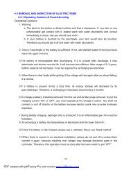
FOREWORD<br />
This manual introduces <strong>650</strong>NK (CF<strong>650</strong> model)<br />
maintenance information, disassembly procedure,<br />
check & adjustment methods, troubleshooting and<br />
technical specifications. There are illustrations,<br />
drawings to guide your operation.<br />
CFMOTO has final explanations to this manual<br />
information. Without our prior written approval, the<br />
manual cannot be dupliacted and disclosed to third<br />
party.<br />
CFMOTO reserves rights to make improvements<br />
and modifications to the products without prior<br />
notice. Overhaul and maintenance should be done<br />
according to actual condition of vehicle.<br />
This manual is compiled according to standard<br />
GB9969.1-1998 and GB/T19678-2005.<br />
INDEX<br />
General Information 1<br />
Periodic Maintenance 2<br />
Fuel System (EFI) 3<br />
Cooling System 4<br />
Engine Top End 5<br />
Clutch 6<br />
Engine Lubrication System 7<br />
Engine Removal/Installation 8<br />
Crankshaft/Transmission 9<br />
Wheels/Tires 10<br />
Final Drive 11<br />
Brakes 12<br />
Suspension 13<br />
Steering 14<br />
Frame 15<br />
Electrical System 16<br />
Click on index line to go.
Abbreviations Table<br />
A ampere ib pound(s)<br />
ABDC after bottom dead center m meter(s)<br />
AC alternating current min minute(s)<br />
ATDC after top dead center N newton(s)<br />
BBDC before bottom dead center Pa pascal(s)<br />
BDC bottom dead center PS horsepower<br />
BTDC before top dead center psi pound(s) per square inch<br />
o<br />
C degree(s) Celsius r revolution<br />
DC direct current rpm revolution(s) per minute<br />
F farad(s) TDC top dead center<br />
o<br />
F degree(s) Fahrenheit TIR total indicator reading<br />
ft foot, feet V volt(s)<br />
g gram(s) W watt(s)<br />
h hour(s) Ω ohm(s)<br />
l<br />
liter(s)
INTRODUCTION<br />
This manual is designed primarily for use by<br />
well-trained mechanics in a properly equipped<br />
workshop. So the operator should have basic and<br />
necessary mechanical and electrical knowledge,<br />
as well as knowledge of proper use of tools. If<br />
you don’t have enough experience, it is better to<br />
ask qualifi ed operator to work. In order to perform<br />
the work efficiently and to avoid costly mistakes,<br />
it is important to read the manual thoroughly. For<br />
the warranty period, it is recommended to repair<br />
and maintain completely following this service<br />
manual. Any maintenance or repair procedure not<br />
performed in accordance with this manual may<br />
void warranty.<br />
To get the longest life out of your vehicle.<br />
● Perform periodic maintenance by following this<br />
manual. Be alert for problems and non-scheduled<br />
maintenance.<br />
● Use genuine CFMOTO parts and proper tools.<br />
There are necessary information about genuine<br />
parts and special tools in our parts catalogue and<br />
special tools list. Follow the service manual<br />
procedures step by step. Do not take shortcuts.<br />
● Remember to keep complete records of maintenance<br />
and repair with dates and any new parts<br />
installed.<br />
How to Use This <strong>Manual</strong><br />
Whenever you see these WARING or CAUTION<br />
symbols, heed the instructions. Always follow safe<br />
operating and maintenance practices.<br />
! WARNING<br />
This warning symbol identifi es special instructions<br />
or procedures which, if not correctly followed,<br />
could result in personal injury or loss of life.<br />
CAUTION<br />
This caution symbol identifies special<br />
instructions or procedures which, if not<br />
strictly observed, could result in damage to or<br />
destruction of equipment.<br />
This manual contains four more symbols (in<br />
addition to WARNING and CAUTON) which will<br />
help you distinguish different types of information.<br />
NOTE<br />
○ This note symbol indicates points of particular interest<br />
for more efficient and convenient operation.<br />
● Indicates a procedural step or work to be done.<br />
○ Indicates a procedural sub-step or how to do the<br />
work. It also precedes the text of NOTE.<br />
Indicates a conditional step or what action to<br />
take based on the results of text or inspection.
GENERAL INFORMATION 1-7<br />
General Information<br />
Table of Contents<br />
Safety Precautions.................................................................................................................... 1-2<br />
Before Servicing.................................................................................................................. 1-4<br />
Model Identification............................................................................................................. 1-9<br />
General Specifications........................................................................................................ 1-10<br />
Unit Convertion Table.......................................................................................................... 1-13
1-2 GENERAL INFORMATION<br />
Safety Precautions<br />
Exhaust contains toxic ingredients. Do not run the<br />
engine in enclosed or poorly-ventilated areas.<br />
When the engine just stops, the temperature<br />
of engine, muf fler is still high; please do not<br />
touch them with bare hands, for avoiding burn.<br />
Please wear uniform with long sleeves as well<br />
as gloves when maintaining.<br />
The liquor (dilute sulfuric acid) in Battery is strongly<br />
corrosive; it may burn the skin and blind the eyes<br />
when it contacts them. In case of contact, please<br />
wash it with a great deal of clear water immediately,<br />
and seek medical treatment in hospital. Besides,<br />
please also wash it by a great deal of clear water<br />
when it contacts the clothes, for avoiding skin burn.<br />
The Battery and Battery liquor must be stored<br />
strictly out of reach of children.<br />
The coolant is poisonous, please do not drink it,<br />
do not let it contact the skin, eyes neither clothes.<br />
In case it contacts the skin or clothes, please<br />
rinse it immediately. When it contacts the eyes,<br />
please wash it thoroughly with a great deal of clear<br />
water immediately, and seek medical treatment in<br />
hospital. In case the coolant is drunk by mistake,<br />
please try to throw it up, and seek medical<br />
treatment immediately after gargling. The coolant<br />
must be stored strictly out of reach of children.<br />
Uniform (pilot uniform etc), cap, safety boots<br />
suitable for the operation must be worn, and the<br />
safety articles such as dustproof goggles, dustproof<br />
respirator and gloves shall be worn for protection<br />
when necessary.<br />
No smoking or naked fire is allowed at the<br />
operation site, for the gasoline is combustible. Not<br />
only f ames, but electric sparks shall be avoided.<br />
Besides, the vapored gasoline is explosive, please<br />
operate it in the place with nice ventilation.
GENERAL INFORMATION 1-3<br />
Safety Precautions<br />
The Battery may produce combustible and<br />
explosive hydrogen when it is being charged. So it<br />
may explode if there is f ame or electric spark. So<br />
please charge it in the place with nice ventilation.<br />
The personnel shall make them be aware of each<br />
other from time to time when operating, for safety<br />
conf rmation.<br />
Do not touch the turning or movable pieces such<br />
as rear wheel, clutch, etc. Pay attention not to get<br />
pinched when servicing.
GENERAL INFORMATION 1-3<br />
Before Servicing<br />
Before starting to perform an inspection service or carry out disassembly and installation on a motorcycle,<br />
read the precautions given below. To facilitate acutal operations, notes, illustrations, photograghs, cautions<br />
and descriptions have been included in each chapter wherever necessary.This section explains the items that<br />
require particular attentions during removal and reassembly.<br />
Special Notes for the Following:<br />
Battery Ground<br />
Before completing any service on the motorcycle,<br />
disconnect the battery cables from the battery to<br />
prevent the engine from accidentally turning over.<br />
Disconnect the ground cable (-) first and then the<br />
positive (+).When finishing the service, first connect<br />
positive(+) cable to the positive (+) terminal of the<br />
battery and then the negative (-) cable to the<br />
negative (-) terminal.<br />
Disassembly<br />
Assembly<br />
Edges of Parts<br />
When service parts with edges, wearing<br />
gloves to prevent injury.<br />
Solvent<br />
Use a high-flush point solvent when cleaning parts.<br />
High-flush point solvent should be used according to<br />
directions of solvent manufacturer.<br />
Cleaning Vehicle Before Disassembly<br />
Clean the vehicle completely before disassembly.Dirt<br />
or other foreign materials entering into sealed areas<br />
during vehicle disassembly can cause excessive wear<br />
and reduce vehicle performance.
GENERAL INFORMATION 1-5<br />
Arrangement and Cleaning of Removed Parts<br />
Disassembled parts are easy to confuse.Arrange the<br />
parts according to the order of parts disassembled<br />
and clean the parts in order prior to installation.<br />
Storage of Removed Parts<br />
After all the parts including subassembly parts have<br />
been cleaned, store the parts in a clean area, put a<br />
clean cloth or plastic sheet over the parts to protect<br />
from any foreign materials that may collect before reassembly.<br />
Inspection<br />
Reuse of worn or damaged parts may lead to serious<br />
accidents.Visually inspect removed parts for corrosion,<br />
discoloration or other damage.Refer to the appropriate<br />
sections of this manual for service limits on individual<br />
parts. Replace the parts if any damage has been<br />
found or if the part beyond the service limits.<br />
Replacement Parts<br />
Replacement parts must be CFMOTO genuine or recommended<br />
by CFMOTO. Gaskets, O-rings, oil seals,<br />
grease seals, circlips or cotter pins must be replaced<br />
with new ones whenever disassembled<br />
Assembly Order<br />
In most cases assembly order is the reverse of<br />
disassembly.However,if assembly order is provided in<br />
the <strong>Service</strong> <strong>Manual</strong>, follow the procedures given.
1-6 GENERAL INFORMATION<br />
Tightening Sequence<br />
Generally, when installing a part with several bolts,<br />
nuts or screws, start them all in their holes and tighten<br />
them in snug fit. Then tighten them according to specified<br />
sequence to prevent case warpage or deformation<br />
which can lead to malfunction.Conversely when<br />
loosening the bolts, nuts or screws, first loosen all of<br />
them by a quarter turn and then remove them. If the<br />
specified sequences is not indicated, tighten the fasteners<br />
alternating diagnoally.<br />
Tightening Torque<br />
Incorrect torque applied to a bolt, nut or screw may<br />
lead to serious damage. Tighten fasteners to the specified<br />
torque by using a good quality torque wrench.<br />
Often, the tightening sequence is followed twice initial<br />
tightening and final tightening torque.<br />
Porper Force<br />
Use common sense during disassembly and<br />
assembly.excessive force can cause expensive or hard<br />
to repair damage.When necessary, remove screws<br />
that have non-permanent locking agent applied using<br />
an impact driver. Use a plastic-faced mallet whenever<br />
tapping is necessary.<br />
Gasket and O-ring<br />
Hardening, shrinkage, or damage of both gaskets and<br />
O-ring after disassembly can reduce sealing<br />
performance.<br />
Liquid Gasket,Non-permanent Locking Agent<br />
For applications that require Liquid Gasket or a nonpermanent<br />
locking agent, clean the surfaces so that<br />
no oil residue remains before applying liquid gasket or<br />
non-permanent locking agent. Do not apply them<br />
excessively, excessive application can clog oil passages<br />
and causes serious damage.
GENERAL INFORMATION 1-7<br />
Press<br />
For items such as bearing or oil seals that must be<br />
pressed into place, apply small amount of oil on contact<br />
area. Be sure to maintain proper alignment and<br />
use smooth movements when installing.<br />
Ball Bearing and Needle Bearing<br />
Do not remove ball or needle unless removal is<br />
absolutely necessary. Replace with new ones<br />
whenever removed. Press bearings with manufacturer<br />
and size marks facing out. Press bearing into<br />
place by putting pressure on the correct bearing<br />
race as shown.<br />
Oil seal & Grease Seal<br />
Do not remove pressed oil or grease seals unless removal<br />
is absolutely necessary. Replace with new ones<br />
whenever removed. Press new oil seals with manufacturer<br />
and size marks facing out.Make sure the seal<br />
is aligned properly when installing.<br />
Apply specified grease to the lip of the seal before<br />
Grease<br />
installing the seal.<br />
Circlips, Cotter Pins<br />
Replace circlips or cotter pins that were removed with<br />
new ones. Take care not to open the clip excessively<br />
when installing to prevent deformation.
1-8 GENERAL INFORMATION<br />
Lubrication<br />
It is important to lubricate rotating or sliding parts during<br />
assembly to minimize wear during initial operation.<br />
Lubrication points are called out throughout this<br />
manual.Apply specific oil or grease as specified.<br />
Direction of Engine Rotation<br />
When rotating crankshaft by hand, the free play of<br />
amount of rotating direction will affect adjustment.<br />
Rotate the crankshaft to positive direction (Clockwise<br />
viewed from output side)<br />
Electrical Wires<br />
When connecting electrical wires, first to check color<br />
of wires and unless special instruction, same color of<br />
wires should be connected.<br />
Instrument<br />
Use a meter that has enough accuracy for an accurate<br />
measurement. Read the manufacturer’s instructions<br />
completely before using the meter.Incorrect values<br />
may lead to improper adjustments.
GENERAL INFORMATION 1-9<br />
Marking Locations<br />
Model:<br />
CF<strong>650</strong><br />
VIN No.:<br />
LCEPEVL1-<br />
Engine serial No.: 283MT-<br />
a VIN No.:<br />
b Name Plate:<br />
c Engine Serial N0.:
1-10 GENERAL INFORMATION<br />
General Specifications<br />
Items<br />
CF<strong>650</strong> (<strong>650</strong>NK)<br />
Dimensions:<br />
Overall length<br />
2120mm (83.5in.)<br />
Overall width<br />
780mm (30.7in.)<br />
Overall height<br />
1100mm (43.3in.)<br />
Wheelbase<br />
1415mm (55.7in.)<br />
Road clearance<br />
150mm (5.9in.)<br />
Seat height<br />
895mm (35.2in.)<br />
Dry mass<br />
206kg (454.3lb)<br />
Curb mass<br />
281kg (619.7lb)<br />
Front:<br />
129kg (284.5lb)<br />
Rear:<br />
152kg (335.2lb)<br />
Fuel tank capacity<br />
17L (4.5USgal.)<br />
Performance<br />
Minimum turning radius (LH or RH) 5.4m (17.8ft)<br />
Engine<br />
Type<br />
2-cylinder in line, 4-strokes, DOHC, 8 valves and liquidcooled<br />
Cooling system<br />
liquid-cooled<br />
Bore and stroke<br />
83 × 60 mm (3.3 × 2.4 in.)<br />
Displacement<br />
649.3 cm³ (39.60 cu in.)<br />
Compression ratio 11.3 : 1<br />
Max. power<br />
52 kW (70.6 PS) @8 500 r/min (rpm)<br />
Max. torque<br />
62 N•m (6.3 kgf•m, 46 ft•lb) @7 000 r/min (rpm)<br />
Carburetion system<br />
Fuel injection system<br />
Starting system<br />
Electric starter<br />
Ignition system<br />
ECU<br />
Timing advance<br />
Controlled by ECU<br />
Ignition timing<br />
From 10° BTDC @1 300 r/min (rpm)to 33° BTDC @6000r/<br />
min (rpm)<br />
Spark plug<br />
CR8EI<br />
Cylinder numbering methods left to right 1-2<br />
Firing order 1-2<br />
Valve timing<br />
Intake:<br />
Open<br />
31° BTDC<br />
Close<br />
61° ABDC<br />
Duration 272°
GENERAL INFORMATION 1-11<br />
Items<br />
CF<strong>650</strong> (<strong>650</strong>NK)<br />
Exhaust:<br />
Open<br />
50°BBDC<br />
Close<br />
30°ATDC<br />
Duration 260°<br />
Lubrication system<br />
Forced lubrication(semi-dry sump)<br />
Engine oil:<br />
Type<br />
API SG or API SH,SJ or SL with JASOMA<br />
Viscosity SAE 15W-40<br />
Oil capacity<br />
Without replacement of oil fi lter:2.0L<br />
If replacement of oil fi lter:2.2L<br />
If drain oil completely:2.6L<br />
Drive train<br />
Primary reduction system:<br />
Type<br />
Gear<br />
Reduction ratio 2.095(88/42)<br />
Clutch type<br />
Wet, multi disc<br />
Transmission:<br />
Type<br />
6-speed,constant mesh, return shift<br />
Gear ratios:<br />
1st<br />
2.353 (39/16)<br />
2nd<br />
1.714 (36/21)<br />
3rd<br />
1.333 (32/24)<br />
4th<br />
1.111 (30/27)<br />
5th<br />
0.966 (28/29)<br />
6th<br />
0.852 (23/27)<br />
Final drive system<br />
Type<br />
Chain drive<br />
Reduction ratio 3.067(46/15)<br />
Overall drive ratio<br />
5.474(@ Top gear)<br />
Frame<br />
Type<br />
Tubular, diamond<br />
Caster angle(Rake angle) 24.5°<br />
Trail<br />
102mm (4.0in.)<br />
Front tire<br />
Type<br />
Tubeless<br />
Size<br />
120/70R17 (58H)<br />
Rim size 17×3.50<br />
Rear tire<br />
Type<br />
Tubeless<br />
Size<br />
160/60R17 (69H)<br />
Rim size 17×4.50<br />
Front suspension<br />
Type<br />
Telescopic fork<br />
Wheel travel<br />
120mm (4.7in.)
1-12 GENERAL INFORMATION<br />
Items<br />
Rear suspension<br />
Type<br />
Wheel travel<br />
Brake type<br />
Front<br />
Rear<br />
Electrical system<br />
Battery<br />
Headlight<br />
Type<br />
Bulb<br />
Tail/Brake light<br />
Alternator<br />
Type<br />
Rated output<br />
CF<strong>650</strong> (<strong>650</strong>NK)<br />
Swingarm<br />
125mm(4.9 in.)<br />
Double disc<br />
Single disc<br />
12V 10Ah<br />
Semi-sealed beam<br />
Hi: H7 12V55W Low: H7 12V55W<br />
LED 12V 0.39W/1.55W<br />
Three-phase AC<br />
25A/14V @5000 rpm
GENERAL INFORMATION 1-13<br />
Prefixes for units<br />
Units of Length<br />
Prefi x Symbol Power Km × 0.6214 = mile<br />
Mega M ×1000000 m × 3.281 = ft<br />
Kilo k ×1000 mm × 0.03937 = in<br />
Centi c ×0.01 Units of Torque<br />
Milli m ×0.001 N·m × 0.1020 = Kgf·m<br />
Micro μ ×0.000001 N·m × 0.7376 = Ft·lb<br />
Units of Mass<br />
N·m × 8.851 = In·lb<br />
Kgf·m × 9.807 = N·m<br />
Kg × 2.205 = Lb Kgf·m × 7.233 = Ft·lb<br />
g × 0.03527 = oz Kgf·m × 86.80=In·lb<br />
Units of Volume<br />
Units of Pressure<br />
L × 0.2642 = gal (US) KPa × 0.01020 = Kgf/cm 2<br />
L × 0.2200 = gl (imp) KPa × 0.1450 = psi<br />
L × 1.057 = qt (US) KPa × 0.7501 = cmHg<br />
L × 0.8799 = qt (imp) Kgf/cm 2 × 98.07 = KPa<br />
L × 2.113 = pint (US)<br />
L × 1.816 = pint(imp)<br />
mL × 0.03381 = oz (US)<br />
mL × 0.02816 = oz (imp)<br />
mL×0.06102 = cuin<br />
Units of Force<br />
N × 0.1020 = Kg<br />
N × 0.2248 = Lb<br />
Kg × 9.807 = N<br />
Kgf/cm 2 × 14.22 = psi<br />
cmHg × 1.333 = KPa<br />
Units of Speed<br />
Km/h×0.6214=mph<br />
Units of Power<br />
Kw×1.360=PS<br />
Kw×1.341=HP<br />
PS×0.7355=KW
PERIODIC MAINTENANCE 2-1<br />
Periodic Maintenance<br />
Table of Contents<br />
Periodic Maintenance Chart..................................................................................................... 2-3<br />
Torque Specifications............................................................................................................... 2-6<br />
Specifications and <strong>Service</strong> Limit............................................................................................... 2-11<br />
Special Tools............................................................................................................................. 2-13<br />
Periodic Maintenance procedures............................................................................................ 2-14<br />
Fuel System (EFI)................................................................................................................... 2-14<br />
Air Filter Element Cleaning................................................................................................... 2-14<br />
Throttle Control System Inspection...................................................................................... 2-15<br />
Idle Speed Inspection........................................................................................................... 2-16<br />
Fuel Line Inspection (fuel leak, damage, installation condition)............................................ 2-17<br />
Cooling System...................................................................................................................... 2-18<br />
Coolant Level Inspection...................................................................................................... 2-18<br />
Radiator Hose Damage and Installation Condition Inspection.............................................. 2-18<br />
Engine Top End...................................................................................................................... 2-19<br />
Valve Clearance Inspection.................................................................................................. 2-19<br />
Valve Clearance Adjustment................................................................................................ 2-20<br />
Clutch..................................................................................................................................... 2-25<br />
Clutch Operation Inspection................................................................................................. 2-25<br />
Wheels/Tires........................................................................................................................... 2-25<br />
Air Pressure Inspection........................................................................................................ 2-25<br />
Wheel/Tire Damage Inspection............................................................................................ 2-26<br />
Tire Tread Wear, Abnormal Wear Inspection........................................................................ 2-26<br />
Wheel Bearing Damage Inspection...................................................................................... 2-27<br />
Drive Train.............................................................................................................................. 2-27<br />
Drive Chain Lubrication Condition Inspection....................................................................... 2-27<br />
Drive Chain Slack Inspection............................................................................................... 2-28<br />
Drive Chain Slack Adjustment.............................................................................................. 2-28<br />
Wheel Alignment Inspection................................................................................................. 2-29<br />
Drive Chain Wear Inspection................................................................................................ 2-30<br />
Chain Guide Inspection........................................................................................................ 2-30<br />
Brake System......................................................................................................................... 2-31<br />
Brake Fluid Leak (Brake Hose and Pipe) Inspection............................................................ 2-31<br />
Brake Hose and Pipe Damage and Installation Condition Inspection................................... 2-31<br />
Brake Operation Inspection.................................................................................................. 2-32<br />
Brake Fluid Level Inspection................................................................................................ 2-32<br />
Brake Pad Wear Inspection.................................................................................................. 2-33<br />
Brake Light Switch Operation Inspection.............................................................................. 2-33
2-2 PERIODIC MAINTENANCE<br />
Suspensions........................................................................................................................... 2-34<br />
Front Forks/Rear Shock Absorber Operation Inspection...................................................... 2-34<br />
Front Fork Oil Leak Inspection............................................................................................. 2-34<br />
Rear Shock Absorber Oil Leak Inspection............................................................................ 2-34<br />
Steering System..................................................................................................................... 2-35<br />
Steering Play Inspection...................................................................................................... 2-35<br />
Steering Play Adjustment..................................................................................................... 2-35<br />
Steering Stem Bearing Lubrication....................................................................................... 2-36<br />
Electrical System.................................................................................................................... 2-36<br />
Spark Plug Condition Inspection.......................................................................................... 2-36<br />
Lights and Switches Operation Inspection........................................................................... 2-37<br />
Headlight Aiming Inspection................................................................................................. 2-39<br />
Sidestand Switch Operation Inspection................................................................................ 2-40<br />
Engine Stop Switch Operation Inspection............................................................................ 2-41<br />
Others..................................................................................................................................... 2-42<br />
Chassis Parts Lubrication.................................................................................................... 2-42<br />
Bolts, Nuts and Fasteners Tightness Inspection................................................................... 2-43<br />
Replacement Parts................................................................................................................. 2-44<br />
Air Filter Element Replacement............................................................................................ 2-44<br />
Fuel Line Replacement........................................................................................................ 2-44<br />
Coolant Change................................................................................................................... 2-45<br />
Radiator Hose and O-ring Replacement.............................................................................. 2-47<br />
Engine Oil Change............................................................................................................... 2-48<br />
Oil Filter Replacement.......................................................................................................... 2-48<br />
Brake Hose and Pipe Replacement..................................................................................... 2-49<br />
Brake Fluid Change............................................................................................................. 2-49<br />
Master Cylinder Rubber Parts Replacement........................................................................ 2-50<br />
Caliper Rubber Parts Replacement...................................................................................... 2-52<br />
Spark Plug Replacement..................................................................................................... 2-54
PERIODIC MAINTENANCE 2-3<br />
Periodic Maintenance Chart<br />
The scheduled maintenance must be done in accordance with this chart to keep the motorcycle in good<br />
running condition.The initial maintenance is vitally important and must not be neglected.<br />
■:This service must be performed by an authorized CFMOTO dealer.<br />
*:For higher odometer readings,repeat at the frequency interval established here.<br />
#:<strong>Service</strong> more frequently when operating in servere conditions;dusty,wet,muddy,high speed,or frequent<br />
starting/stopping.<br />
1.Periodic Inspection<br />
FREQUENCY<br />
Whichever<br />
Comes<br />
First<br />
<br />
*ODOMETER READINGS<br />
→ km×1000<br />
1 6 12 18 24 30 36<br />
See<br />
Page<br />
Every<br />
INSPECTION<br />
■ Air fi lter element - clean ● ● ● 2-14<br />
■Valve clearance-inspect 42000km 2-19<br />
Throttle control system (play, smooth return, year ● ● ● ● 2-15<br />
no drag) - inspect<br />
Idle speed - inspect ● ● ● ● 2-16<br />
■ Fuel leak (fuel hose and pipe) - inspect year ● ● ● ● 2-17<br />
■ Fuel hose and pipe damage - inspect year ● ● ● ● 2-17<br />
■ Fuel hose and pipe installation condition year ● ● ● ● 2-17<br />
- inspect<br />
■Throttle body—clean ● ● ● ● ● ● —<br />
Coolant level - inspect ● ● ● ● 2-18<br />
Coolant leak (radiator hose and pipe) - year ● ● ● ● 2-18<br />
inspect<br />
Radiator hose damage - inspect year ● ● ● ● 2-18<br />
Radiator hose installation condition - inspect year ● ● ● ● 2-18<br />
■ Air intake system damage - inspect ● ● ●<br />
Clutch and Drive Train<br />
Clutch operation (play, disengagement,<br />
● ● ● ● 2-25<br />
engagement) - inspect<br />
Drive chain lubrication condition - inspect # 600km 2-27<br />
Drive chain slack - inspect # 1000km 2-28<br />
Drive chain wear - inspect # ● ● ● 2-30<br />
■ Drive chain guide wear - inspect ● ● ● 2-30
2-4 PERIODIC MAINTENANCE<br />
FREQUENCY<br />
Whichever<br />
comes<br />
fi rst<br />
↓<br />
*ODOMETER READING<br />
→ km×1000<br />
1 6 12 18 24 30 36<br />
See Page<br />
Every<br />
INSPECTION<br />
Wheels/Tires<br />
Tire air pressure - inspect year ● ● ● ● 2-25<br />
Wheel/tire damage - inspect ● ● ● 2-26<br />
Tire tread wear, abnormal wear - inspect ● ● ● 2-26<br />
■Wheel bearing damage - inspect year ● ● ● 2-27<br />
Footrest—lubricate ● ● ● ● —<br />
Brake System<br />
Brake fl uid leak (brake hose and pipe) - year ● ● ● ● ● ● ● 2-31<br />
inspect<br />
Brake hose and pipe damage - inspect year ● ● ● ● ● ● ● 2-31<br />
Brake pad wear - inspect # ● ● ● ● ● ● 2-33<br />
Brake hose and pipe installation condition year ● ● ● ● ● ● ● 2-31<br />
- inspect<br />
Brake fluid level - inspect 6 months ● ● ● ● ● ● ● 2-32<br />
Brake operation (effectiveness, play, no year ● ● ● ● ● ● ● 2-33<br />
drag) - inspect<br />
Brake light switch operation - inspect ● ● ● ● ● ● ● 2-33<br />
Suspensions<br />
Front forks/rear shock absorber operation<br />
● ● ● 2-34<br />
(damping and smooth stroke) - inspect<br />
Front forks/rear shock absorber oil leak - year ● ● ● 2-34<br />
inspect<br />
Steering System<br />
■Steering play - inspect year ● ● ● ● 2-35<br />
■Steering stem bearings - lubricate year ● 2-36<br />
Electrical System<br />
Lights and switches operation - inspect year ● ● ● 2-37<br />
Headlight aiming - inspect year ● ● ● 2-39<br />
Sidestand switch operation - inspect year ● ● ● —<br />
Engine stop switch operation - inspect year ● ● ● —<br />
Chassis<br />
■Chassis parts - lubricate year ● ● ● —<br />
■Bolts,nuts tightening torque—inspect ● ● ● ● —
PERIODIC MAINTENANCE 2-5<br />
FREQUENCY<br />
Whichever<br />
comes<br />
fi rst<br />
↓<br />
*ODOMETER READING<br />
→km×1000<br />
1 12 24 36 48<br />
See Page<br />
Every<br />
CHANGE/REPLACE ITEM<br />
■Air filter element# 2 years 2-14<br />
Engine oil # 6 months Every 6000 km 2-48<br />
Oil fi lter 6 months Every 6000 km 2-48<br />
■Fuel line 4 years ● —<br />
■Coolant 2 years ● 2-45<br />
■Radiator hose 2 years ● —<br />
■Brake hose and pipe 4 years ● —<br />
■Brake fluid (F/R) 2 years ● ● 2-50<br />
■Rubber parts of master cylinder and 4 years ● —<br />
caliper<br />
■Spark plug ● ● ● ● 2-54
2-6 PERIODIC MAINTENANCE<br />
Torque Specifications<br />
The following tables list the tightening torque for the major fasteners requiring use of a threadlocker.<br />
Letters used in "emarks" column mean:<br />
AL: Tighten the two clamp bolts alternately two times to ensure even tightening torque;<br />
EO: Apply engine oil;<br />
L: Apply a threadlocker to the threads;<br />
Lh: Left-hand threads;<br />
MO: Apply molibdenum disulfi de oil solution(mixture of engine oil and molybdenum disulfi de grease in a<br />
weight ratio 10:1);<br />
R: Replacement Parts;<br />
S: Follow the specified tightening sequence;<br />
Si: Apply silicone grease (ex.PBC grease);<br />
SS: Apply silicone sealant<br />
Fastener<br />
Torque<br />
N·m kgf·m ft·lb<br />
Remarks<br />
Electronic Fuel Injection(EFI)<br />
Coolant Temp. Sensor 12 1.2 106in·lb<br />
Speed Sensor Bolt 8 0.80 69in·lb L<br />
Fuel Pump Bolts 5 0.5 — L,S<br />
Oxygen Sensor 60 6.60 44.3<br />
Cooling System<br />
Radiator Hose Clamp Bolts 2.5 0.25 —<br />
Water Pump Impeller Bolt 10 1.0 87in·lb<br />
Water Pump Cover Bolts 10 1.0 87in·lb<br />
Water Pump Drain Bolt 7.0 0.70 62in·lb<br />
Thermostat Housing Bolts 10 1.0 87in·lb<br />
Coolant Temp. Sensor 12 1.2 106in·lb<br />
Baffl e Plate Bolts 6 0.60 52in·lb See text<br />
Engine Top End<br />
Valve Cover Bolts 10 1.0 87in·lb<br />
Camshaft Cap Bolts 12 1.2 106in·lb S<br />
Cylinder Head Bolts (M10 New Bolts) 54 5.5 40 MO,S<br />
Cylinder Head Bolts (M10 Used Bolts) 49 5.0 36 MO,S<br />
Cylinder Bolt (M8) 27.5 2.8 20 MO,S<br />
Cylinder Nut (M10) 49 5.0 36 MO,S<br />
Cylinder Head Bolts (M6) 12 1.2 106in·lb S<br />
Cylinder Bolts (M6) 12 1.2 106in·lb S<br />
Intake Manifold Bolts 12 1.2 106in·lb<br />
Intake Manifold Clamp 2.0 0.2 1.5<br />
Camshaft Chain Tensioner Bolts 12 1.2 12<br />
Camshaft Chain Tensioner Nuts Mounting Bolts 20 1.2 20<br />
Camshaft Sprocket Bolts 15 1.5 11 L<br />
Spark Plug 15 1.5 11<br />
Exhaust Pipe Manifold Holder Nuts 17 1.7 12<br />
Muffl er Body Mounting Bolt (Front) 20 2.0 15
PERIODIC MAINTENANCE 2-7<br />
Fastener<br />
Torque<br />
N·m kgf·m ft·lb<br />
Remarks<br />
Muffl er Body Mounting Bolt (Rear) 20 2.0 15<br />
Baffl e Plate Bolts 6 0.60 52in·lb See text<br />
Clutch<br />
Oil Filler Plug – – – Finger tighten<br />
Clutch Cover Mounting Bolts 10 1.0 87in·lb<br />
Clutch Spring Bolts 10 1.0 87in·lb<br />
Clutch Hub Nut 132 13.5 98 R<br />
Clutch Lever Clamp Bolts 10 1.0 87in·lb S<br />
Oil Pump Chain Guide Bolts 12 1.2 106in·lb L<br />
Clutch Cable Holder Bolts 10 1.0 87in·lb L<br />
Clutch Cable Clamp Bolt 10 1.0 87in·lb<br />
Engine Lubrication<br />
Drain Bolt 30 3.0 22<br />
Filler Plate Bolts 10 1.0 87in·lb L<br />
Oil Filter 17 1.75 13 EO,R<br />
Holder Mounting Bolt 25 2.5 18 L<br />
Oil Pan Bolts 12 1.2 106in·lb<br />
Oil Pump Chain Guide Bolts 12 1.2 106in·lb L<br />
Oil Pipe Plate Bolt 10 1.0 87in·lb L<br />
Oil Pressure Relief Valve 15 1.5 11 L<br />
Oil Pressure Switch 15 1.5 11 SS<br />
Oil Pump Cover Bolts 10 1.0 87in·lb L<br />
Lower Fairing Bracket Bolts 12 1.2 106in·lb L<br />
Oil Pump Sprocket Bolt 12 1.2 106in·lb L,Lh<br />
Oil Passage Plug 20 2.0 15 L<br />
Engine Removal/Installation<br />
Rear Engine Mounting Nuts 45 4.6 32 S<br />
Engine Mounting Bracket Bolts 25 2.5 18 S<br />
Front Engine Mounting Bolts 45 4.6 32 S<br />
Crankshaft/Transmission<br />
Breather Plate Bolts 10 1.0 87in·lb L<br />
Crankcase Bolts (M9, L = 113 mm) 44 4.5 32 MO,S<br />
Crankcase Bolts (M9, L = 83 mm) 44 4.5 32 MO,S<br />
Crankcase Bolts (M8, L = 73 mm) 35 3.6 26 MO,S<br />
Crankcase Bolts (M8, L = 60 mm) 35 3.6 26 MO,S<br />
Crankcase Bolts (M8, L = 110 mm) 27.5 2.8 20 S<br />
Crankcase Bolts (M8, L = 50 mm) 27.5 2.8 20 S<br />
Crankcase Bolts (M7) 20 2.0 15 S<br />
Upper Crankcase Bolts 27.5 2.8 20 S
2-8 PERIODIC MAINTENANCE<br />
Fastener<br />
Torque<br />
N·m kgf·m ft·lb<br />
Remarks<br />
Shift Drum Bearing Holder Screw 5 0.50 43in·lb L<br />
Connecting Rod Big End Nuts see text ← ← MO<br />
Timing Rotor Bolt 40 4.1 30<br />
Oil Pressure Switch 15 1.5 11 SS<br />
Gear Positioning Lever Bolt 12 1.2 106in·lb L<br />
Shift Shaft Return Spring Pin 29 2.9 22 L<br />
Shift Drum Cam Bolt 12 1.2 106in·lb L<br />
Neutral Switch 15 1.5 11<br />
Transmission Case Bolts 20 2.0 15<br />
Neutral Switch Holder Screw 5 0.50 43in·lb L<br />
Shift Shaft Cover Bolts 10 1.0 87in·lb L(2)<br />
Shift Shaft Cover Screw 5 0.50 43in·lb L<br />
Wheels/Tires<br />
Front Axle 108 11.0 80<br />
Front Axle Clamp Bolt 34 3.5 25<br />
Rear Axle Nut 108 11.0 80<br />
Final Drive<br />
Engine Sprocket Nut 125 12.7 92 MO<br />
Rear Axle Nut 108 11.0 80<br />
Rear Sprocket Nuts 59 6.0 44<br />
Speed Sensor Bolt 8 0.80 69in·lb L<br />
Speed Sensor Bracket Bolts 10 1.0 87in·lb<br />
Brakes<br />
Bleed Valve 7.8 0.80 69in·lb<br />
Brake Hose Banjo Bolts 25 2.5 18<br />
Brake Lever Pivot Bolt 1.0 0.10 9in·lb Si<br />
Brake Lever Pivot Bolt Locknut 5.9 0.60 52in·lb<br />
Brake Pedal Bolt 8.8 0.90 78in·lb<br />
Front Brake Disc Mounting Bolts 27 2.8 20 L<br />
Front Brake Light Switch Screw 1.0 0.10 9in·lb<br />
Front Brake Reservoir Cap Screws 1.0 0.10 9in·lb<br />
Front Caliper Mounting Bolts 34 3.5 25<br />
Front Master Cylinder Clamp Bolts 8.8 0.90 78in·lb S<br />
Rear Brake Disc Mounting Bolts 27 2.8 20 L<br />
Rear Caliper Mounting Bolts 25 2.5 18<br />
Rear Master Cylinder Mounting Bolts 25 2.5 18<br />
Rear Master Cylinder Push Rod Locknut 18 1.8 13<br />
Suspension<br />
Front Axle Clamp Bolt 34 3.5 25<br />
Front Fork Bottom Allen Bolts 30 3.1 22 L
PERIODIC MAINTENANCE 2-9<br />
Fastener<br />
Torque<br />
N·m kgf·m ft·lb<br />
Remarks<br />
Front Fork Clamp Bolts (Lower) 20 2.0 15 AL<br />
Front Fork Clamp Bolts (Upper) 20 2.0 15<br />
Front Fork Top Plugs 25 2.5 18<br />
Rear Shock Absorber Bolt 59 6.0 44<br />
Rear Shock Absorber Nut 59 6.0 44<br />
Swingarm Pivot Shaft Nut 180 — —<br />
Steering<br />
Front Fork Clamp Bolts (Lower) 20 2.0 15 AL<br />
Front Fork Clamp Bolts (Upper) 20 2.0 15<br />
Handlebar Holder Bolts 25 2.5 18 S<br />
Left Switch Housing Screws 3.5 0.36 31 in·lb<br />
Right Switch Housing Screws 3.5 0.36 31 in·lb<br />
Steering Stem Head Bolt 108 11.0 80<br />
Steering Stem Nut 20 2.0 15<br />
Frame<br />
Footrest Stay Bolts 34 3.5 25<br />
Front Fender Bolts 3.9 0.40 35 in·lb<br />
Front Fender Bracket Bolts 8.8 0.90 78 in·lb L<br />
Front Turn Signal Light Mounting Screws 1.2 0.12 11 in·lb<br />
Grab Rail Mounting Bolts 25 2.5 18<br />
Lower Fairing Mounting Bolts 8.8 0.90 78 in·lb<br />
Seat Lock Mounting Screws 1.2 0.12 11 in·lb<br />
Sidestand Bolt 44 4.5 32<br />
Sidestand Switch Bolt 8.8 0.90 78 in·lb L<br />
Electrical System<br />
Alternator Cover Bolts 10 1.0 87 in·lb<br />
Alternator Lead Holding Plate Bolt 10 1.0 87 in·lb L<br />
Alternator Rotor Bolt 155 15.8 114 MO<br />
Crankshaft Position Sensor Bolts 6.0 0.60 53 in·lb<br />
Engine Ground Cable Terminal Bolt 9.8 1.0 87 in·lb<br />
Front Brake Light Switch Screw 1.2 0.12 11 in·lb<br />
Front Turn Signal Light Mounting Screws 1.2 0.12 11 in·lb<br />
Left Switch Housing Screws License 3.5 0.36 31 in·lb<br />
Plate Light Cover Screws License 0.90 0.090 8 in·lb<br />
Plate Light Mounting Screws Meter 1.2 0.12 11 in·lb<br />
Neutral Switch 15 1.5 11<br />
Oil Pressure Switch 15 1.5 11 SS<br />
Oxygen Sensor 60 6.10 44.3<br />
Regulator/Rectifi er Bolts 8.8 0.90 78 in·lb<br />
Right Switch Housing Screws 3.5 0.36 31 in·lb<br />
Sidestand Switch Bolt 8.8 0.90 78 in·lb L<br />
Spark Plugs 15 1.5 11
2-10 PERIODIC MAINTENANCE<br />
Fastener<br />
Torque<br />
N·m kgf·m ft·lb<br />
Remarks<br />
Speed Sensor Bolt 8.0 0.80 69in·lb L<br />
Starter Motor Cable Terminal Nut 6.0 0.60 53in·lb<br />
Starter Motor Mounting Bolts 10 1.0 87in·lb L<br />
Stator Coil Bolts 12 1.2 106in·lb L<br />
Timing Rotor Bolt 40 4.1 30<br />
Coolant Temp. Sensor 12.0 1.2 106in·lb<br />
The table below, relating tightening torque to thread diameter, lists the basic torque for the bolts and nuts.<br />
Use this table for only the bolts and nuts which do not require a specifi c torque value. All of the values are<br />
for use with dry solvent-cleaned threads.<br />
Basic Torque for General Fasteners<br />
Threads Diameter<br />
(mm)<br />
Torque<br />
N·m kgf·m ft·lb<br />
5 3.4-4.9 0.35-0.50 30-43in·lb<br />
6 5.9-7.8 0.60-0.80 52-69in·lb<br />
8 14-19 1.4-1.9 10.0-13.5<br />
10 25-34 2.6-3.5 19.0-25<br />
12 44-61 4.5-6.2 33-45<br />
14 73-98 7.4-10.0 54-72<br />
16 115-155 11.5-16.0 83-115<br />
18 165-225 17.0-23.0 125-165<br />
20 225-325 23.0-33.0 165-240
PERIODIC MAINTENANCE 2-11<br />
Specifications and <strong>Service</strong> Limit<br />
EFI<br />
Throttle Grip Free Play<br />
Idle Speed<br />
Air Filter Element<br />
Item Standard <strong>Service</strong> Limit<br />
2~3mm(0.08~0.12in.)<br />
1300±130r/min(rpm)<br />
Polyurethane Foam<br />
Cooling System<br />
Coolant:<br />
Type(recommended)<br />
Color<br />
Mixed Ratio<br />
Freezing Point<br />
Total Amount<br />
Permanent type of antifreeze<br />
Green<br />
Soft water 50%, Coolant 50%<br />
–35°C(–31°F)<br />
1.6L(1.7USqt)<br />
Engine Top End<br />
Valve Clearance<br />
Exhaust<br />
Intake<br />
0.20~0.26mm(0.0078~0.0102in.)<br />
0.08~0.13mm(0.0031~0.0051in.)<br />
– – –<br />
– – –<br />
Clutch<br />
Clutch Lever Free Play 2 ~3mm(0.08~0.12in.) – – –<br />
Engine Lubrication System<br />
Engine Oil:<br />
Type<br />
Viscosity<br />
Capacity<br />
Level<br />
API SG or higher<br />
SAE 15W-40<br />
2.0L(1.8USqt)( when fi lter is not replaced)<br />
2.2L(2.0USqt)( when fi lter is replaced)<br />
2.6L(2.5USqt)( when engine is completely dry)<br />
Between upper and lower level lines<br />
(after idling or running)<br />
– – –<br />
– – –<br />
– – –<br />
– – –<br />
– – –<br />
– – –<br />
Wheels/Tirs<br />
Tread Depth:<br />
Front<br />
Rear<br />
4.5mm(0.18in.)<br />
5.5mm(0.22in.)<br />
0.8~1.0mm<br />
0.8~1.0mm<br />
Air Pressure (when Cold):<br />
Front<br />
Rear<br />
280kPa(2.80kgf/cm 2 ,39.8psi)<br />
280kPa(2.80kgf/cm 2 ,39.8psi)<br />
– – –<br />
– – –
2-12 PERIODIC MAINTENANCE<br />
Item Standard <strong>Service</strong> Limit<br />
Final Drive<br />
Drive Chain Slack<br />
Drive Chain Wear (20-link<br />
Length)<br />
Standard Chain:<br />
Make<br />
Type<br />
Link<br />
30~40mm(1.2~1.6in.)<br />
317.5~318.2mm(12.50 12.53in.)<br />
Japan RK<br />
520×S01<br />
114 links<br />
– – –<br />
323mm(12.7in.)<br />
– – –<br />
– – –<br />
– – –<br />
Brakes<br />
Brake Fluid:<br />
Grade<br />
Brake Pad Lining<br />
Thickness:<br />
Front<br />
Rear<br />
Brake Light Timing:<br />
Front<br />
Rear<br />
DOT4 or DOT5<br />
4mm(0.15in.)<br />
5mm(0.196in.)<br />
Pulled ON<br />
ON after about 10 mm (0.39 in.)<br />
of pedal travel<br />
– – –<br />
1mm(0.04in.)<br />
1mm(0.04in.)<br />
– – –<br />
Electrical System<br />
Spark Plug Gap 0.7~0.9mm(0.027~0.035in.) – – –
PERIODIC MAINTENANCE 2-13<br />
Special Tools<br />
Inside Circlip Pliers<br />
Extension Tube<br />
Steering Stem Nut Wrench Pilot Screw Adjuster,E<br />
Oil Filter Wrench
2-14 PERIODIC MAINTENANCE<br />
Electronic Fuel Injection<br />
Air Filter Element Cleaning<br />
NOTE<br />
O In dusty areas,the element should be cleaned<br />
frequently than the recommended interval.<br />
O After rding through rain or on muddily road,element<br />
should be cleaned immediately.<br />
Screw<br />
! WARNING<br />
If dirt or dust is allowed to pass through<br />
into the throttle assy, the throttle may<br />
become stuck, possibly causing accident.<br />
CAUTION<br />
If dirt gets through into the<br />
engine,excessive engine wear and<br />
possibly engine damage will occur.<br />
Element Comp.<br />
• Remove:<br />
Fuel tank(see Fuel Tank Removal in the Fuel<br />
System);<br />
• Remove air filter element screw;<br />
• Remove air filter element comp..<br />
Element<br />
• Remove the holder.<br />
• Remove element<br />
NOTE<br />
O The wire screen is fastened with an adhesive for<br />
the shaded portion.Do not remove the wire screen.
PERIODIC MAINTENANCE 2-15<br />
! WARNING<br />
Clean the element in a well-ventilated area,<br />
and make sure that there are no sparks or<br />
flame anywhere near the working area.<br />
Because of the danger of highly flammable<br />
liquids,do not use gasoline or a low-flash<br />
point solvent to clean the element.<br />
• Clean the element element [A] in a bath of highflash<br />
point solvent, and then dry it with compressed<br />
air or by shaking it.<br />
• After cleaning, saturate a clean, lint-free towel with<br />
SE, SF, or SG class SAE 30 oil and apply the oil<br />
to the element by tapping the element outside<br />
with the towel.<br />
• Visually check the element for tears or breaks.<br />
• If the element has any tears or breaks, replace<br />
the element.<br />
• lnstall the element unit [A] with the foam element<br />
outside (gray) facing down.<br />
Throttle Control System Inspection<br />
• Check that the throttle grip moves smoothly from<br />
full open to close [A], and the throttle closes<br />
quickly and completely by the return spring in all<br />
steering positions.<br />
If the throttle grip doesn’t return properly, check<br />
the throttle cable routing, grip free play, and cable<br />
damage. Then lubricate the throttle cable.<br />
• Check the throttle grip free play [A].<br />
If the free play is incorrect, adjust the throttle<br />
cable.<br />
Throttle Grip Free Play<br />
Standard: 2~3 mm(0.08~0.12in.)
2-16 PERIODIC MAINTENANCE<br />
If necessary,adjust the throttle cable as follows.<br />
• Loosen the locknut [A] at the upper end of the<br />
accelerate cable.<br />
• Turn the adjuster [B] in completely so as to give<br />
the throttle grip plenty of play.<br />
• Loosen the locknut [A] at the middle of the<br />
decelerate cable.<br />
• Turn the adjuster [B] until there is no play when<br />
the throttle grip is completely closed.<br />
• Tighten the locknut.<br />
• Turn the accelerate cable adjuster until the proper<br />
amount of throttle grip free play is obtained.<br />
• Tighten the locknut.<br />
Idle Speed Inspection<br />
• Start the engine and warm it up thoroughly.<br />
With the engine idling, turn the handlebar to both<br />
sides [A].<br />
If handlebar movement changes the idle speed,<br />
the throttle cables may be improperly adjusted or<br />
incorrectly routed or damaged. Be sure to correct<br />
any of these conditions before diding.<br />
! WARNING<br />
Operation with improperly adjusted,incorrectly<br />
routed or damaged cables could result in<br />
an unsafe riding condition.<br />
• Check the idle speed.<br />
If the idle speed is out of the specified range,<br />
check throttle body for air leaks and calibration.<br />
Idle Speed<br />
Standard: 1300 130 r/min(rpm)
PERIODIC MAINTENANCE 2-17<br />
Fuel Line Inspection (fuel leak, damage,<br />
installation condition)<br />
O The fuel line is designed to be used throughout<br />
the motorcycle’s life without any maintenance.<br />
However, if the motorcycle is not properly<br />
handled, the high pressure inside the fuel line can<br />
cause fuel to leak [A] or the line to burst. Remove<br />
the fuel tank (see Fuel Tank Removal in the<br />
Fuel System chapter) and check the fuel line.<br />
Replace the fuel line if any fraying, cracks [B] or<br />
bulges [C] are noticed.<br />
• Check the line if it has been sharply bent or<br />
kinked.<br />
Hose Joints [A]<br />
Fuel Line [B]<br />
• Check that the hose joints are securely connected.<br />
O Push and pull [A] the hose joint [B] back and forth<br />
more than two times, and make sure it is locked.<br />
If it is not locked,reinstall the hose joint.<br />
!<br />
WARNING<br />
Make sure the hose joint is installed correctly<br />
on the delivery pipe by sliding the joint, or<br />
the fuel could leak.
2-18 PERIODIC MAINTENANCE<br />
Cooling System<br />
Coolant Level Inspection<br />
NOTE<br />
O Check the level when the engine is cold (room or<br />
ambient temperature).<br />
• Check the coolant level in the reserve tank [A]<br />
with the motorcycle held perpendicular (Do not<br />
use the sidestand).<br />
If the coolant level is lower than the “L” level line<br />
[B], remove the right center fairing (see Center<br />
Fairing Removal in the Frame chapter) and unscrew<br />
the reserve tank cap, and add coolant to<br />
the “F” level line [C].<br />
“L”: low<br />
“F”: full<br />
CAUTION<br />
For refilling,add the specified mixture of<br />
coolant and soft water.Adding water alone<br />
dilutes the coolant and degrades its anticorrosion<br />
properties.The diluted coolant can attack<br />
the aluminum engine parts.In an emergency,<br />
soft water alone can be added.But the diluted<br />
coolant must be returned to the correct mixture<br />
ratio within a few days.If coolant must be<br />
added often or the reservoir tank has run<br />
completely dry,there is a probably leakage in<br />
the cooling system.Check the system for leaks.<br />
Coolant ruins paited surfaces.Immediately<br />
wash away any coolant that spills on the<br />
frame,engine,wheels or other painted parts.<br />
Radiator Hose Damage and installation condition<br />
inspection<br />
O The high pressure inside the radiator hose and<br />
pipe can cause coolant to leak [A] or the hose to<br />
burst if the line is not properly maintained.<br />
• Visually inspect the hoses for signs of<br />
deterioration. Squeeze the hoses.A hose should<br />
not be hard and brittle,nor should it be soft or<br />
swollen.<br />
Replace the hose if any fraying, cracks [B] or<br />
bulges [C] are noticed.<br />
• Check that the hoses are securely connected and<br />
clamps are tightened correctly.<br />
Torque-Radiator Hose Clamp Screws:<br />
2.5 N m(0.25 kgf m)
PERIODIC MAINTENANCE 2-19<br />
Engine Top End<br />
Valve Clearance Inspection<br />
NOTE<br />
O Valve clearance must be checked and adjusted<br />
when the engine is cold (room temperature).<br />
• Remove the cylinder head cover (see Cylinder<br />
Head Cover Removal in the Engine Top End chapter)<br />
• Unscrew the upper [A] and lower [B] caps on the<br />
clutch cover.<br />
• Check the valve clearance when the pistons are at<br />
TDC.<br />
O The pistons are numbered beginning with the engine<br />
left side.<br />
• Using a wrench [A] on the crankshaft rotation bolt,<br />
turn the crankshaft clockwise until the “1/T” mark<br />
on the timing rotor is aligned with the notch [B] in<br />
the edge of the upper hole in the clutch cover for #1<br />
piston and “2/T” mark for #2 piston.<br />
1/T Mark [A]<br />
2/T Mark [B]<br />
Hole [C] of Upper Cap<br />
Notch [D] in Edge of Upper Hole<br />
• Using the feeler gauge [A], measure the valve<br />
clearance between cam and valve lifter.<br />
Valve Clearance<br />
Standard:<br />
Exhaust: 0.22~0.31 mm (0.0087~0.0122 in.)<br />
Intake: 0.15~0.21 mm (0.0059~0.0083 in.)
2-20 PERIODIC MAINTENANCE<br />
Valve Clearance Measuring Position #1 Piston<br />
TDC at End of Compression Stroke Intake<br />
valve clearances of #1 piston,and Exhaust valve<br />
clearances of #1 piston<br />
NOTE<br />
O Check the valve clearance using this method only.<br />
Checking the clearance at any other cam position<br />
may result in improper valve clearance.<br />
Valve Clearance Measuring Position #2 Piston<br />
TDC at End of Compression Stroke Intake valve<br />
clearances of #2 piston,and Exhaust valve<br />
clearances of #2 piston<br />
If the valve clearance is not within the specified<br />
range,first record the clearance,and adjust it.<br />
Valve Clearance Adjustment<br />
• To change the valve clearance,remove the cam<br />
shaft chain tensioner,camshafts and valve lifters.<br />
Replace the shim with one of a different thickness.<br />
NOTE<br />
O Mark and record the valve lifter and shim location<br />
so they can be reinstalled in their original positions.<br />
O If there is no clearance,select a shim which is several<br />
sizes smaller and then measure the clearance.<br />
• To select a new shim which brings the valve<br />
clearance within the specified range, refer to the<br />
Valve Clearance Adjustment Charts.<br />
• Apply a thin coat of molybdenum disulfide grease<br />
to the valve lifters.<br />
• Install the camshafts. Be sure to time the cam<br />
shafts properly (see Camshaft Installation in the<br />
Engine Top End chapter).<br />
• Remeasure any valve clearance that wasadjusted.<br />
Readjust if necessary.
PERIODIC MAINTENANCE 2-21<br />
Valve Adjustment Chart(Intake Valve)<br />
Present Shim<br />
Example<br />
Mark 320 322 324 326 328 330 332 334 336 338 340 342 344 346 348 350 352 354 356 358 360 362 364 366<br />
Thickness 3.2 3.22 3.24 3.26 3.28 3.3 3.32 3.34 3.36 3.38 3.4 3.42 3.44 3.46 3.48 3.5 3.52 3.54 3.56 3.58 3.6 3.62 3.64 3.66<br />
0 ~ 0.01 — — — — — 3.2 3.22 3.24 3.26 3.28 3.3 3.32 3.34 3.36 3.38 3.4 3.42 3.44 3.46 3.48 3.5 3.52 3.54 3.56<br />
0.02 ~ 0.03 — — — — 3.2 3.22 3.24 3.26 3.28 3.3 3.32 3.34 3.36 3.38 3.4 3.42 3.44 3.46 3.48 3.5 3.52 3.54 3.56 3.58<br />
0.04 ~ 0.05 — — — 3.2 3.22 3.24 3.26 3.28 3.3 3.32 3.34 3.36 3.38 3.4 3.42 3.44 3.46 3.48 3.5 3.52 3.54 3.56 3.58 3.6<br />
0.06 ~ 0.07 — — 3.2 3.22 3.24 3.26 3.28 3.3 3.32 3.34 3.36 3.38 3.4 3.42 3.44 3.46 3.48 3.5 3.52 3.54 3.56 3.58 3.6 3.62<br />
0.08 ~ 0.13 Specifi ed Clearance/No Change Required<br />
Example Valve Clearance Measurement<br />
0.14 ~ 0.15 3.22 3.24 3.26 3.28 3.3 3.32 3.34 3.36 3.38 3.4 3.42 3.44 3.46 3.48 3.5 3.52 3.54 3.56 3.58 3.6 3.62 3.64 3.66 3.68<br />
0.16 ~ 0.17 3.24 3.26 3.28 3.3 3.32 3.34 3.36 3.38 3.4 3.42 3.44 3.46 3.48 3.5 3.52 3.54 3.56 3.58 3.6 3.62 3.64 3.66 3.68 3.7<br />
0.18 ~ 0.19 3.26 3.28 3.3 3.32 3.34 3.36 3.38 3.4 3.42 3.44 3.46 3.48 3.5 3.52 3.54 3.56 3.58 3.6 3.62 3.64 3.66 3.68 3.7 3.72<br />
0.20 ~ 0.21 3.28 3.3 3.32 3.34 3.36 3.38 3.4 3.42 3.44 3.46 3.48 3.5 3.52 3.54 3.56 3.58 3.6 3.62 3.64 3.66 3.68 3.7 3.72 3.74<br />
0.22 ~ 0.23 3.3 3.32 3.34 3.36 3.38 3.4 3.42 3.44 3.46 3.48 3.5 3.52 3.54 3.56 3.58 3.6 3.62 3.64 3.66 3.68 3.7 3.72 3.74 3.76<br />
0.24 ~ 0.25 3.32 3.34 3.36 3.38 3.4 3.42 3.44 3.46 3.48 3.5 3.52 3.54 3.56 3.58 3.6 3.62 3.64 3.66 3.68 3.7 3.72 3.74 3.76 3.78<br />
0.26 ~ 0.27 3.34 3.36 3.38 3.4 3.42 3.44 3.46 3.48 3.5 3.52 3.54 3.56 3.58 3.6 3.62 3.64 3.66 3.68 3.7 3.72 3.74 3.76 3.78 3.8<br />
0.28 ~ 0.29 3.36 3.38 3.4 3.42 3.44 3.46 3.48 3.5 3.52 3.54 3.56 3.58 3.6 3.62 3.64 3.66 3.68 3.7 3.72 3.74 3.76 3.78 3.8 3.82<br />
0.30 ~ 0.31 3.38 3.4 3.42 3.44 3.46 3.48 3.5 3.52 3.54 3.56 3.58 3.6 3.62 3.64 3.66 3.68 3.7 3.72 3.74 3.76 3.78 3.8 3.82 3.84<br />
0.32 ~ 0.33 3.4 3.42 3.44 3.46 3.48 3.5 3.52 3.54 3.56 3.58 3.6 3.62 3.64 3.66 3.68 3.7 3.72 3.74 3.76 3.78 3.8 3.82 3.84 3.86<br />
0.34 ~ 0.35 3.42 3.44 3.46 3.48 3.5 3.52 3.54 3.56 3.58 3.6 3.62 3.64 3.66 3.68 3.7 3.72 3.74 3.76 3.78 3.8 3.82 3.84 3.86 3.88<br />
0.36 ~ 0.37 3.44 3.46 3.48 3.5 3.52 3.54 3.56 3.58 3.6 3.62 3.64 3.66 3.68 3.7 3.72 3.74 3.76 3.78 3.8 3.82 3.84 3.86 3.88 3.9<br />
0.38 ~ 0.39 3.46 3.48 3.5 3.52 3.54 3.56 3.58 3.6 3.62 3.64 3.66 3.68 3.7 3.72 3.74 3.76 3.78 3.8 3.82 3.84 3.86 3.88 3.9 3.92<br />
0.40 ~ 0.41 3.48 3.5 3.52 3.54 3.56 3.58 3.6 3.62 3.64 3.66 3.68 3.7 3.72 3.74 3.76 3.78 3.8 3.82 3.84 3.86 3.88 3.9 3.92 3.94<br />
0.42 ~ 0.43 3.5 3.52 3.54 3.56 3.58 3.6 3.62 3.64 3.66 3.68 3.7 3.72 3.74 3.76 3.78 3.8 3.82 3.84 3.86 3.88 3.9 3.92 3.94 3.96<br />
0.44 ~ 0.45 3.52 3.54 3.56 3.58 3.6 3.62 3.64 3.66 3.68 3.7 3.72 3.74 3.76 3.78 3.8 3.82 3.84 3.86 3.88 3.9 3.92 3.94 3.96 3.98<br />
0.46 ~ 0.47 3.54 3.56 3.58 3.6 3.62 3.64 3.66 3.68 3.7 3.72 3.74 3.76 3.78 3.8 3.82 3.84 3.86 3.88 3.9 3.92 3.94 3.96 3.98 4<br />
0.48 ~ 0.49 3.56 3.58 3.6 3.62 3.64 3.66 3.68 3.7 3.72 3.74 3.76 3.78 3.8 3.82 3.84 3.86 3.88 3.9 3.92 3.94 3.96 3.98 4 4.02<br />
0.50 ~ 0.51 3.58 3.6 3.62 3.64 3.66 3.68 3.7 3.72 3.74 3.76 3.78 3.8 3.82 3.84 3.86 3.88 3.9 3.92 3.94 3.96 3.98 4 4.02 4.04<br />
0.52 ~ 0.53 3.6 3.62 3.64 3.66 3.68 3.7 3.72 3.74 3.76 3.78 3.8 3.82 3.84 3.86 3.88 3.9 3.92 3.94 3.96 3.98 4 4.02 4.04 4.06<br />
0.54 ~ 0.55 3.62 3.64 3.66 3.68 3.7 3.72 3.74 3.76 3.78 3.8 3.82 3.84 3.86 3.88 3.9 3.92 3.94 3.96 3.98 4 4.02 4.04 4.06 4.08<br />
0.56 ~ 0.57 3.64 3.66 3.68 3.7 3.72 3.74 3.76 3.78 3.8 3.82 3.84 3.86 3.88 3.9 3.92 3.94 3.96 3.98 4 4.02 4.04 4.06 4.08 4.1<br />
0.58 ~ 0.59 3.66 3.68 3.7 3.72 3.74 3.76 3.78 3.8 3.82 3.84 3.86 3.88 3.9 3.92 3.94 3.96 3.98 4 4.02 4.04 4.06 4.08 4.1 4.12<br />
0.60 ~ 0.61 3.68 3.7 3.72 3.74 3.76 3.78 3.8 3.82 3.84 3.86 3.88 3.9 3.92 3.94 3.96 3.98 4 4.02 4.04 4.06 4.08 4.1 4.12 4.14<br />
0.62 ~ 0.63 3.7 3.72 3.74 3.76 3.78 3.8 3.82 3.84 3.86 3.88 3.9 3.92 3.94 3.96 3.98 4 4.02 4.04 4.06 4.08 4.1 4.12 4.14 4.16<br />
0.64 ~ 0.65 3.72 3.74 3.76 3.78 3.8 3.82 3.84 3.86 3.88 3.9 3.92 3.94 3.96 3.98 4 4.02 4.04 4.06 4.08 4.1 4.12 4.14 4.16 4.18<br />
0.66 ~ 0.67 3.74 3.76 3.78 3.8 3.82 3.84 3.86 3.88 3.9 3.92 3.94 3.96 3.98 4 4.02 4.04 4.06 4.08 4.1 4.12 4.14 4.16 4.18<br />
0.68 ~ 0.69 3.76 3.78 3.8 3.82 3.84 3.86 3.88 3.9 3.92 3.94 3.96 3.98 4 4.02 4.04 4.06 4.08 4.1 4.12 4.14 4.16 4.18<br />
0.70 ~ 0.71 3.78 3.8 3.82 3.84 3.86 3.88 3.9 3.92 3.94 3.96 3.98 4 4.02 4.04 4.06 4.08 4.1 4.12 4.14 4.16 4.18<br />
0.72 ~ 0.73 3.8 3.82 3.84 3.86 3.88 3.9 3.92 3.94 3.96 3.98 4 4.02 4.04 4.06 4.08 4.1 4.12 4.14 4.16 4.18<br />
0.74 ~ 0.75 3.82 3.84 3.86 3.88 3.9 3.92 3.94 3.96 3.98 4 4.02 4.04 4.06 4.08 4.1 4.12 4.14 4.16 4.18<br />
0.76 ~ 0.77 3.84 3.86 3.88 3.9 3.92 3.94 3.96 3.98 4 4.02 4.04 4.06 4.08 4.1 4.12 4.14 4.16 4.18<br />
0.78 ~ 0.79 3.86 3.88 3.9 3.92 3.94 3.96 3.98 4 4.02 4.04 4.06 4.08 4.1 4.12 4.14 4.16 4.18<br />
0.80 ~ 0.81 3.88 3.9 3.92 3.94 3.96 3.98 4 4.02 4.04 4.06 4.08 4.1 4.12 4.14 4.16 4.18<br />
0.82 ~ 0.83 3.9 3.92 3.94 3.96 3.98 4 4.02 4.04 4.06 4.08 4.1 4.12 4.14 4.16 4.18<br />
0.84 ~ 0.85 3.92 3.94 3.96 3.98 4 4.02 4.04 4.06 4.08 4.1 4.12 4.14 4.16 4.18<br />
0.86 ~ 0.87 3.94 3.96 3.98 4 4.02 4.04 4.06 4.08 4.1 4.12 4.14 4.16 4.18<br />
0.88 ~ 0.89 3.96 3.98 4 4.02 4.04 4.06 4.08 4.1 4.12 4.14 4.16 4.18<br />
0.90 ~ 0.91 3.98 4 4.02 4.04 4.06 4.08 4.1 4.12 4.14 4.16 4.18<br />
0.92 ~ 0.93 4 4.02 4.04 4.06 4.08 4.1 4.12 4.14 4.16 4.18<br />
0.94 ~ 0.95 4.02 4.04 4.06 4.08 4.1 4.12 4.14 4.16 4.18<br />
0.96 ~ 0.97 4.04 4.06 4.08 4.1 4.12 4.14 4.16 4.18<br />
0.98 ~ 0.99 4.06 4.08 4.1 4.12 4.14 4.16 4.18<br />
1.00 ~ 1.01 4.08 4.1 4.12 4.14 4.16 4.18<br />
1.02 ~ 1.03 4.1 4.12 4.14 4.16 4.18<br />
1.04 ~ 1.05 4.12 4.14 4.16 4.18<br />
1.06 ~ 1.07 4.14 4.16 4.18<br />
1.08 ~ 1.09 4.16 4.18<br />
1.10 ~ 1.11 4.18
2-22 PERIODIC MAINTENANCE<br />
Valve Clearance Adjustment Chart(Intake Valve)<br />
Present Shim<br />
Mark 368 370 372 374 376 378 380 382 384 386 388 390 392 394 396 398 400 402 404 406 408 410 412 414 416 418<br />
Thickness 3.68 3.7 3.72 3.74 3.76 3.78 3.8 3.82 3.84 3.86 3.88 3.9 3.92 3.94 3.96 3.98 4 4.02 4.04 4.06 4.08 4.1 4.12 4.14 4.16 4.18<br />
0~0.01 3.58 3.6 3.62 3.64 3.66 3.68 3.7 3.72 3.74 3.76 3.78 3.8 3.82 3.84 3.86 3.88 3.9 3.92 3.94 3.96 3.98 4 4.02 4.04 4.06 4.08<br />
0.02~0.03 3.6 3.62 3.64 3.66 3.68 3.7 3.72 3.74 3.76 3.78 3.8 3.82 3.84 3.86 3.88 3.9 3.92 3.94 3.96 3.98 4 4.02 4.04 4.06 4.08 4.1<br />
0.04~0.05 3.62 3.64 3.66 3.68 3.7 3.72 3.74 3.76 3.78 3.8 3.82 3.84 3.86 3.88 3.9 3.92 3.94 3.96 3.98 4 4.02 4.04 4.06 4.08 4.1 4.12<br />
0.06~0.07 3.64 3.66 3.68 3.7 3.72 3.74 3.76 3.78 3.8 3.82 3.84 3.86 3.88 3.9 3.92 3.94 3.96 3.98 4 4.02 4.04 4.06 4.08 4.1 4.12 4.14<br />
0.08~0.13 Specifi ed Clearance/No Change Required<br />
0.14~0.15 3.7 3.72 3.74 3.76 3.78 3.8 3.82 3.84 3.86 3.88 3.9 3.92 3.94 3.96 3.98 4 4.02 4.04 4.06 4.08 4.1 4.12 4.14 4.16 4.18<br />
0.16~0.17 3.72 3.74 3.76 3.78 3.8 3.82 3.84 3.86 3.88 3.9 3.92 3.94 3.96 3.98 4 4.02 4.04 4.06 4.08 4.1 4.12 4.14 4.16 4.18<br />
0.18~0.19 3.74 3.76 3.78 3.8 3.82 3.84 3.86 3.88 3.9 3.92 3.94 3.96 3.98 4 4.02 4.04 4.06 4.08 4.1 4.12 4.14 4.16 4.18<br />
0.20~0.21 3.76 3.78 3.8 3.82 3.84 3.86 3.88 3.9 3.92 3.94 3.96 3.98 4 4.02 4.04 4.06 4.08 4.1 4.12 4.14 4.16 4.18<br />
0.22~0.23 3.78 3.8 3.82 3.84 3.86 3.88 3.9 3.92 3.94 3.96 3.98 4 4.02 4.04 4.06 4.08 4.1 4.12 4.14 4.16 4.18<br />
0.24~0.25 3.8 3.82 3.84 3.86 3.88 3.9 3.92 3.94 3.96 3.98 4 4.02 4.04 4.06 4.08 4.1 4.12 4.14 4.16 4.18<br />
0.26~0.27 3.82 3.84 3.86 3.88 3.9 3.92 3.94 3.96 3.98 4 4.02 4.04 4.06 4.08 4.1 4.12 4.14 4.16 4.18<br />
Clearance Measurement<br />
0.28~0.29 3.84 3.86 3.88 3.9 3.92 3.94 3.96 3.98 4 4.02 4.04 4.06 4.08 4.1 4.12 4.14 4.16 4.18<br />
0.30~0.31 3.86 3.88 3.9 3.92 3.94 3.96 3.98 4 4.02 4.04 4.06 4.08 4.1 4.12 4.14 4.16 4.18<br />
0.32~0.33 3.88 3.9 3.92 3.94 3.96 3.98 4 4.02 4.04 4.06 4.08 4.1 4.12 4.14 4.16 4.18<br />
0.34~0.35 3.9 3.92 3.94 3.96 3.98 4 4.02 4.04 4.06 4.08 4.1 4.12 4.14 4.16 4.18<br />
0.36~0.37 3.92 3.94 3.96 3.98 4 4.02 4.04 4.06 4.08 4.1 4.12 4.14 4.16 4.18<br />
0.38~0.39 3.94 3.96 3.98 4 4.02 4.04 4.06 4.08 4.1 4.12 4.14 4.16 4.18<br />
0.40~0.41 3.96 3.98 4 4.02 4.04 4.06 4.08 4.1 4.12 4.14 4.16 4.18<br />
0.42~0.43 3.98 4 4.02 4.04 4.06 4.08 4.1 4.12 4.14 4.16 4.18<br />
0.44~0.45 4 4.02 4.04 4.06 4.08 4.1 4.12 4.14 4.16 4.18<br />
0.46~0.47 4.02 4.04 4.06 4.08 4.1 4.12 4.14 4.16 4.18<br />
0.48~0.49 4.04 4.06 4.08 4.1 4.12 4.14 4.16 4.18<br />
0.50~0.51 4.06 4.08 4.1 4.12 4.14 4.16 4.18<br />
0.52~0.53 4.08 4.1 4.12 4.14 4.16 4.18<br />
0.54~0.55 4.1 4.12 4.14 4.16 4.18<br />
0.56~0.57 4.12 4.14 4.16 4.18<br />
0.58~0.59 4.14 4.16 4.18<br />
0.60~0.61 4.16 4.18<br />
0.62~0.63 4.18<br />
1.Measure the clearance (when engine is cold).<br />
2.Check present shim size.<br />
Example: Present shim is 3.50 mm.<br />
Measured clearance is 0.25 mm.<br />
Replace 3.50 mm shim with 3.62 mm shim.<br />
Remeasure the valve clearance and readjust if necessary.
PERIODIC MAINTENANCE 2-23<br />
Valve Clearance Adjustment(Exhaust Valve)<br />
Present Shim<br />
Example<br />
Mark 320 322 324 326 328 330 332 334 336 338 340 342 344 346 348 350 352 354 356 358 360 362 364 366 368 370<br />
Thickness 3.2 3.22 3.24 3.26 3.28 3.3 3.32 3.34 3.36 3.38 3.4 3.42 3.44 3.46 3.48 3.5 3.52 3.54 3.56 3.58 3.6 3.62 3.64 3.66 3.68 3.7<br />
Example Clearance Measurement<br />
0~0.01 — — — — — — — — — — 3.2 3.22 3.24 3.26 3.28 3.3 3.32 3.34 3.36 3.38 3.4 3.42 3.44 3.46 3.48 3.5<br />
0.02~0.03 — — — — — — — — — 3.2 3.22 3.24 3.26 3.28 3.3 3.32 3.34 3.36 3.38 3.4 3.42 3.44 3.46 3.48 3.5 3.52<br />
0.04~0.05 — — — — — — — — 3.2 3.22 3.24 3.26 3.28 3.3 3.32 3.34 3.36 3.38 3.4 3.42 3.44 3.46 3.48 3.5 3.52 3.54<br />
0.06~0.07 — — — — — — — 3.2 3.22 3.24 3.26 3.28 3.3 3.32 3.34 3.36 3.38 3.4 3.42 3.44 3.46 3.48 3.5 3.52 3.54 3.56<br />
0.08~0.09 — — — — — — 3.2 3.22 3.24 3.26 3.28 3.3 3.32 3.34 3.36 3.38 3.4 3.42 3.44 3.46 3.48 3.5 3.52 3.54 3.56 3.58<br />
0.10~0.11 — — — — — 3.2 3.22 3.24 3.26 3.28 3.3 3.32 3.34 3.36 3.38 3.4 3.42 3.44 3.46 3.48 3.5 3.52 3.54 3.56 3.58 3.6<br />
0.12~0.13 — — — — 3.2 3.22 3.24 3.26 3.28 3.3 3.32 3.34 3.36 3.38 3.4 3.42 3.44 3.46 3.48 3.5 3.52 3.54 3.56 3.58 3.6 3.62<br />
0.14~0.15 — — — 3.2 3.22 3.24 3.26 3.28 3.3 3.32 3.34 3.36 3.38 3.4 3.42 3.44 3.46 3.48 3.5 3.52 3.54 3.56 3.58 3.6 3.62 3.64<br />
0.16~0.17 3.2 3.22 3.24 3.26 3.28 3.3 3.32 3.34 3.36 3.38 3.4 3.42 3.44 3.46 3.48 3.5 3.52 3.54 3.56 3.58 3.6 3.62 3.64 3.66<br />
0.18~0.19 — 3.2 3.22 3.24 3.26 3.28 3.3 3.32 3.34 3.36 3.38 3.4 3.42 3.44 3.46 3.48 3.5 3.52 3.54 3.56 3.58 3.6 3.62 3.64 3.66 3.68<br />
0.20~0.26<br />
Specified Clearance/No Change Required<br />
0.27~0.28 3.26 3.28 3.3 3.32 3.34 3.36 3.38 3.4 3.42 3.44 3.46 3.48 3.5 3.52 3.54 3.56 3.58 3.6 3.62 3.64 3.66 3.68 3.7 3.72 3.74 3.76<br />
0.29~0.30 3.28 3.3 3.32 3.34 3.36 3.38 3.4 3.42 3.44 3.46 3.48 3.5 3.52 3.54 3.56 3.58 3.6 3.62 3.64 3.66 3.68 3.7 3.72 3.74 3.76 3.78<br />
0.31~0.32 3.3 3.32 3.34 3.36 3.38 3.4 3.42 3.44 3.46 3.48 3.5 3.52 3.54 3.56 3.58 3.6 3.62 3.64 3.66 3.68 3.7 3.72 3.74 3.76 3.78 3.8<br />
0.33~0.34 3.32 3.34 3.36 3.38 3.4 3.42 3.44 3.46 3.48 3.5 3.52 3.54 3.56 3.58 3.6 3.62 3.64 3.66 3.68 3.7 3.72 3.74 3.76 3.78 3.8 3.82<br />
0.35~0.36 3.34 3.36 3.38 3.4 3.42 3.44 3.46 3.48 3.5 3.52 3.54 3.56 3.58 3.6 3.62 3.64 3.66 3.68 3.7 3.72 3.74 3.76 3.78 3.8 3.82 3.84<br />
0.37~0.38 3.36 3.38 3.4 3.42 3.44 3.46 3.48 3.5 3.52 3.54 3.56 3.58 3.6 3.62 3.64 3.66 3.68 3.7 3.72 3.74 3.76 3.78 3.8 3.82 3.84 3.86<br />
0.39~0.40 3.38 3.4 3.42 3.44 3.46 3.48 3.5 3.52 3.54 3.56 3.58 3.6 3.62 3.64 3.66 3.68 3.7 3.72 3.74 3.76 3.78 3.8 3.82 3.84 3.86 3.88<br />
0.41~0.42 3.4 3.42 3.44 3.46 3.48 3.5 3.52 3.54 3.56 3.58 3.6 3.62 3.64 3.66 3.68 3.7 3.72 3.74 3.76 3.78 3.8 3.82 3.84 3.86 3.88 3.9<br />
0.43~0.44 3.42 3.44 3.46 3.48 3.5 3.52 3.54 3.56 3.58 3.6 3.62 3.64 3.66 3.68 3.7 3.72 3.74 3.76 3.78 3.8 3.82 3.84 3.86 3.88 3.9 3.92<br />
0.45~0.46 3.44 3.46 3.48 3.5 3.52 3.54 3.56 3.58 3.6 3.62 3.64 3.66 3.68 3.7 3.72 3.74 3.76 3.78 3.8 3.82 3.84 3.86 3.88 3.9 3.92 3.94<br />
0.47~0.48 3.46 3.48 3.5 3.52 3.54 3.56 3.58 3.6 3.62 3.64 3.66 3.68 3.7 3.72 3.74 3.76 3.78 3.8 3.82 3.84 3.86 3.88 3.9 3.92 3.94 3.96<br />
0.49~0.50 3.48 3.5 3.52 3.54 3.56 3.58 3.6 3.62 3.64 3.66 3.68 3.7 3.72 3.74 3.76 3.78 3.8 3.82 3.84 3.86 3.88 3.9 3.92 3.94 3.96 3.98<br />
0.51~0.52 3.5 3.52 3.54 3.56 3.58 3.6 3.62 3.64 3.66 3.68 3.7 3.72 3.74 3.76 3.78 3.8 3.82 3.84 3.86 3.88 3.9 3.92 3.94 3.96 3.98 4<br />
0.53~0.54 3.52 3.54 3.56 3.58 3.6 3.62 3.64 3.66 3.68 3.7 3.72 3.74 3.76 3.78 3.8 3.82 3.84 3.86 3.88 3.9 3.92 3.94 3.96 3.98 4 4.02<br />
0.55~0.56 3.54 3.56 3.58 3.6 3.62 3.64 3.66 3.68 3.7 3.72 3.74 3.76 3.78 3.8 3.82 3.84 3.86 3.88 3.9 3.92 3.94 3.96 3.98 4 4.02 4.04<br />
0.57~0.58 3.56 3.58 3.6 3.62 3.64 3.66 3.68 3.7 3.72 3.74 3.76 3.78 3.8 3.82 3.84 3.86 3.88 3.9 3.92 3.94 3.96 3.98 4 4.02 4.04 4.06<br />
0.59~0.60 3.58 3.6 3.62 3.64 3.66 3.68 3.7 3.72 3.74 3.76 3.78 3.8 3.82 3.84 3.86 3.88 3.9 3.92 3.94 3.96 3.98 4 4.02 4.04 4.06 4.08<br />
0.61~0.62 3.6 3.62 3.64 3.66 3.68 3.7 3.72 3.74 3.76 3.78 3.8 3.82 3.84 3.86 3.88 3.9 3.92 3.94 3.96 3.98 4 4.02 4.04 4.06 4.08 4.1<br />
0.63~0.64 3.62 3.64 3.66 3.68 3.7 3.72 3.74 3.76 3.78 3.8 3.82 3.84 3.86 3.88 3.9 3.92 3.94 3.96 3.98 4 4.02 4.04 4.06 4.08 4.1 4.12<br />
0.65~0.66 3.64 3.66 3.68 3.7 3.72 3.74 3.76 3.78 3.8 3.82 3.84 3.86 3.88 3.9 3.92 3.94 3.96 3.98 4 4.02 4.04 4.06 4.08 4.1 4.12 4.14<br />
0.67~0.68 3.66 3.68 3.7 3.72 3.74 3.76 3.78 3.8 3.82 3.84 3.86 3.88 3.9 3.92 3.94 3.96 3.98 4 4.02 4.04 4.06 4.08 4.1 4.12 4.14 4.16<br />
0.69~0.70 3.68 3.7 3.72 3.74 3.76 3.78 3.8 3.82 3.84 3.86 3.88 3.9 3.92 3.94 3.96 3.98 4 4.02 4.04 4.06 4.08 4.1 4.12 4.14 4.16 4.18<br />
0.71~0.72 3.7 3.72 3.74 3.76 3.78 3.8 3.82 3.84 3.86 3.88 3.9 3.92 3.94 3.96 3.98 4 4.02 4.04 4.06 4.08 4.1 4.12 4.14 4.16 4.18<br />
0.73~0.74 3.72 3.74 3.76 3.78 3.8 3.82 3.84 3.86 3.88 3.9 3.92 3.94 3.96 3.98 4 4.02 4.04 4.06 4.08 4.1 4.12 4.14 4.16 4.18<br />
0.75~0.76 3.74 3.76 3.78 3.8 3.82 3.84 3.86 3.88 3.9 3.92 3.94 3.96 3.98 4 4.02 4.04 4.06 4.08 4.1 4.12 4.14 4.16 4.18<br />
0.77~0.78 3.76 3.78 3.8 3.82 3.84 3.86 3.88 3.9 3.92 3.94 3.96 3.98 4 4.02 4.04 4.06 4.08 4.1 4.12 4.14 4.16 4.18<br />
0.79~0.80 3.78 3.8 3.82 3.84 3.86 3.88 3.9 3.92 3.94 3.96 3.98 4 4.02 4.04 4.06 4.08 4.1 4.12 4.14 4.16 4.18<br />
0.81~0.82 3.8 3.82 3.84 3.86 3.88 3.9 3.92 3.94 3.96 3.98 4 4.02 4.04 4.06 4.08 4.1 4.12 4.14 4.16 4.18<br />
0.83~0.84 3.82 3.84 3.86 3.88 3.9 3.92 3.94 3.96 3.98 4 4.02 4.04 4.06 4.08 4.1 4.12 4.14 4.16 4.18<br />
0.85~0.86 3.84 3.86 3.88 3.9 3.92 3.94 3.96 3.98 4 4.02 4.04 4.06 4.08 4.1 4.12 4.14 4.16 4.18<br />
0.87~0.88 3.86 3.88 3.9 3.92 3.94 3.96 3.98 4 4.02 4.04 4.06 4.08 4.1 4.12 4.14 4.16 4.18<br />
0.89~0.90 3.88 3.9 3.92 3.94 3.96 3.98 4 4.02 4.04 4.06 4.08 4.1 4.12 4.14 4.16 4.18<br />
0.91~0.92 3.9 3.92 3.94 3.96 3.98 4 4.02 4.04 4.06 4.08 4.1 4.12 4.14 4.16 4.18<br />
0.93~0.94 3.92 3.94 3.96 3.98 4 4.02 4.04 4.06 4.08 4.1 4.12 4.14 4.16 4.18<br />
0.95~0.96 3.94 3.96 3.98 4 4.02 4.04 4.06 4.08 4.1 4.12 4.14 4.16 4.18<br />
0.97~0.98 3.96 3.98 4 4.02 4.04 4.06 4.08 4.1 4.12 4.14 4.16 4.18<br />
0.99~1.00 3.98 4 4.02 4.04 4.06 4.08 4.1 4.12 4.14 4.16 4.18<br />
1.01~1.02 4 4.02 4.04 4.06 4.08 4.1 4.12 4.14 4.16 4.18<br />
1.03~1.04 4.02 4.04 4.06 4.08 4.1 4.12 4.14 4.16 4.18<br />
1.05~1.06 4.04 4.06 4.08 4.1 4.12 4.14 4.16 4.18<br />
1.07~1.08 4.06 4.08 4.1 4.12 4.14 4.16 4.18<br />
1.09~1.10 4.08 4.1 4.12 4.14 4.16 4.18<br />
1.11~1.12 4.1 4.12 4.14 4.16 4.18<br />
1.13~1.14 4.12 4.14 4.16 4.18<br />
1.15~1.16 4.14 4.16 4.18<br />
1.17~1.18 4.16 4.18<br />
1.19~1.20 4.18
2-24 PERIODIC MAINTENANCE<br />
Valve Clearance Adjustment Exhaust Valve(Continued)<br />
Present Shim<br />
Mark 372 374 376 378 380 382 384 386 388 390 392 394 396 398 400 402 404 406 408 410 412 414 416 418<br />
Thickness 3.72 3.74 3.76 3.78 3.8 3.82 3.84 3.86 3.88 3.9 3.92 3.94 3.96 3.98 4 4.02 4.04 4.06 4.08 4.1 4.12 4.14 4.16 4.18<br />
0~0.01 3.52 3.54 3.56 3.58 3.6 3.62 3.64 3.66 3.68 3.7 3.72 3.74 3.76 3.78 3.8 3.82 3.84 3.86 3.88 3.9 3.92 3.94 3.96 3.98<br />
0.02~0.03 3.54 3.56 3.58 3.6 3.62 3.64 3.66 3.68 3.7 3.72 3.74 3.76 3.78 3.8 3.82 3.84 3.86 3.88 3.9 3.92 3.94 3.96 3.98 4<br />
0.04~0.05 3.56 3.58 3.6 3.62 3.64 3.66 3.68 3.7 3.72 3.74 3.76 3.78 3.8 3.82 3.84 3.86 3.88 3.9 3.92 3.94 3.96 3.98 4 4.02<br />
0.06~0.07 3.58 3.6 3.62 3.64 3.66 3.68 3.7 3.72 3.74 3.76 3.78 3.8 3.82 3.84 3.86 3.88 3.9 3.92 3.94 3.96 3.98 4 4.02 4.04<br />
0.08~0.09 3.6 3.62 3.64 3.66 3.68 3.7 3.72 3.74 3.76 3.78 3.8 3.82 3.84 3.86 3.88 3.9 3.92 3.94 3.96 3.98 4 4.02 4.04 4.06<br />
0.10~0.11 3.62 3.64 3.66 3.68 3.7 3.72 3.74 3.76 3.78 3.8 3.82 3.84 3.86 3.88 3.9 3.92 3.94 3.96 3.98 4 4.02 4.04 4.06 4.08<br />
0.12~0.13 3.64 3.66 3.68 3.7 3.72 3.74 3.76 3.78 3.8 3.82 3.84 3.86 3.88 3.9 3.92 3.94 3.96 3.98 4 4.02 4.04 4.06 4.08 4.1<br />
0.14~0.15 3.66 3.68 3.7 3.72 3.74 3.76 3.78 3.8 3.82 3.84 3.86 3.88 3.9 3.92 3.94 3.96 3.98 4 4.02 4.04 4.06 4.08 4.1 4.12<br />
0.16~0.17 3.68 3.7 3.72 3.74 3.76 3.78 3.8 3.82 3.84 3.86 3.88 3.9 3.92 3.94 3.96 3.98 4 4.02 4.04 4.06 4.08 4.1 4.12 4.14<br />
0.18~0.19 3.7 3.72 3.74 3.76 3.78 3.8 3.82 3.84 3.86 3.88 3.9 3.92 3.94 3.96 3.98 4 4.02 4.04 4.06 4.08 4.1 4.12 4.14 4.16<br />
0.20~0.26 Specifi ed Clearance/No Change Required<br />
0.27~0.28 3.78 3.8 3.82 3.84 3.86 3.88 3.9 3.92 3.94 3.96 3.98 4 4.02 4.04 4.06 4.08 4.1 4.12 4.14 4.16 4.18<br />
0.29~0.30 3.8 3.82 3.84 3.86 3.88 3.9 3.92 3.94 3.96 3.98 4 4.02 4.04 4.06 4.08 4.1 4.12 4.14 4.16 4.18<br />
0.31`0.32 3.82 3.84 3.86 3.88 3.9 3.92 3.94 3.96 3.98 4 4.02 4.04 4.06 4.08 4.1 4.12 4.14 4.16 4.18<br />
Clearance Measurement<br />
0.33~0.34 3.84 3.86 3.88 3.9 3.92 3.94 3.96 3.98 4 4.02 4.04 4.06 4.08 4.1 4.12 4.14 4.16 4.18<br />
0.35~0.36 3.86 3.88 3.9 3.92 3.94 3.96 3.98 4 4.02 4.04 4.06 4.08 4.1 4.12 4.14 4.16 4.18<br />
0.37~0.38 3.88 3.9 3.92 3.94 3.96 3.98 4 4.02 4.04 4.06 4.08 4.1 4.12 4.14 4.16 4.18<br />
0.39~0.40 3.9 3.92 3.94 3.96 3.98 4 4.02 4.04 4.06 4.08 4.1 4.12 4.14 4.16 4.18<br />
0.41~0.42 3.92 3.94 3.96 3.98 4 4.02 4.04 4.06 4.08 4.1 4.12 4.14 4.16 4.18<br />
0.43~0.44 3.94 3.96 3.98 4 4.02 4.04 4.06 4.08 4.1 4.12 4.14 4.16 4.18<br />
0.45~0.46 3.96 3.98 4 4.02 4.04 4.06 4.08 4.1 4.12 4.14 4.16 4.18<br />
0.47~0.48 3.98 4 4.02 4.04 4.06 4.08 4.1 4.12 4.14 4.16 4.18<br />
0.49~0.50 4 4.02 4.04 4.06 4.08 4.1 4.12 4.14 4.16 4.18<br />
0.51~0.52 4.02 4.04 4.06 4.08 4.1 4.12 4.14 4.16 4.18<br />
0.53~0.54 4.04 4.06 4.08 4.1 4.12 4.14 4.16 4.18<br />
0.55~0.56 4.06 4.08 4.1 4.12 4.14 4.16 4.18<br />
0.57~0.58 4.08 4.1 4.12 4.14 4.16 4.18<br />
0.59~0.60 4.1 4.12 4.14 4.16 4.18<br />
0.61~0.62 4.12 4.14 4.16 4.18<br />
0.63~0.64 4.14 4.16 4.18<br />
0.65~0.66 4.16 4.18<br />
0.67~0.68 4.18
PERIODIC MAINTENANCE 2-25<br />
Clutch<br />
Clutch Operation Inspection<br />
• Pull the clutch lever just enough to take up the<br />
free play [A].<br />
• Measure the gap between the lever and the lever<br />
holder.<br />
If the gap is too wide,the clutch may not release<br />
fully. If the gap is too narrow, the clutch may not<br />
engage fully. In either case, adjust it.<br />
Clutch Lever Free Play<br />
Standard: 2~3 mm (0.08~0.12 in.)<br />
! WARNING<br />
To avoid a serious burn,never tough the engine<br />
or exhaust pipe during clutch adjustment.<br />
• Turn the adjuster [A] so that 5~6mm (0.20~0.24<br />
in.) [B] of threads are visible.<br />
• Slide the dust cover [A] at the middle of the clutch<br />
cable out of place.<br />
• Loosen the locknut [B] at the middle of clutch<br />
cable.<br />
• Turn the adjustment nut [C] until the free play is<br />
correct.<br />
! WARNING<br />
Be sure that the outer cable end at the clutch lever<br />
is fully seated in the adjuster at the clutch lever,or it<br />
could slip into place later,creating enough cable<br />
play to prevent clutch disengagement.<br />
• After the adjustment, tighten the locknut and start<br />
the engine and check that the clutch does not slip<br />
and that it releases properly.<br />
Wheels/Tires<br />
Air Pressure Inspection<br />
• Remove the air valve cap.<br />
• Measure the tire air pressure with an air pressure<br />
gauge [A] when the tires are cold (that is,when<br />
the motorcycle has not been ridden more than a<br />
mile during the past 3 hours).<br />
• Install the air valve cap.<br />
• Adjust the tire pressure according to the specifications<br />
if necessary.<br />
Air Pressure (when cold)<br />
Front: 280 kPa (2.80 kgf/cm 2 , 39.8 psi)<br />
Rear: 280 kPa (2.80 kgf/cm 2 , 39.8 psi)
2-26 PERIODIC MAINTENANCE<br />
Wheel/Tire Damage Inspection<br />
• Remove any imbedded stones [A] or other foreign<br />
particles [B] from tread.<br />
• Visually inspect the tire for cracks and cuts, and<br />
replace the tire if necessary. Swelling or high<br />
spots indicate internal damage, requiring tire<br />
replacement.<br />
• Visually inspect the wheel for cracks, cuts and<br />
dents damage.<br />
If any damage is found, replace the wheel if<br />
necessary.<br />
Tire Tread Wear, Abnormal Wear Inspection<br />
O As the tire tread wears down, the tire becomes<br />
more susceptible to puncture and failure. An<br />
accepted estimate is that 90% of all tire failures<br />
occur during the last 10% of tread life (90% worn).<br />
So it is false economy and unsafe to use the tires<br />
until they are bald.<br />
• Measure the tread depth at the center of the tread<br />
with a depth gauge [A]. Since the tire may wear<br />
unevenly,take measurement at several places.<br />
If any measurement is less than the service limit,<br />
replace the tire (see Tire Removal/Installation in<br />
the Wheels/Tires chapter).<br />
Tread Depth<br />
Standard:<br />
Front: 4.5 mm (0.18 in.)<br />
Rear: 5.5 mm (0.22 in.)<br />
<strong>Service</strong> Limit:<br />
Front: 0.8~1.0 mm (0.03~0.04 in.)<br />
Rear: 0.8~1.0 mm (0.03~0.04 in.)<br />
WARNING<br />
! WARNING<br />
To ensure safe handling and stability,use only<br />
the recommended standard tires for<br />
replacement,inflated to the standard pressure.<br />
NOTE<br />
O Most countries may have their own regulations a<br />
minimum tire tread depth:be sure to follow them.<br />
O Check and balance the wheel when a tire is<br />
replaced with a new one.
PERIODIC MAINTENANCE 2-27<br />
Wheel Bearing Damage Inspection<br />
• Raise the front wheel off the ground with jack (see<br />
Front Wheel Removal in the Wheels/Tires chapter).<br />
• Turn the handlebar all the way to the right or left.<br />
• Inspect the roughness of the front wheel bearing<br />
by pushing and pulling [A] the wheel.<br />
• Spin [B] the front wheel lightly, and check for<br />
smoothly turn, roughness, binding or noise.<br />
If roughness, binding or noise is found, remove the<br />
front wheel and inspect the wheel bearing (see<br />
Front Wheel Removal, Hub Bearing Inspection in<br />
the Wheels/Tires chapter).<br />
• Raise the rear wheel off the ground with stand<br />
(see Rear Wheel Removal in the Wheels/Tires<br />
chapter).<br />
• Inspect the roughness of the rear wheel bearing<br />
by pushing and pulling [A] the wheel.<br />
• Spin [B] the rear wheel lightly, and check for<br />
smoothly turn, roughness,binding or noise.<br />
If roughness, binding or noise is found, remove the<br />
rear wheel and inspect the wheel bearing (see<br />
Rear Wheel Removal, Hub Bearing Inspection in<br />
the Wheels/Tire chapter) and coupling (see Coupling<br />
Bearing Inspection in the Final Drive chapter).<br />
Drive Train<br />
Drive Chain Lubrication Condition Inspection<br />
• If a special lubricant is not available, a heavy oil<br />
such as SAE 90 is preferred to a lighter oil be<br />
cause it will stay on the chain longer and provide<br />
better lubrication.<br />
• If the chain appears especially dirty, clean it<br />
before lubrication.<br />
CAUTION<br />
The O-rings between the side plates seal in<br />
the lubricant between the pin and the<br />
bushing. To avoid damaging the O-ring and<br />
resultant loss of lubricant,observe the following<br />
rules. Use only kerosene or diesel oil for<br />
cleaning and O-ring drive chain. Any other<br />
cleaning solution such as gasoline or trichloroethylene<br />
will cause deterioration and<br />
swelling of the O-ring. Immediately blow the<br />
chain dry with compressed air after cleaning.<br />
Complete cleaning and drying the chain<br />
within 10 minutes.
2-28 PERIODIC MAINTENANCE<br />
• Apply oil to the sides of the rollers so that oil will<br />
penetrate to the rollers and bushings. Apply the oil to<br />
the O-rings so that the O-rings will be coated with oil.<br />
Wipe off any excess oil.<br />
Oil Applied Areas [A]<br />
O-rings [B]<br />
Drive Train Slack Inspection<br />
NOTE<br />
O Check the slack with the motorcycle setting on its<br />
sidestand.<br />
O Clean the chain if it is dirty, and lubricate it if it<br />
appears dry.<br />
• Check the wheel alignment (see Wheel Alignment<br />
Inspection).<br />
• Rotate the rear wheel to find the position where the<br />
chain is tightest.<br />
• Measure the vertical movement (chain slack) [A] midway<br />
between the sprockets.<br />
If the chain slack exceeds the standard, adjust it.<br />
Chain Slack<br />
Standard: 30~40 mm (1.2~1.6 in.)<br />
Drive Chain Slack Adjustment<br />
• Remove the cotter pin [A], and loosen the axle nut [B].<br />
• Loosen the both chain adjuster locknuts [C].<br />
If the chain is too loose, turn in the left and right chain<br />
adjuster nuts [D] evenly.<br />
If the chain is too tight, turn out the left and right chain<br />
adjuster nuts evenly, and kick the wheel forward.<br />
• Turn both chain adjuster nuts evenly until the drive<br />
chain has the correct amount of slack. To keep the<br />
chain and wheel properly aligned, the value [E] on the<br />
left wheel alignment adjuster [F] should align with the<br />
same (left or right) edge [G] of inspection window on<br />
the swingarm that the right wheel alignment adjuster<br />
value aligns with.<br />
! WARNING<br />
Misalignment of the wheel will result in<br />
abnormal wear and may result in an unsafe<br />
riding condition.<br />
• Tighten both chain adjuster locknuts securely.<br />
• Tighten the axle nut.<br />
Torque - Rear Axle Nut: 108 N m (11.0 kgf m,<br />
80 ft Ib)
PERIODIC MAINTENANCE 2-29<br />
• Turn the wheel, measure the chain slack again<br />
the tightest position, and readjust if necessary.<br />
• Insert a new cotter pin [A].<br />
NOTE<br />
O When inserting the cotter pin, if the slots in the<br />
nut do not align with the cotter pin hole in the axle,<br />
tighten the nut clockwise [B] up to next alignment.<br />
O It should be within 30 .<br />
O Loosen once and tighten again when the slot goes<br />
past the nearest hole.<br />
! WARNING<br />
If the rear axle nut is not securely tightened or<br />
the cotter pin is not installed, an unsafe riding<br />
condition may result.<br />
Wheel Alignment Inspection<br />
• Check that the value [A] on the left wheel alignment<br />
adjuster [B] aligns with the same (left or<br />
right) edge [C] of inspection window on swingarm<br />
that the right wheel alignment adjuster value aligns<br />
with.<br />
If they do not, adjust the chain slack and align the<br />
wheel alignment (see Drive Chian Slack Adjustment).<br />
NOTE<br />
O Wheel alignment can be also checked using the<br />
straightedge or string method.<br />
! WARNING<br />
Misalignment of the wheel will result in<br />
abnormal wear, and may result in an unsafe<br />
riding condirion.
2-30 PERIODIC MAINTENANCE<br />
Drive Train Wear Inspection<br />
• Remove:<br />
Chain Cover (see Swingarm Removal in the<br />
Suspension chapter)<br />
• Rotate the rear wheel to inspect the drive chain<br />
for damaged rollers, and loose pins and links.<br />
If there is any irregularity, replace the drive chain.<br />
Lubricate the drive chain if it appears dry.<br />
• Stretch the chain taut by hanging a 98 N (10 kg,<br />
20 Ib) weight [A] on the chain.<br />
• Measure the length of 20 links [B] on the straight<br />
part[C] of the chain from the pin center of the 1st<br />
pin to the pin center of the 21st pin. Since the<br />
chain may wear unevenly, take measurements at<br />
several places.<br />
If any measurements exceed the service limit, replace<br />
the claim. Also, replace the front and rear<br />
sprockets when the drive chain is replaced.<br />
Drive Chain 20-link Length<br />
Standard: 317.5~318.2 mm (12.50~12.53 in.)<br />
<strong>Service</strong> Limit: 323 mm (12.7 in.)<br />
!<br />
WARNING<br />
If the drive train wear exceeds the service<br />
limit,replace the chain or an unsafe riding<br />
condition may result. A chain that breaks or<br />
jumps off the sprockets could snap on the<br />
engine sprocket or lock the rear wheel,<br />
severely damaging the motorcycle and<br />
causing it to go out of control. For safety, use<br />
only the standard chain. It is an endless type<br />
and should not be cut for installation.<br />
Standard Chain<br />
Make: RK,Japan<br />
Type: 520xS01<br />
Link: 114 links<br />
Chain Guide Inspection<br />
• Remove:<br />
Swingarm (see Swingarm Removal in the<br />
Suspension chapter)<br />
• Visually inspect the chain guide [A].<br />
• Replace the chain guide if it shows any signs<br />
of abnormal wear or damage.
PERIODIC MAINTENANCE 2-31<br />
Brake System<br />
Brake Fluid Leak (Brake Hose and Pipe)<br />
Inspection<br />
• Apply the brake lever or pedal and inspect the brake<br />
fluid leak from the brake hoses [A], fittings [B] and.<br />
If the brake fluid leaked from any position, inspect<br />
or replace the problem part.<br />
Brake Hose and Pipe Damage and Installation<br />
Condition Inspection<br />
• Inspect the brake hoses, fittings and pipes for<br />
deterioration, cracks and signs of leakage.<br />
O The high pressure inside the brake line can cause<br />
fluid to leak [A] or the hose to burst if the line is<br />
not properly maintained. Bend and twist the<br />
rubber hose while examing it.<br />
Replace the hose and pipe if any crack [B], bulge<br />
[C] of leakage is noticed.<br />
Tighten any brake hose banjo bolts and brake<br />
pipe joint nuts.<br />
Torque-Brake Hose Banjo Bolts: 25 N m (2.5<br />
kgf m, 18 ft Ib)<br />
Brake Pipe Joit Nuts: 18 N m (1.8 kgfm, 13 ft<br />
Ib)<br />
• Inspect the brake hose routing.<br />
If any brake hose routing is incorrect, reroute<br />
the brake hose.
2-32 PERIODIC MAINTENANCE<br />
Brake Operation Inspection<br />
• Inspect the operation of the front and rear brake<br />
by running the vehicle on the dry road.<br />
If the brake operation is insufficient, inspect the<br />
brake system.<br />
! WARNING<br />
When inspecting by running the vehicle, note<br />
a surrounding traffic situation enough in the<br />
place of sefety.<br />
Brake Fluid Level Inspection<br />
• Check taht the brake fluid level in the front brake<br />
reservoir [A] is above the lower level line [B].<br />
NOTE<br />
O Hold the reservoir horizontal by turning the handlebar<br />
when checking brake fluid level.<br />
If the fluid level is lower than the lower level line,<br />
fill the reservoir to the upper level line [C] in the<br />
reservoir.<br />
• Remove the seat (see Seat Removal in the Frame<br />
Chapter).<br />
• Check that the brake fluid level in the rear brake<br />
reservoir [A] is above the lower level line [B].<br />
If the fluid level is lower than the lower level line,<br />
fill the reservoir to the upper level line [C].<br />
! WARNING<br />
Change the brake fluid in the brake line<br />
completely if the brake fluid must be refilled<br />
but the type and brand of the brake fluid that<br />
is already in the reservoir are unidentified.<br />
After changing the fluid , use only the same<br />
type and brand of fluid thereafter.<br />
Recommended Disc Brake Fluid<br />
Grade: DOT4
PERIODIC MAINTENANCE 2-33<br />
• Follow the procedure below to install the rear<br />
brake fluid reservoir cap correctly.<br />
O First, tighten the rear brake fluid reservoir cap [B]<br />
clockwise [C] by hand until slight resistance is felt<br />
indicating that the cap is seated on the reservoir<br />
body, then tighten the cap an additional 1/6 turn<br />
[D] while holding the brake reservoir body [A].<br />
Brake Pad Wear Inspection<br />
• Check the lining thickness [A] of the pads in each<br />
caliper.<br />
If the lining thickness of either pad is less than<br />
the service limit [B], replace both pads in the<br />
caliper as a set.<br />
Pad Lining Thickness<br />
Standard:<br />
Front 4.5 mm (0.18 in.)<br />
Rear 5.0 mm (0.20 in.)<br />
<strong>Service</strong> Limit: 1 mm (0.04 in.)<br />
Brake Light Switch Operation Inspection<br />
• Turn on the ignition switch.<br />
• The brake light [A] should go on when the brake<br />
lever is applied of after the brake pedal is depressed<br />
about 10 mm (0.39 in.).<br />
If it does not, adjust the brake light switch.<br />
Disconnect the connector [A].<br />
Turn the brake light switch to adjust the switch.<br />
Connect the connector.<br />
If it does not go on, inspect or replace the following<br />
items.<br />
Battery (see Charging Condition Inspection in the<br />
Electrical System chapter)<br />
Brake Light (see Tail/Brake Light Removal in the<br />
Electrical System chapter)<br />
Main Fuse 30 A and Taillight Fuse 10A (see<br />
Switch Inspection in the Electrical System<br />
chapter)<br />
Front Brake Light Switch [A] (see Switch<br />
Inspection in Electrical System chapter)<br />
Rear Brake Light Switch (see Switch Inspection in<br />
the Electrical System chapter)<br />
Harness (see Wiring Inspection in the Electrical<br />
System)
2-34 PERIODIC MAINTENANCE<br />
Suspensions<br />
Front Forks/Rear Shock Absorber Operation<br />
Inspection<br />
• Pump the forks down and up [A] 4 or 5 times, and<br />
inspect the smooth stroke.<br />
If the forks do not work smoothly or noise is found,<br />
inspect the fork oil level or fork clamps (see Front<br />
Fork Oil Change in the Suspension chapter).<br />
• Pump the seat down and up [A] 4 or 5 times, and<br />
inspect the smooth stroke.<br />
If the shock absorber does not work smoothly<br />
stroke or noise is found, inspect the oil leak (see<br />
Rear Shock Absorber Oil Leak Inspection).<br />
Front Fork Oil Leak Inspection<br />
• Visually inspect the front forks [A] for oil leakage.<br />
Replace or repair any defective parts, if necessary.<br />
Rear Shock Absorber Oil Leak Inspection<br />
• Visually inspect the shock absorber [A] for oil<br />
leakage.<br />
If the oil leakage is found on it, replace the shock<br />
absorber with a new one.
PERIODIC MAINTENANCE 2-35<br />
Steering System<br />
Steering Play Inspection<br />
• Raise the front wheel off the ground with jack (see<br />
Front Wheel Removal in the Wheels/Tires chapter).<br />
• With the front wheel pointing straight ahead, alternately<br />
tap each end of the handlebar. The front<br />
wheel should swing fully left and right from the<br />
force of gravity until the fork hits the stop.<br />
If the wheel binds or catches before the stop, the<br />
steering is too tight.<br />
• Feel for steering looseness by pushing and pulling<br />
the forks.<br />
If you feel looseness, the steering is too loose.<br />
NOTE<br />
O The cables and wiring will have some effect on the<br />
motion of the fork which must be taken into<br />
account.<br />
O Be sure the wires and cables are properly routed.<br />
O The bearings must be in good condition and properly<br />
lubricated in order for any test to be valid.<br />
Steering Play Adjustment<br />
• Remove:<br />
Headlight Assy (see Headlight Removal/Installation<br />
in the Electrical System chapter)<br />
Handlebar (see Handlebar Removal in the<br />
Steering chapter)<br />
Upper Fork Clamp Bolts [A]<br />
Steering Stem Head Bolt Plug [B] Stem Head<br />
Bolt [C].<br />
• Remove the steering stem head [D].<br />
• Bend the claws [A] of the claw washer straighten.<br />
• Remove the steering stem locknut [B] and claw<br />
washer [C].<br />
• Adjust the steering.<br />
Special Tool - Steering Stem Nut Wrench [A]<br />
If the steering is too tight, loosen the stem nut [B]<br />
a fraction of a turn.<br />
If the steering is too loose, tighten the stem nut a
2-36 PERIODIC MAINTENANCE<br />
• Install the claw washer [A] so that its bent side [B] faces<br />
upward, and engage the bent claws with the grooves of<br />
stem locknut [C].<br />
• Hand tighten the stem locknut until it touches the claw<br />
washer.<br />
• Tighten the stem locknut clockwise until the claws are<br />
aligned with the grooves (ranging from 2nd to 4th) of stem<br />
nut [D], and bend the 2 claws downward [E].<br />
• Install the steering stem head.<br />
• Install the washer, and tighten the stem head bolt.<br />
• Tighten:<br />
Torque - Steering Stem Head Bolt: 108 N m (11.0<br />
kgf m, 80 ft lb), Front Fork Clamp Bolts<br />
(Upper): 20 N m (2.0 kgf m, 15 ft lb)<br />
• Check the steering again.<br />
• If the steering is still too tight or too loose, repeat the<br />
adjustment.<br />
• Install the removed parts (see appropriate chapters).<br />
Steering Stem Bearing Lubrication<br />
• Remove the steering stem (see Stem, Stem Bearing Removal<br />
in the Steering chapter).<br />
• Using a high-flash point solvent, wash the upper and lower<br />
ball bearings in the cages, and wipe the upper and lower<br />
outer races, which are press-fitted into the frame head<br />
pipe, clean off grease and dirt.<br />
• Visually check the outer races and the ball bearings.<br />
• Replace the bearing assemblies if they show wear or<br />
damage.<br />
• Pack the upper and lower ball bearings [A] in the cages<br />
with grease, and apply a light coat of grease to the upper<br />
and lower outer races.<br />
• Install the steering stem (see Stem, Stem Bearing Installation<br />
in the Steering chapter).<br />
• Adjust the steering (see Steering Play Adjustment).<br />
Electrical System<br />
Spark Plug Condition Inspection<br />
• Remove the spark plugs (see Spark Plug Replacement).<br />
• Visually inspect the spark plugs.<br />
• If the spark plug center electrode [A] and/or side electrode<br />
[B] are corroded or damaged, or if the insulator [C] is<br />
cracked, replace the plug.<br />
• If the spark plug is dirtied or the carbon is accumulated,<br />
replace the spark plug.<br />
• Measure the gap [D] with a wire-type thickness gauge.<br />
If the gap is incorrect, replace the spark plug.<br />
Spark Plug Gap: 0.8~0.9 mm (0.03~0.04 in.)<br />
• Use the standard spark plug or its equivalent.<br />
Spark Plug: CR8EI
Lights and Switches Operation Inspection<br />
First Step<br />
• Turn on the ignition switch.<br />
• The following lights should go on according to below table.<br />
PERIODIC MAINTENANCE 2-37<br />
City Light [A]<br />
Goes on<br />
Taillight<br />
[B]<br />
Goes on<br />
License<br />
Plate Light [C]<br />
Goes on<br />
Meter<br />
Panel LCD [D]<br />
Goes on<br />
Neutral<br />
Indicator<br />
Light<br />
(LED)<br />
[E]<br />
Goes on<br />
Oil Pressure/Coolant Temp. Warning<br />
Indicator Light (LED) [F]<br />
Goes on<br />
FI<br />
Indicator Light<br />
(LED)<br />
[G]<br />
Goes on<br />
( about 5 seconds )<br />
If the light does not go on, inspect or replace the following<br />
item.<br />
Battery (see Charging Condition Inspection in the Electrical<br />
System chapter)<br />
Applicable Bulb (see Wiring Diagram in the Electrical<br />
System chapter)<br />
Meter Unit for Meter Panel LCD (see Electronic Combination<br />
Meter Unit Inspection in the Electrical System chapter)<br />
Meter Unit for Neutral Indicator Light (LED) (see Electronic<br />
Combination Meter Unit Inspection in the Electrical System<br />
chapter)<br />
Meter Unit for Oil Pressure/Coolant Temperature Warning<br />
Indicator Light (LED) (see Electronic Combination Meter<br />
Unit Inspection in the Electrical System chapter)<br />
Meter Unit for FI Indicator Light (LED) (see Electronic Combination<br />
Meter Unit Inspection in the Electrical System<br />
chapter)<br />
ECU (see ECU Power Supply Inspection in the Fuel System<br />
(DFI) chapter)<br />
Main Fuse 30 A and Taillight Fuse 10 A (see Fuse Inspection<br />
in the Electrical System chapter)<br />
Ignition Switch (see Switch Inspection in the Electrical<br />
System chapter)<br />
Neutral Switch (see Switch Inspection in the Electrica System<br />
chapter)<br />
Harness (see Wiring Inspection in the Electrical System<br />
chapter)<br />
• Turn off the ignition switch.<br />
• The all lights should go off.<br />
If the light does not go off, replace the ignition switch.
2-38 PERIODIC MAINTENANCE<br />
Second Step<br />
• Turn the ignition switch to P (Park) position.<br />
• The city light, taillight and license plate light should go on.<br />
If the light does not go on, inspect or replace the following item.<br />
Ignition Switch (see Switch Inspection in the Electrical System<br />
chapter)<br />
Third Step<br />
• Turn on the turn signal switch [A] (left or right position).<br />
• The left or right turn signal lights [B] (front and rear) according to<br />
the switch position should flash.<br />
• The turn signal indicator light (LED) [C] in the meter unit should<br />
flash.<br />
If the each light does not flash, inspect or replace the following<br />
item.<br />
Turn Signal Light Bulb (see Turn Signal Light Bulb Replacement<br />
in the Electrical System chapter)<br />
Meter Unit for Turn Signal Light Indicator Light (LED) (see Electronic<br />
Combination Meter Unit Inspection in the Electrical System<br />
chapter)<br />
Turn Signal Relay Fuse 10 A (see Fuse Inspection in the<br />
Electrical System chapter)<br />
Turn Signal Switch (see Switch Inspection in the Electrical<br />
System chapter)<br />
Turn Signal Relay (see Turn Signal Relay Inspection in the<br />
Electrical System chapter)<br />
Harness (see Wiring Inspection in the Electrical System chapter)<br />
• Push the turn signal switch.<br />
• The turn signal lights and indicator light (LED) should go off.<br />
If the light does not go off, inspect or replace the following item.<br />
Turn Signal Switch (see Switch Inspection in the Electrical System<br />
chapter)<br />
Turn Signal Relay (see Turn Signal Relay Inspection in the<br />
Electrical System chapter)<br />
Fourth Step<br />
• Set the dimmer switch [A] to low beam position.<br />
• Start the engine.<br />
• The low beam headlight should go on.<br />
If the low beam headlight does not go on, inspect or replace the<br />
following item.<br />
Headlight Low Beam Bulb (see Headlight Bulb Replacement in<br />
the Electrical System chapter)<br />
Headlight Fuse 10 A (see Fuse Inspection in the Electrical System<br />
chapter)<br />
Dimmer Switch (see Switch Inspection in the Electrical<br />
System chapter)<br />
Headlight Relay in Relay Box (see Relay Circuit Inspection in<br />
the Electrical System chapter)<br />
Harness (see Wiring Inspection in the Electrical System chapter)
PERIODIC MAINTENANCE 2-39<br />
• Set the dimmer switch to high beam position.<br />
• The low beam [A] and high beam [B] headlights should<br />
go on.<br />
• The high beam indicator light (LED) [C] should go on.<br />
If the high beam headlight and/or high beam indicator<br />
light (LED) does not go on, inspect or replace the<br />
following item.<br />
Headlight High Beam Bulb (see Headlight Bulb Replacement<br />
in the Electrical System chapter)<br />
Dimmer Switch (see Switch Inspection in the Electrical<br />
System chapter)<br />
• Turn off the engine stop switch.<br />
• The low beam and high beam headlights should stay<br />
going on.<br />
If the headlights and high beam indicator light (LED)<br />
does go off, inspect or replace the following item.<br />
Headlight Relay in Relay Box (see Relay Circuit Inspection<br />
in the Electrical System chapter)<br />
• Turn off the ignition switch.<br />
• The headlights and high beam indicator light (LED)<br />
should go off.<br />
Headlight Aiming Inspection<br />
• Inspect the headlight beam for aiming.<br />
If the headlight beam points to one side rather than<br />
straight ahead, adjust the horizontal beam.<br />
Headlight Beam Horizontal Adjustment<br />
• Turn the horizontal adjuster [A] on the headlight with the<br />
screwdriver in or out until the beam points straight ahead.<br />
If the headlight beam points too low or high, adjust the<br />
vertical beam.<br />
Headlight Beam Vertical Adjustment<br />
• Turn the vertical adjuster [A] on the headlight with the<br />
screwdriver in or out to adjust the headlight vertically.
2-40 PERIODIC MAINTENANCE<br />
NOTE<br />
O On high beam, the brightest points should be slightly<br />
below horizontal with the motorcycle on its wheels and<br />
the rider seated. Adjust the headlight to the proper<br />
angle according to local regulations.<br />
Low Beam [A]<br />
Height of Headlight Center [B]<br />
High Beam [C]<br />
Sidestand Switch Operation Inspection<br />
• Inspect the sidestand switch [A] operation accordance<br />
to below table.<br />
Sidestand Switch Operation<br />
Sidestand<br />
Gear<br />
Position<br />
Clutch<br />
Lever<br />
Engine<br />
Start<br />
Engine<br />
Run<br />
Up<br />
Neutra<br />
l<br />
Released<br />
Starts<br />
Continue<br />
Running<br />
Up<br />
Neutra<br />
l<br />
Pulled<br />
in<br />
Starts<br />
Continue<br />
Running<br />
Up<br />
In Gear<br />
Released<br />
Doesn't<br />
start<br />
Stops<br />
Up<br />
In Gear<br />
Pulled<br />
in<br />
Starts<br />
Continue<br />
Running<br />
Down<br />
Neutra<br />
l<br />
Released<br />
Starts<br />
Continue<br />
Running<br />
Down<br />
Neutra<br />
l<br />
Pulled<br />
in<br />
Starts<br />
Continue<br />
Running<br />
Down<br />
In Gear<br />
Released<br />
Doesn't<br />
start<br />
Stops<br />
Down<br />
In Gear<br />
Pulled in<br />
Doesn't<br />
start<br />
Stops<br />
If the sidestand switch operation does not work, inspect<br />
or replace the following item.
PERIODIC MAINTENANCE 2-41<br />
Battery (see Charging Condition Inspection in the Electrical<br />
System chapter)<br />
Main Fuse 30 A (see Fuse Inspection in the Electrical System<br />
chapter)<br />
Ignition Fuse 10 A (see Fuse Inspection in the Electrical System<br />
chapter)<br />
Ignition Switch (see Switch Inspection in the Electrical System<br />
chapter)<br />
Sidestand Switch (see Switch Inspection in the Electrical<br />
System chapter)<br />
Engine Stop Switch (see Switch Inspection in the Electrical<br />
System chapter)<br />
Starter Button (see Switch Inspection in the Electrical System<br />
chapter)<br />
Neutral Switch (see Switch Inspection in the Electrical System<br />
chapter)<br />
Starter Relay (see Starter Relay Inspection in the Electrical System<br />
chapter)<br />
Relay Box (see Relay Circuit Inspection in the Electrical System<br />
chapter)<br />
Starter Circuit Relay (see Relay Circuit Inspection in the Electrical<br />
System chapter)<br />
Harness (see Wiring Inspection in the Electrical System chapter)<br />
If the all parts are good condition, replace the ECU (see ECU<br />
Removal/Installation in the Fuel System (EFI) chapter).<br />
Engine Stop Switch Operation Inspection<br />
First Step<br />
• Turn on the ignition switch.<br />
• Set the neutral position.<br />
• Turn the engine stop switch to stop position [A].<br />
• Push the starter button.<br />
• The engine does not start.<br />
If the engine starts, inspect or replace the following item.<br />
Engine Stop Switch (see Switch Inspection in the Electrical System<br />
chapter)<br />
Second Step<br />
• Turn on the ignition switch.<br />
• Set the neutral position.<br />
• Turn the engine stop switch to run position [A].<br />
• Push the starter button and run the engine.<br />
• Turn the engine stop switch to stop position.<br />
• Immediately the engine should be stop.<br />
If the engine does not stop, inspect or replace the following item.<br />
Engine Stop Switch (see Switch Inspection in the Electrical System<br />
chapter)<br />
If the engine stop switch is good condition, replace the ECU (see<br />
ECU Removal/Installation in the Fuel System (EFI) chapter).
2-42 PERIODIC MAINTENANCE<br />
Others<br />
Chassis Parts Lubrication<br />
• Before lubricating each part, clean off any rusty<br />
spots with rust remover and wipe off any grease,<br />
oil, dirt, or grime.<br />
• Lubricate the points listed below with indicated<br />
lubricant.<br />
NOTE<br />
O Whenever the vehicle has been operated<br />
under wet or rainy conditions, or especially after<br />
using a high-pressure water spray, perform the<br />
general lubrication.<br />
Pivots: Lubricate with Grease.<br />
Brake Lever<br />
Brake Pedal<br />
Clutch Lever<br />
Rear Brake Joint Pin<br />
Sidestand<br />
Points: Lubricate with Grease.<br />
Clutch Inner Cable Upper and Lower Ends [A]<br />
Throttle Inner Cable Upper and Lower Ends<br />
Cables: Lubricate with Rust Inhibitor.<br />
Clutch Cable<br />
Throttle Cables<br />
• Lubricate the cables by seeping the oil between<br />
the cable and housing.<br />
O The cable may be lubricated by using a commercially<br />
available pressure cable lubricator with an<br />
aerosol cable lubricant.<br />
• With the cable disconnected at both ends, the<br />
inner cable should move freely [A] within the cable<br />
housing.<br />
If cable movement is not free after lubricating, if<br />
the cable is frayed [B], or if the cable housing is<br />
kinked [C], replace the cable.
PERIODIC MAINTENANCE 2-43<br />
Bolts, Nuts and Fasteners Tightness Inspection<br />
• Check the tightness of the bolts and nuts listed here.<br />
Also, check to see that each cotter pin is in place and in<br />
good condition.<br />
NOTE<br />
O For the engine fasteners, check the tightness of them<br />
when the engine is cold (at room temperature).<br />
If there are loose fasteners, retighten them to the specified<br />
torque following the specified tightening sequence.<br />
Refer to the appropriate chapter for torque specifications.<br />
If torque specifications are not in the appropriate chapter,<br />
see the Standard Torque Table. For each fastener, first<br />
loosen it by 1/2 turn, then tighten it.<br />
If cotter pins are damaged, replace them with new ones.<br />
Bolt, Nut and Fastener to be checked<br />
Engine:<br />
Clutch Lever Pivot Nut<br />
Engine Mounting Bolts and Nuts Exhaust Pipe Manifold<br />
Holder Nuts Muffler Body Mounting Bolts<br />
Wheels:<br />
Front Axle<br />
Front Axle Clamp Bolt<br />
Rear Axle Nut<br />
Rear Axle Nut Cotter Pin<br />
Brakes:<br />
Brake Lever Pivot Nut<br />
Brake Pedal Bolt<br />
Brake Rod Joint Cotter Pin<br />
Caliper Mounting Bolts<br />
Front Master Cylinder Clamp Bolts<br />
Rear Master Cylinder Mounting Bolts<br />
Suspension:<br />
Front Fork Clamp Bolts<br />
Rear Shock Absorber Bolt and Nut<br />
Swingarm Pivot Shaft Nut<br />
Steering:<br />
Steering Stem Head Bolt<br />
Handlebar Holder Bolts<br />
Others:<br />
Footpeg Stay Bolts<br />
Front Fender Bolts<br />
Sidestand Bolt
2-44 PERIODIC MAINTENANCE<br />
Replacement Parts<br />
Air Filter Element Replacement<br />
• Refer to the Air Cleaner Element Cleaning.<br />
Fuel Line Replacement<br />
CAUTION<br />
When removing and installing the fuel line<br />
joint, do not apply strong force to the outlet<br />
pipe on the fuel pump and delivery pipe on<br />
the throttle body assy. The pipes made from<br />
resin could be damaged.<br />
• Remove the fuel tank (see Fuel Tank Removal in<br />
the Fuel System (EFI) chapter).<br />
• Be sure to place a piece of cloth [A] around the<br />
fuel hose joint.<br />
• Insert a minus screw driver [B] into the slit [C] on<br />
the joint lock.<br />
• Turn [A] the driver to disconnect the joint lock [B].<br />
• Pull [C] the fuel line joint [D] out of the delivery<br />
pipe.<br />
!<br />
WARNING<br />
Be prepared for fuel spillage; any spilled fuel<br />
must be completely wiped up immediately.<br />
When the fuel line is disconnected, fuel spills<br />
out from the line and the pipe. Cover the line<br />
connection with a clean shop towel to prevent<br />
fuel spillage.<br />
• Install the new fuel line.<br />
• Insert [A] the fuel line joint [B] straight onto the<br />
delivery pipe until the hose joint clicks.<br />
• Push [C] the joint lock [D].<br />
• Push and pull [A] the fuel line joint [B] back and<br />
forth more than two times and make sure it is<br />
locked and doesn't come off.<br />
! WARNING<br />
Make sure the fuel hose joint is installed<br />
correctly on the delivery pipe or the fuel could<br />
leak.<br />
If it comes off, reinstall the hose joint.<br />
• Run the fuel line correctly.<br />
• Install the removed parts (see appropriat chapters).<br />
• Start the engine and check the fuel line for leaks.
PERIODIC MAINTENANCE 2-45<br />
Coolant Change<br />
! WARNING<br />
To avoid burns, do not remove the radiator<br />
cap or try to change the coolant when the<br />
engine is still hot. Wait until it cools down.<br />
Coolant on tires will make them slippery and<br />
can cause an accident and injury. Immediately<br />
wipe up or wash away any coolant that<br />
spills on the frame, engine, or other painted<br />
parts. Since coolant is harmful to the human<br />
body, do not use for drinking.<br />
• Remove:<br />
Right Center Fairing (see Center Fairing Removal<br />
in the Frame chapter)<br />
Lower Fairing (see Lower Fairing Removal in the<br />
Frame chapter)<br />
Reserve Tank Bolts [A] Reserve Tank [B]<br />
• Put [A] the projection [B] on the reserve tank into<br />
the hole [C] on the frame bracket, and place the<br />
reserve tank on the right side of frame.<br />
• Place a container under the water pump drain bolt<br />
[A], then remove the drain bolt.
2-46 PERIODIC MAINTENANCE<br />
• Remove the radiator cap [A] in two steps. First turn the<br />
cap counterclockwise to the first stop. Then push and<br />
turn it further in the same direction and remove the cap.<br />
O The coolant will drain from the radiator and engine.<br />
CAUTION<br />
Soft or distilled water must be used with the<br />
antifreeze in the cooling system.<br />
If hard water is used in the system, it causes<br />
scales accumulation in the water passages,<br />
and considerably reduces the efficiency of the<br />
cooling system.<br />
• Turn over [A] the reservoir tank, remove the cap, and<br />
pour the coolant into a suitable container.<br />
• Place the reserve tank on the right side of frame.<br />
• Tighten the drain bolt with the gasket.<br />
O Replace the drain bolt gasket with a new one.<br />
Torque - Water Pump Drain Bolt: 7.0 N m<br />
(0.70 kgf m, 62 in lb)<br />
• When filling the coolant, choose a suitable mixture<br />
ratio by referring to the coolant manufacturer's<br />
directions.<br />
Water and Coolant Mixture Ratio (Recommended)<br />
Soft Water: 50%<br />
Coolant: 50%<br />
Freezing Point: -35 °C (-31 °F) Total Amount:<br />
1.2 L (1.3 US qt)<br />
• Fill the radiator up to the filler neck [A] with coolant.<br />
NOTE<br />
O Pour in the coolant slowly so that it can expel the air<br />
from the engine and radiator.<br />
• Check the cooling system for leaks.<br />
• Tap the radiator hoses to force any air bubbles caught<br />
inde.<br />
• Fill the radiator up to the filler neck with coolant.
PERIODIC MAINTENANCE 2-47<br />
• Temporarily install the reserve tank to the frame<br />
with two bolts.<br />
• Fill the reserve tank up to the "F" (full) level line<br />
[A] with coolant and install the cap [B].<br />
• Start the engine, warm it up thoroughly until the<br />
radiator fan turns on and then stop the engine.<br />
• Check the coolant level in the reserve tank after<br />
the engine cools down.<br />
If the coolant level is lower than the "L" level line,<br />
add coolant to the "F" level line.<br />
CAUTION<br />
Do not add more coolant above the "F" level<br />
line.<br />
Radiator Hose and O-ring Replacement<br />
• Drain the coolant (see Coolant Change).<br />
• Remove:<br />
Thermostat Housing [A] (see Water Pump Removal<br />
in the Cooling System chapter)<br />
Water Pump Cover [B] (see Water Pump Removal<br />
in the Cooling System chapter) Hoses [C]<br />
O-rings [D]<br />
• Apply grease to the new O-rings and install them.<br />
• Install the new hoses and tighten the clamps<br />
securely.<br />
• Fill the coolant (see Coolant Change).<br />
• Check the cooling system for leaks.
2-48 PERIODIC MAINTENANCE<br />
Engine Oil Change<br />
• Situate the motorcycle so that it is vertical after<br />
warming up the engine.<br />
• Unscrew the oil filler plug [A].<br />
• Place on oil pan beneath the engine.<br />
• Remove the engine oil drain bolt [A] to drain the<br />
oil.<br />
O The oil in the oil filter can be drained by removing<br />
the filter (see Oil Filter Replacement).<br />
Replace the drain bolt gasket [B] with a new one.<br />
• Tighten the drain bolt.<br />
Torque - Engine Oil Drain Bolt: 30 N m (3.0<br />
kgf m, 22 ft lb)<br />
• Pour in the specified type and amount of oil.<br />
Recommended Engine Oil<br />
Type: API SE, SF or SG<br />
API SH, SJ or SL with JASO MA Viscosity:SAE<br />
10W-40<br />
Capacity: 1.7 L (1.8 US qt) (when filter is not<br />
removed)<br />
1.9 L (2.0 US qt) (when filter is removed)<br />
2.4 L (2.5 US qt) (when engine is completely dry)<br />
NOTE<br />
O Although 10W-40 engine oil is the recommended<br />
oil for most conditions, the oil viscosity may need<br />
to be changed to accommodate atmospheric conditions<br />
in your riding area.<br />
O Check the oil level (see Oil Level Inspection in the<br />
Engine Lubrication System chapter).<br />
Oil Filter Replacement<br />
• Drain the engine oil (see Engine Oil Change).<br />
• Remove the oil filter [A] with the oil filter wrenc [B].<br />
Special Tool - Oil Filter Wrench
PERIODIC MAINTENANCE 2-49<br />
• Replace the filter with a new one.<br />
• Apply engine oil to the gasket [A] before installation.<br />
• Tighten the filter with the oil filter wrench.<br />
Torque - Oil Filter: 17.2 N m (1.75 kgf m, 13<br />
ft lb)<br />
NOTE<br />
O Hand tightening of the oil filter can not be allowed<br />
since it does not reach to this tightening torque.<br />
O Pour in the specified type and amount of oil (see<br />
Engine Oil Change).<br />
Brake Hose and Pipe Replacement<br />
CAUTION<br />
Brake fluid quickly ruins painted plastic surfaces;<br />
any spilled fluid should be completely w-<br />
ashed away immediately.<br />
• Remove the banjo bolts [A].<br />
• When removing the brake hose, take care not to<br />
spill the brake fluid on the painted or plastic parts.<br />
• When removing the brake hoses [B], temporarily<br />
secure the end of the brake hose to some high<br />
place to keep fluid loss to a minimum.<br />
• Immediately wash away any brake fluid that spills.<br />
Brake Fluid Replacement<br />
NOTE<br />
O The procedure to change the front brake fluid is<br />
as follows. Changing the rear brake fluid is the<br />
same as for the front brake.<br />
• Level the brake fluid reservoir.<br />
• Remove the reservoir cap and diaphragm.<br />
• Remove the rubber cap from the bleed valve [A] on<br />
the caliper.<br />
• Attach a clear plastic hose [B] to the bleed valve,<br />
and run the other end of the hose into a container.<br />
• Fill the reservoir with fresh specified brake fluid.
2-50 PERIODIC MAINTENANCE<br />
• Change the brake fluid.<br />
O Repeat this operation until fresh brake fluid comes out from<br />
the plastic hose or the color of the fluid changes.<br />
1. Open the bleed valve [A].<br />
2. Apply the brake and hold it [B].<br />
3. Close the bleed valve [C].<br />
4. Release the brake [D].<br />
NOTE<br />
O The fluid level must be checked often during the changing<br />
operation and replenished with fresh brake fluid. If the fluid<br />
in the reservoir runs out any time during the changing operation,<br />
the brakes will need to be bled since air will have en<br />
tered the brake line.<br />
O Front Brake: Repeat the above steps for the other caliper.<br />
• Remove the clear plastic hose.<br />
• Install the diaphragm and reservoir cap.<br />
• Tighten:<br />
Torque - Front Brake Reservoir Cap Screws: 1.0 N m<br />
(0.10 kgf m, 9 in lb)<br />
• Follow the procedure below to install the rear brake fluid<br />
reservoir cap correctly.<br />
O First, tighten the rear brake fluid reservoir cap [B] clock-wise<br />
[C] by hand until slight resistance is felt indicating that the<br />
cap is seated on the reservoir body, then tighten the cap an<br />
additional 1/6 turn [D] while holding the brake fluid reservoir<br />
body [A].<br />
• Tighten the bleed valve, and install the rubber cap.<br />
Torque - Bleed Valve: 7.8 N m (0.80 kgf m, 69 in lb)<br />
• After changing the fluid, check the brake for good braking<br />
power, no brake drag, and no fluid leakage.<br />
If necessary, bleed the air from the lines.<br />
Master Cylinder Rubber Parts Replacement<br />
Front Master Cylinder Disassembly<br />
• Remove the front master cylinder (see Front Master Cylinder<br />
Removal in the Brakes chapter).<br />
• Remove the reservoir cap and diaphragm, and pour the brake<br />
fluid into a container.<br />
• Unscrew the locknut and pivot bolt, and remove the brake<br />
lever.<br />
• Pull the dust cover [A] out of place, and remove the circlip<br />
[B].<br />
Special Tool - Inside Circlip Pliers<br />
• Pull out the piston [C], secondary cup [D], primary cup [E],<br />
and return spring [F].<br />
CAUTION<br />
Do not remove the secondary cup from the piston<br />
since removal will damage it.
PERIODIC MAINTENANCE 2-51<br />
Rear Master Cylinder Disassembly<br />
NOTE<br />
O Do not remove the push rod clevis for master cylinder<br />
disassembly since removal reguires brake position adjustment.<br />
• Remove the rear master cylinder (see Rear Master Cylinder<br />
Removal in the Brakes chapter).<br />
• Slide the dust cover on the push rod out of place, and<br />
remove the circlip.<br />
Special Tool - Inside Circlip Pliers<br />
• Pull out the push rod with the piston stop.<br />
• Take off the piston [A], secondary cup [B], primary cup<br />
[C] and return spring [D].<br />
CAUTION<br />
Do not remove the secondary cup from the piston<br />
since removal will damage it.<br />
Master Cylinder Assembly<br />
• Before assembly, clean all parts including the master<br />
cylinder with brake fluid or alcohol.<br />
CAUTION<br />
Except for the disc pads and disc, use only disc<br />
brake fluid, isopropyl alcohol, or ethyl alcohol for<br />
cleaning brake parts. Do not use any other fluid<br />
for cleaning these parts. Gasoline, engine oil, or<br />
any other petroleum distillate will cause deterioration<br />
of the rubber parts. Oil spilled on any part<br />
will be difficult to wash off completely, and will<br />
eventually deteriorate the rubber used in the disc<br />
brake.<br />
• Apply brake fluid to the new parts and to the inner wall<br />
of the cylinder.<br />
• Take care not to scratch the piston or the inner wall of<br />
the cylinder.<br />
• Tighten the brake lever pivot bolt and locknut.<br />
• Apply silicone grease.<br />
Brake Lever Pivot Bolt<br />
• Tighten:<br />
Torque - Brake Lever Pivot Bolt: 1.0 N·m<br />
(0.10 kgf·m, 9 in·lb)<br />
Brake Lever Pivot Bolt Locknut: 5.9 N·m (0.60<br />
kgf·m, 52 in·lb)
2-52 PERIODIC MAINTENANCE<br />
Caliper Rubber Parts Replacement<br />
Front Caliper Disassembly<br />
• Remove:<br />
Front Caliper (see Front Caliper Removal in the<br />
Brakes chapter)<br />
Brake Pads (see Front Brake Pad Removal in the<br />
Brakes chapter)<br />
• Using compressed air, remove the pistons.<br />
• Cover the piston area with a clean, thick cloth [A].<br />
• Blow compressed air [B] into the hole for the<br />
banjo bolt to remove the piston.<br />
! WARNING<br />
To avoid serious injury, never place your<br />
fingers or palm in front of the piston. If you<br />
apply compressed air into the caliper, the<br />
piston may crush your hand or fingers.<br />
• Pull out the pistons by hand.<br />
• Remove the dust seals [A] and fluid seals [B].<br />
• Remove the bleed valve [C] and rubber cap [D].<br />
NOTE<br />
O If compressed air is not available, with the brake<br />
hose still attached, apply the brake lever to<br />
remove the piston. The remaining process is as<br />
described above.<br />
Front Caliper Assembly<br />
• Clean the caliper parts except for the pads.<br />
CAUTION<br />
For cleaning the parts, use only disc brake<br />
fluid, isopropyl alcohol, or ethyl alcohol.<br />
• Install the bleed valve and rubber cap.<br />
Torque - Bleed Valve: 7.8 N·m (0.80 kgf·m,<br />
69 in·lb)<br />
• Replace the fluid seals [A] with new ones.<br />
• Apply brake fluid to the fluid seals, and install<br />
them into the cylinders by hand.<br />
• Replace the dust seals [B] with new ones if they<br />
are damaged.<br />
• Apply brake fluid to the dust seals, and install<br />
them into the cylinders by hand.
PERIODIC MAINTENANCE 2-53<br />
• Apply brake fluid to the outside of the pistons, and<br />
push them into each cylinder by hand.<br />
• Check the shaft rubber friction boot [A] and the<br />
dust cover [B] replace them with new ones if they<br />
are damaged.<br />
• Apply a thin coat of PBC (Poly Butyl Cuprysil)<br />
grease to the caliper holder shafts [C] and holder<br />
holes [D] (PBC is a special high-temperature,<br />
water-resistance grease).<br />
• Install the anti-rattle spring [A].<br />
• Install the pads (see Front Brake Pad Installation<br />
in the Brakes chapter).<br />
• Wipe up any spilled brake fluid on the caliper with<br />
wet cloth.<br />
Rear Caliper Disassembly<br />
• Remove the rear caliper (see Rear Caliper Re<br />
moval in the Brakes chapter).<br />
• Remove the pads and anti-rattle spring (see Rear<br />
Brake Pad Removal in the Brakes chapter).<br />
• Using compressed air, remove the piston.<br />
• Cover the piston area with a clean, thick cloth [B].<br />
• Blow compressed air [A] into the hole for the<br />
banjo bolt to remove the piston.<br />
CAUTION<br />
To avoid serious injury, never place your<br />
fingers or palm inside the caliper opening. If<br />
you apply com- pressed air into the caliper,<br />
the piston may crush your hand or fingers.<br />
• Remove the dust seal and fluid seal.<br />
• Remove the bleed valve and rubber cap.<br />
NOTE<br />
O If compressed air is not available, with the brake<br />
hose still attached, apply the brake pedal to<br />
remove the piston. The remaining process is as<br />
described above.<br />
CAUTION<br />
For cleaning of the parts, use only disc brake<br />
fluid, isopropyl alcohol, or ethyl alcohol.<br />
• Install the bleed valve and rubber cap.<br />
Torque - Bleed Valve: 7.8 N·m (0.80 kgf·m,<br />
69 in·lb)<br />
Rear Caliper Assembly<br />
• Clean the caliper parts except for the pads.
2-54 PERIODIC MAINTENANCE<br />
• Replace the fluid seal [A] with a new one.<br />
• Apply brake fluid to the fluid seal, and install it into<br />
the cylinder by hand.<br />
• Replace the dust seal [B] with a new one if it is<br />
damaged.<br />
• Apply brake fluid to the dust seal, and install it<br />
into the cylinder by hand.<br />
• Apply brake fluid to the outside of the piston, and<br />
push it into the cylinder by hand.<br />
• Replace the shaft rubber friction boot [A] and dust<br />
cover [B] if they are damaged.<br />
• Apply a thin coat of PBC (Poly Butyl Cuprysil)<br />
grease to the caliper holder shafts [C] and holder<br />
holes [D] (PBC is a special high-temperature,<br />
water-resistance grease).<br />
• Install the anti-rattle spring [A] in the caliper as<br />
shown.<br />
• Install the pads (see Rear Brake Pad Installation<br />
in the Brakes chapter).<br />
• Wipe up any spilled brake fluid on the caliper with<br />
wet cloth.<br />
Spark Plug Replacement<br />
• Remove:<br />
Ignition Coils (see Ignition Coil (Ignition Coil<br />
together with Spark Plug Cap) Removal in the<br />
Electrical System chapter)<br />
• Remove the spark plugs using the 16 mm plug<br />
wrench [A].<br />
Owner's Tool - Spark Plug Wrench, 16 mm<br />
o Insert the spark plug vertically into the plug hole<br />
with the spark plug installed in the plug wrench<br />
[A]. Owner's Tool - Spark Plug Wrench, 16 mm<br />
o Tighten:<br />
Torque - Spark Plugs: 15 N·m (1.5 kgf·m, 11<br />
ft·lb)<br />
o Install:<br />
Ignition Coils (see Ignition Coil (Ignition Coil<br />
together with Spark Plug Cap) Installation in the<br />
Electrical System chapter)
FUEL SYSTEM (EFI)<br />
Table of Contents<br />
FUEL SYSTEM (EFI) 3-1<br />
Exploded View............................................................................................................................. 3-2<br />
EFI System Wiring....................................................................................................................... 3-4<br />
ECU Pin Function......................................................................................................................... 3-6<br />
EFI Parts Location........................................................................................................................ 3-7<br />
Specifications............................................................................................................................... 3-9<br />
Special Tools................................................................................................................................ 3-11<br />
EFI Servicing Precautions............................................................................................................ 3-12<br />
EFI Troubleshooting..................................................................................................................... 3-14<br />
Outline..................................................................................................................................... 3-14<br />
EFI System Troubleshooting Table............................................................................................... 3-18<br />
EFI System Troubleshooting Guide............................................................................................. 3-19<br />
Self-diagnosis Outline.................................................................................................................. 3-29<br />
<strong>Service</strong> Code Table................................................................................................................. 3-32<br />
Backups..................................................................................................................................... 3-34<br />
Backups.................................................................................................................................. 3-34<br />
Throttle Position Sensor (<strong>Service</strong> Code 11)................................................................................ 3-35<br />
Throttle Position Sensor Removal/Adjustment........................................................................ 3-35<br />
Throttle Position Sensor Input Voltage Inspection................................................................... 3-35<br />
Throttle Position Sensor Output Voltage Inspection ............................................................... 3-36<br />
Throttle Position Sensor Resistance Inspection...................................................................... 3-38<br />
Inlet Air Pressure Sensor (<strong>Service</strong> Code 12)............................................................................... 3-39<br />
Inlet Air Pressure Sensor Removal.......................................................................................... 3-39<br />
Inlet Air Pressure Sensor Installation....................................................................................... 3-39<br />
Inlet Air Pressure Sensor Input Voltage Inspection.................................................................. 3-39<br />
Inlet Air Temperature Sensor (<strong>Service</strong> Code 13)......................................................................... 3-40<br />
Inlet Air Temperature Sensor Resistance Inspection............................................................... 3-40<br />
Water Temperature Sensor (<strong>Service</strong> Code 14)............................................................................ 3-42<br />
Water Temperature Sensor Removal/Installation.................................................................... 3-42<br />
Water Temperature Sensor Output Voltage Inspection............................................................ 3-42<br />
ECU............................................................................................................................................. 3-57<br />
Fuel Line...................................................................................................................................... 3-60<br />
Fuel Pump................................................................................................................................... 3-62<br />
Fuel Injectors............................................................................................................................... 3-68<br />
Throttle Cable.............................................................................................................................. 3-73<br />
Throttle Body Assy....................................................................................................................... 3-74<br />
Error Code Troubleshooting......................................................................................................... 3-77
3-2 FUEL SYSTEM (EFI)<br />
Exploded View
a. Ignition Switch<br />
b. Engine Stop Switch<br />
c. Starter Switch<br />
d. Tachometer<br />
e. FI Indicator Light(LED)<br />
f. Spark Plug<br />
g. Crankshaft Position Sensor<br />
h. Fuel Injector<br />
i. Throttle Position Sensor<br />
j. Fuel Rail<br />
k. Throttle Body<br />
l. Fuel Pump<br />
m. Pressure Regulator<br />
n. Fuel Tank<br />
o. Air Filter Element<br />
p. Inlet Air Temperature Sensor<br />
q. Air Filter Housing<br />
r. Neutral Switch<br />
s. Speed Sensor<br />
t. Roll-over Sensor<br />
u. Oxygen Sensor<br />
v. Battery<br />
w. ECU<br />
x. Inlet Airflow Direction<br />
w. Pressurized Fuel Direction<br />
z. Coolant Temperature Sensor<br />
FUEL SYSTEM (EFI) 3-3
3-4 FUEL SYSTEM (EFI)<br />
EFI Wiring Diagram
FUEL SYSTEM (EFI) 3-5<br />
a. Front Position Light<br />
b. Rear Position Light<br />
c. Headlight<br />
d. Front left turn light<br />
e. Auxiliary Starter Relay<br />
f. Speedometer<br />
g. Fuel Meter<br />
h. Coolant Temperature Sensor<br />
i. FI Indicator Light<br />
j. Tachometer<br />
k. Meter Unit<br />
l. Horn<br />
m. Horn Switch<br />
n. Dimmer Switch<br />
o. Turn Switch<br />
p. Clutch Lever Switch<br />
q. High Beam Relay<br />
r. Low Beam Relay<br />
s. Starter Switch<br />
t. Light Switch<br />
u. Engine Stop Switch<br />
v. Front Brake Switch<br />
w. Fuel Pump Relay<br />
x. Fan Relay<br />
y. Auxiliary Starter Relay<br />
z. Fuse Box<br />
@7. Ignition Switch<br />
@8. Oil Pressurre Switch<br />
@9. Crankshaft Position Sensor<br />
#0. Magneto Assembly<br />
#1. Regulator/Rectifi er<br />
#2. Starter Relay<br />
#3. Starter Motor<br />
#4. Battery<br />
#5. Neutral Switch<br />
#6. Rear Right Turn Light<br />
#7. Tail/btake Light<br />
#8. License Plate Light<br />
#9. Rear Left Turn Light<br />
$0. Fuel Pump<br />
$1. Fuel Injector 1<br />
$2. Fuel Injector 2<br />
$3. Ignition Coil & Spark Plug 1<br />
$4. Ignition Coil & Spark Plug 2<br />
$5. Oxygen Sensor 1<br />
$6. Oxygen Sensor 2<br />
$7. Diagnosis Connector<br />
$8. Inlet Air Temperature sensor<br />
$9. Coolant Temperature Sensor<br />
%0. Throttle Position Sensor<br />
%1. Tip-over Sensor<br />
%2. ECU<br />
%3. Sidestand Switch<br />
%4. Rear Brake Switch
3-6 FUEL SYSTEM (EFI)<br />
ECU Pin and Function<br />
a. Power Supply to ECU (from Battery Positive<br />
Terminal)<br />
b. Ground to ECU (from Battery Negative<br />
Terminal)<br />
c. Fuel Pump Relay<br />
d. Fan Relay<br />
e. Auxiliary Starter Relay<br />
f. FI Indicator Light<br />
g. Fuel Injector 1<br />
h. Fuel Injector 2<br />
i. Unused<br />
j. Unused<br />
k. Ignition Coil 1<br />
l. Ignition Coil 1<br />
m. Clutch Switch<br />
n. Unused<br />
o. RPM Output (0-12V)<br />
p. Unused<br />
q. Ground to ECU (Battery Negative Terminal)<br />
r. ECU Power (Ignition Switch or Starter Switch)<br />
s. Crankshaft Position Sensor Signal A<br />
t. Crankshaft Position Sensor SignalB<br />
u. Ground to Oxygen<br />
v. Oxygen Sensor 1 Signal<br />
w. Oxygen Sensor 2 Signal<br />
x. Cable K Diagnosis<br />
y. Neutral Switch<br />
z. Sidestand Switch<br />
@7. Ground to Sensors<br />
@8. Inlet Air Temperature Sensor Signal<br />
@9. Coolant Temperature Sensor Signal<br />
#0. TPS Signal<br />
#1. Roll-over Sensor Signal<br />
#2. +5V Power Supply<br />
#3. Unused<br />
#4. Unused
EFI Parts Location<br />
FUEL SYSTEM (EFI) 3-7
3-8 FUEL SYSTEM (EFI)<br />
EFI Parts Location<br />
a Ignition Coil<br />
b. Clutch Lever Sensor<br />
c. Throttle Position Sensor<br />
d. Fuel Sensor<br />
è. Coolant Temperature Sensor<br />
f. Fuel Pump<br />
g. Fuel Pump Relay<br />
h. Fuse Box<br />
i. Battery<br />
j. ECU<br />
k. Sidestand Switch<br />
l. Speed Sensor<br />
m. Neutral Switch<br />
n. Spark Plug<br />
o. Oxygen Sensor<br />
p. Ignition Coil<br />
q. Diagnosis Connector<br />
r. Inlet Air Temperature Sensor<br />
s. Throttle Body<br />
t. Engine Stop Switch<br />
u. FI Indicator<br />
v. Roll-over Sensor
FUEL SYSTEM (EFI) 3-9<br />
Specifications<br />
Item<br />
Standard<br />
EFI:<br />
Idle Speed<br />
1300±50 r/min(rpm)<br />
Thrttle Body Assy:<br />
Type<br />
Two barrel type<br />
Bore<br />
Ø 38 mm<br />
ECU:<br />
Make<br />
Ducati<br />
Type<br />
Digital memory type, with bult in IC igniter, sealed with resin<br />
Usable Engine Speed<br />
100-11000 r/min (rpm)<br />
Fuel Pressure (High Pressure Line):<br />
Right After Ignition Switch ON<br />
323 kPa (3.3 kgf/cm 2 , 47 psi ) with fuel pump running<br />
After 3 Seconds from Ignition Switch ON 265 kPa (2.7 kgf/cm 2 , 38 psi ) with fuel pump stopped<br />
With Engine Idling<br />
333 kPa (3.4 kgf/cm 2 , 48 psi ) with fuel pump running<br />
Fuel Pump:<br />
Type<br />
In-tank friction pump<br />
Fuel Injectors:<br />
Type IWP 156<br />
Nozzle Type<br />
One spray with 5 holes<br />
Resistance About 13.5-15.5 Ω at 20 °C (68 °F )<br />
Throttle Position Sensor<br />
Non-adjustable and non-movable<br />
Input Voltage<br />
4.75~5.25 V DC between L/G and Gr/R<br />
Output Voltage at Idle Throttle Opening 0.4~0.7 V DC between L/G and Br/R<br />
Output Voltage at Full Throttle Opening 2.9~3.4 V DC between L/G and Br/R<br />
Resistance<br />
1.1~1.4 kΩ<br />
Inlet Air Temperature Sensor:<br />
Resistance<br />
See text in Inlet Air Temperature Sensor Section<br />
Output Voltage at ECU About 2.5~3.50 V at 20 20 °C (68 °F )<br />
Coolant Temperature Sensor:<br />
Resistance<br />
See Electrical System chapter<br />
Output Voltage at ECU About 2.5-3.50 V at 20 20 °C (68 °F )<br />
Speed Sensor:<br />
Input Voltage at Sensor<br />
About 9~11 V DC at Ignition Switch ON<br />
Output Voltage at Sensor<br />
About 0.05~1 V DC at Ignition Switch ON and 0 km/h<br />
Tip-over Sensor:<br />
Detection Method<br />
Resistance detection method<br />
Detection Angle<br />
More than 40 °~50 ° for each bank<br />
Resistance<br />
More than 40 °~50 ° : ≤ 0.5 Ω<br />
Less than 40 °: 60~63 kΩ<br />
Oxygen Sensor:<br />
Outout Voltage (rich)<br />
0.7 V or more<br />
Outout Voltage (lean)<br />
o.2 V or less<br />
Throttle Grip and Cables:<br />
Throttle Grip Free Play<br />
2~3 mm (0.08~0.12 in.)
3-10 FUEL SYSTEM (EFI)<br />
Specifications<br />
Item<br />
Oxygen Sensor:<br />
Outout Voltage (rich)<br />
Outout Voltage (lean)<br />
Throttle Grip and Cables:<br />
Throttle Grip Free Play<br />
Standard<br />
0.7 V or more<br />
0.2 V or less<br />
2~3 mm (0.08~0.12 in.)
FUEL SYSTEM (EFI) 3-11<br />
Special Tools<br />
Oil Pressure Gauge Needle Adaptor Set<br />
Throttle Sensor Setting Harness<br />
Hand Tester<br />
Fuel Pressure Gauge Adaptor<br />
Fuel Hose<br />
Peak Voltage Adapter
3-12 FUEL SYSTEM (EFI)<br />
EFI Servicing Precautions<br />
There are a number of important precautions that should<br />
be followed servicing the EFI system.<br />
• This EFI system is designed to be used with a 12 V<br />
sealed battery as its power source. Do not use any<br />
other battery except for a 12 V sealed battery as a<br />
power source.<br />
• Do not reverse the battery cable connections. This<br />
will damage the ECU.<br />
• To prevent damage to the EFI parts, do not disconnect<br />
the battery cables or any other electrical connections<br />
when the ignition switch is on or while the<br />
engine is running.<br />
• Take care not to short the leads that are directly<br />
connected to the battery positive (+) terminal to the<br />
chassis ground.<br />
• When charging, remove the battery from the<br />
motorcycle. This is to prevent ECU damage by excessive<br />
voltage.<br />
• Do not turn the ignition switch ON while any of the<br />
EFI electrical connectors are disconnected. The<br />
ECU memorizes service codes.<br />
• Do not spray water on the electrical parts, EFI parts,<br />
connectors, leads, and wiring.<br />
• Whenever the EFI electrical connections are to be<br />
disconnected, first turn off the ignition switch, and<br />
disconnect the battery (-) terminal. Do not pull the<br />
lead, only the con- nector. Conversely, make sure<br />
that all the EFI electrical connections are firmly reconnected<br />
before starting the engine.<br />
• Connect these connectors until they click [A].<br />
• If a transceiver is installed on the motorcycle, make<br />
sure that the operation of the EFI system is not<br />
influenced by electric wave radiated from the<br />
antenna. Check operation of the system with the<br />
engine at idle. Locate the antenna as far as pos<br />
sible away from the ECU.
FUEL SYSTEM (EFI) 3-13<br />
EFI Servicing Precautions<br />
• When any fuel hose is disconnected, fuel may spout<br />
out by residual pressure in the fuel line. Cover the<br />
hose joint with a piece of clean cloth to prevent fuel<br />
spillage.<br />
• When any fuel hose is disconnected, do not turn on<br />
the ignition switch. Otherwise, the fuel pump will<br />
operate and fuel will spout from the fuel hose.<br />
• Do not operate the fuel pump if the pump is com<br />
pletely dry. This is to prevent pump seizure.<br />
• Before removing the fuel system parts, blow the outer<br />
surfaces of these parts clean with compressed air.<br />
• To prevent corrosion and deposits in the fuel system,<br />
do not add to fuel any fuel antifreeze chemicals.<br />
• To maintain the correct fuel/air mixture (F/A), there<br />
must be no inlet air leaks in the EFI system. Be<br />
sure to install the oil filler plug [A] after filling the<br />
engine oil.<br />
Clutch Cover [B]<br />
Torque-Oil Filler Plug: Hand-tighten
3-14 FUEL SYSTEM (EFI)<br />
EFI Servicing Precautions<br />
Outline<br />
When an abnormality in the system occurs, the FI<br />
indicator light (LED) goes on to alert the rider on the<br />
meter panel. In addition, the condition of the problem<br />
is stored in the memory of the ECU (electronic control<br />
unit). With the engine stopped and turned in the selfdiagnosis<br />
mode, the service code [A] is indicated by<br />
the number of times the FI indicator light (LED) blinks.<br />
When due to a malfunction, the FI indicator light (LED)<br />
remains lit, ask the rider about the conditions [B] under<br />
which the problem occurred and try to determine<br />
the cause [C].<br />
• First, conduct a self-diagnosis inspection and then<br />
a non-self-diagnosis inspection. The non-self-diagnosis<br />
items are not indicated by the FI indicator light<br />
(LED). Don't rely solely on the EFI self-diagnosis<br />
function, use common sense.<br />
Even when the EFI system is operating normally, the<br />
FI indicator light (LED) [A] may light up under strong<br />
electrical interference. No repair needed. Turn the<br />
ignition switch OFF to stop the indicator light.<br />
When the FI indicator light (LED) goes on and the<br />
motorcycle is brought in for repair, check the service<br />
codes. When the repair has been done, the light (LED)<br />
doesn't go on. But the service codes stored in memory<br />
are not erased to preserve the problem history, and<br />
the light (LED) can display the codes in the self-diagnosis<br />
mode. The problem history is referred when solving<br />
unstable problems.<br />
When the motorcycle is down, the vehicle-down sensor<br />
is turned OFF and the ECU shuts off the fuel injectors<br />
and ignition system. The FI indicator light (LED)<br />
blinks but the service code cannot be displayed. The<br />
ignition switch is left ON. If the starter button is pushed,<br />
the electric starter turns but the engine doesn't start.<br />
To start the engine again, raise the motorcycle, turn<br />
the ignition switch OFF, and then ON. The vehicledown<br />
sensor is turned ON and the light (LED) goes<br />
OFF.
FUEL SYSTEM (EFI) 3-15<br />
EFI Servicing Precautions<br />
O The DFI part connectors [A] have seals [B], including<br />
the ECU.<br />
• Join the connector and insert the needle adapters<br />
[C] inside the seals [B] from behind the connector<br />
until the adapter reaches the terminal.<br />
Special Tool - Needle Adapter Set<br />
CAUTION<br />
Insert the needle adapter straight along the terminal<br />
in the connector to prevent short-circuit<br />
between terminals.<br />
• Make sure that measuring points are correct in the<br />
connector, noting the position of the lock [D] and<br />
the lead color before measurement. Do not reverse<br />
connections of the hand tester or a digital meter.<br />
• Be careful not to short-circuit the leads of the EFI<br />
or electrical system parts by contact between<br />
adapters.<br />
• Turn the ignition switch ON and measure the voltage<br />
with the connector joined.<br />
CAUTION<br />
Incorrect, reverse connection or short circuit by<br />
needle adapters could damage the DFI or electrical<br />
system parts.<br />
• After measurement, remove the needle adapters and<br />
apply silicone sealant to the seals [A] of the connector<br />
[B] for waterproofing.<br />
• Always check battery condition before replacing the<br />
EFI parts. A fully charged battery is a must for conducting<br />
accurate tests of the DFI system.<br />
• Trouble may involve one or in some cases all items.<br />
Never replace a defective part without determining<br />
what CAUSED the problem. If the problem was<br />
caused by some other item or items, they too must<br />
be repaired or replaced, or the new replacement part<br />
will soon fail again.
FUEL SYSTEM (EFI) 3-15<br />
EFI Troubleshooting<br />
O The EFI part connectors [A] have seals [B], including<br />
the ECU.<br />
• Join the connector and insert the needle adapters<br />
[C] inside the seals [B] from behind the connector<br />
until the adapter reaches the terminal.<br />
Special Tool - Needle Adapter Set<br />
CAUTION<br />
Insert the needle adapter straight along the terminal<br />
in the connector to prevent short-circuit<br />
between terminals.<br />
• Make sure that measuring points are correct in the<br />
connector, noting the position of the lock [D] and<br />
the lead color before measurement. Do not reverse<br />
connections of the hand tester or a digital meter.<br />
• Be careful not to short-circuit the leads of the EFI<br />
or electrical system parts by contact between<br />
adapters.<br />
• Turn the ignition switch ON and measure the voltage<br />
with the connector joined.<br />
CAUTION<br />
Incorrect, reverse connection or short circuit by<br />
needle adapters could damage the EFI or electrical<br />
system parts.<br />
• After measurement, remove the needle adapters and<br />
apply silicone sealant to the seals [A] of the connector<br />
[B] for waterproofing.<br />
• Always check battery condition before replacing the<br />
EFI parts. A fully charged battery is a must for conducting<br />
accurate tests of the EFI system.<br />
• Trouble may involve one or in some cases all items.<br />
Never replace a defective part without determining<br />
what CAUSED the problem. If the problem was<br />
caused by some other item or items, they also must<br />
be repaired or replaced, or the new replacement part<br />
will soon fail again.
FUEL SYSTEM (EFI) 3-17<br />
EFI Servicing Precautions<br />
O Lead Color Codes:<br />
B: Black L: Blue Gr: Grey<br />
B: Brown G: Green Lg: Light green<br />
Sb: Sky blue O: Orange R: Red<br />
P: Purple W: White Y: Yellow<br />
O There are two ways to inspect the EFI system. One<br />
is voltage Check Method and the other is Resistance<br />
Check Method.<br />
(Voltage Check Method)<br />
O This method is conducted by measuring the input<br />
voltage [B] to a sensor [A] first, and then the output<br />
voltage [C] from the sensor.<br />
O Sometimes this method can detect a fault of the<br />
ECU.<br />
o Refer to each sensor inspection section for detail in<br />
this chapter.<br />
o Use a fully charged battery and a digital meter [D]<br />
which can be read two decimal places voltage or<br />
resistance.<br />
(Resistance Check Method)<br />
o This method is simple. No need for a fully charged<br />
battery and the needle adapter. Just do the follow<br />
ing especially when a sensor [A] is suspect.<br />
o Turn the ignition switch OFF and disconnect the<br />
connectors.<br />
o Inspect the sensor resistance, using a digital meter<br />
(see each sensor inspection).<br />
o Inspect the wiring and connectors [B] for continuity,<br />
using the hand tester [C] (analog tester) rather than<br />
a digital meter.<br />
Special Tool - Hand Tester<br />
If the sensor, the wiring and connections are good,<br />
inspect the ECU for its ground and power supply<br />
(see ECU Power Supply Inspection). If the ground<br />
and power supply are good, the ECU is suspect.<br />
Replace the ECU.
3-18 FUEL SYSTEM (EFI)<br />
EFI Servicing Precautions<br />
EFI Diagnosis Flow Chart<br />
Problem occurs.<br />
Confirm problems.<br />
Gather information from rider.<br />
The ignition switch is turned on, and the state of FI indicator<br />
light (LED) is seen.<br />
Unlit<br />
Lit<br />
Conduct non-self-diagnosis<br />
inspection<br />
Conduct self-diagnosis<br />
inspection<br />
Conduct general fuel system<br />
inspection<br />
End<br />
Inquiries to Rider<br />
• Each rider reacts to problems in different ways, so it is important to confirm what kind of<br />
symptoms the rider has encountered.<br />
• Try to find out exactly what problem occurred under exactly what conditions by asking the<br />
rider; knowing this information may help you reproduce the problem.<br />
• The following sample diagnosis sheet will help prevent you from overlooking any areas, and<br />
will help you decide if it is an EFI system problem, or a general engine problem.
FUEL SYSTEM (EFI) 3-19<br />
Sample Diagnosis Sheet<br />
Rider name:<br />
Registration No. (license plate No.):<br />
Year of initial registration: Model:<br />
Engine No.:<br />
Frame No.:<br />
Date problem occurred: Mileage:<br />
Environment when problem occurred.<br />
Weather<br />
□fi ne, □cloudy,□rain, □snow, □always, □other:<br />
Temperature<br />
□hot, □warm, □cold, □very cold, □always<br />
Problem frequency<br />
□chronic, □often, □once<br />
Road<br />
□street, □highway, □mountain road (□uphill, □downhill), □bumpy,<br />
□pebble<br />
Altitude<br />
□normal, □high (about 1 000 m or more)<br />
Motorcycle conditions when problem occurred.<br />
□light up immediately after ignition switch ON, and goes off after 1 ~2<br />
FI indicator light (LED)<br />
seconds (normal)<br />
□lights blinks immediately after ignition switch ON, and stays on (EFI<br />
problem)<br />
□lights up immediately after ignition switch ON, but goes off after about<br />
10 seconds (EFI problem)<br />
□unlights (light (LED), ECU or its wiring fault)<br />
□sometimes lights up (probably wiring fault)<br />
Starting diffi culty<br />
□starter motor not rotating<br />
□starter motor rotating but engine doesn’t turn over<br />
□starter motor and engine don’t turn over<br />
□no fuel fl ow (□no fuel in tank, □no fuel pump sound)<br />
□engine flooded (do not crank engine with throttle opened, which<br />
promotes engine fl ooding)<br />
□no spark<br />
□other<br />
Engine stops<br />
□right after starting<br />
□when opening throttle grip<br />
□when closing throttle grip<br />
□when moving off<br />
□when stopping the motorcycle<br />
□when cruising<br />
□other<br />
Poor running at low speed □very low idle speed, □very high idle speed, □rough idle speed<br />
□battery voltage is low (charge the battery)<br />
□spark plug loose (tighten it)<br />
□spark plug dirty, broken, or gap maladjusted (remedy it)<br />
□backfi ring<br />
□afterfi ring<br />
□hesitation when acceleration<br />
□engine oil viscosity too high<br />
□brake dragging<br />
□engine overheating<br />
□clutch slipping
3-20 FUEL SYSTEM (EFI)<br />
Sample Diagnosis Sheet
FUEL SYSTEM (EFI) 3-21<br />
NOTE<br />
○ This is not an exhaustive list, giving every possible cause for each problem listed. It is meant<br />
simply as a rough guide to assist the troubleshooting for some of the more common diffi culties.<br />
○ The ECU may be involved in the EFI electrical and ignition system troubles. If these parts and<br />
circuits are checked out good, be sure to check the ECU for ground and power supply. If the<br />
ground and power supply are checked good, replace the ECU.<br />
Engine Doesn’t Start, Starting Difficulty<br />
Symptoms or possible Causes<br />
Actions (chapter)<br />
Starter motor not rotating:<br />
Ignition and engine stop switches not ON<br />
Turn both switches ON.<br />
Starter lockout switch or neutral switch trouble Inspect (see chapter 16).<br />
Starter motor trouble Inspect (see chapter 16).<br />
Battery voltage low Inspect and charge (see chapter 16).<br />
Starter relays not contacting or operating Inspect the starter relay (see chapter 16).<br />
Starter button not contacting Inspect and replace (see chapter 16).<br />
Starter system wiring open or shorted Inspect the wiring (see chapter 16).<br />
Ignition switch trouble Inspect and replace (see chapter 16).<br />
Engine stop switch trouble Inspect and repair or replace (see chapter 16).<br />
Main 30A or ignition fuse blown Inspect and replace (see chapter 16).<br />
Starter motor rotating but engine doesn’t turn over:<br />
Starter clutch trouble Inspect (see chapter 16).<br />
Starter idle gear trouble Inspect (see chapter 16).<br />
Engine won’t turn over:<br />
Valve seizure Inspect and replace (see chapter 5).<br />
Cylinder, piston seizure Inspect and replace (see chapter 5).<br />
Camshaft seizure Inspect and replace (see chapter 5).<br />
Connecting rod small end seizure Inspect and replace (see chapter 5).<br />
Connecting rod big end seizure Inspect and replace (see chapter 5).<br />
Crankshaft seizure Inspect and replace (see chapter 5).<br />
Transmission gear or bearing seizure Inspect and replace (see chapter 5).<br />
Balancer bearing seizure Inspect and replace (see chapter 5).<br />
No fuel flow:<br />
No or little fuel in tank<br />
Supply fuel (see Owner’s <strong>Manual</strong>).<br />
Fuel pump not rotating Inspect (see chapter 3).<br />
Fuel injector trouble Inspect and replace (see chapter 3).<br />
Fuel tank air vent obstructed Inspect and repair (see chapter 3).<br />
Fuel fi lter or pump screen clogged Inspect and replace fuel pump (see chapter 3).<br />
Fuel pressure regulator clogged Inspect and replace fuel pump (see chapter 3).<br />
Fuel line clogged Inspect and repair (see chapter 3).<br />
Engine flooded:<br />
Spark plug dirty, broken or gap maladjusted Replace (see chapter 2).<br />
Starting technique faulty<br />
When fl ooded, don’t crank engine with throttle<br />
fully opened.<br />
No spark or spark weak:<br />
Ignition and engine stop switches not ON Turn both switches ON .
3-22 FUEL SYSTEM (EFI)<br />
Symptoms or possible Causes<br />
Actions (chapter)<br />
Clutch lever not pulled in and gear not in neutral<br />
Pull the lever in and shift the gear in neutral.<br />
whether sidestand up or not<br />
Though clutch lever pulled in, sidestand up and Sidestand down and clutch lever pulled in whether<br />
gear not in neutral<br />
gear in neutral or not<br />
Vehicle-down-sensor coming off Reinstall (see chapter 3).<br />
Vehicle-down-sensor trouble Inspect (see chapter 3).<br />
ECU ground or power supply trouble Inspect (see chapter 3).<br />
Battery voltage low Inspect and charge (see chapter 16).<br />
Spark plug dirty, broken or gap maladjusted Replace (see chapter 2).<br />
Stick coil trouble Inspect stick coil (see chapter 16).<br />
Stick coil shorted or not in good contact Reinstall or inspect stick coil (see chapter 16).<br />
Spark plug incorrect Replace it with the correct plug (see chapter 16).<br />
IC igniter in ECU trouble Inspect (see chapter 16).<br />
Neutral, starter lockout or sidestand switch trouble Inspect each switch (see chapter 16).<br />
Crankshaft sensor trouble Inspect (see chapter 16).<br />
Stick coil trouble Inspect (see chapter 16).<br />
Ignition switch shorted Inspect and replace (see chapter 16).<br />
Engine stop switch shorted Inspect and repair or replace (see chapter 2).<br />
Starter system wiring shorted or open Inspect and repair or replace (see chapter 16).<br />
Main 30A or ignition fuse blown Inspect and replace (see chapter 16).<br />
Fuel/air mixture incorrect:<br />
Air cleaner clogged, poorly sealed or missing Clean or reinstall (see chapter 3).<br />
Leak from oil fi ller cap, crankcase breather hose or Inspect and repair or replace (see chapter 3).<br />
air cleaner drain hose<br />
Water or foreign matter in fuel<br />
Change fuel. Inspect and clean fuel system (see<br />
chapter 3).<br />
Fuel pressure regulator trouble<br />
Inspect fuel pressure and replace fuel pump (see<br />
chapter 3).<br />
Main throttle sensor trouble Inspect (see chapter 3).<br />
Fuel pressure may be low Inspect (see chapter 3).<br />
Fuel pump trouble Inspect (see chapter 3).<br />
Fuel injector trouble Inspect (see chapter 3).<br />
Inlet air pressure sensor trouble Inspect (see chapter 3).<br />
Inlet air temperature sensor trouble Inspect (see chapter 3)<br />
Water temperature sensor trouble Inspect (see chapter 3).<br />
Crankshaft sensor trouble Inspect (see chapter 3).<br />
Compression low:<br />
Spark plug loose Reinstall (see chapter 16).<br />
Cylinder head not suffi ciently tightened down Tighten (see chapter 5).<br />
Cylinder, piston worn Inspect and replace (see chapter 5).<br />
Piston ring bad (worn, weak, broken or sticking) Inspect and replace (see chapter 5).<br />
Piston ring/groove clearance excessive Inspect and replace (see chapter 5).<br />
Cylinder head gasket damaged Replace (see chapter 5).<br />
Cylinder head warped Inspect and replace (see chapter 5).<br />
No valve clearance Adjust (see chapter 2).<br />
Valve guide worn Inspect and replace (see chapter 5).<br />
Valve spring broken or weak Inspect and replace (see chapter 5).<br />
Valve not seating properly (valve bent, worn or<br />
Inspect and repair or replace (see chapter 5).<br />
carbon accumulating on seating surface)
FUEL SYSTEM (EFI) 3-23<br />
Symptoms or Possible Causes<br />
Actions (chapter)<br />
Spark weak:<br />
Battery voltage low Inspect and charge (see chapter 16).<br />
Spark plug dirty, broken or gap maladjusted Replace (see chapter 2).<br />
Stick coil trouble Inspect the stick coil (see chapter 16).<br />
Stick coil shorted or not in good contact Reinstall or inspect stick coil (see chapter 16).<br />
Spark plug incorrect Replace it with the correct plug (see chapter 16).<br />
IC igniter in ECU trouble Inspect (see chapter 16).<br />
Crankshaft position sensor trouble Inspect (see chapter 16).<br />
Stick coil trouble Inspect (see chapter 16).<br />
Fuel/air mixture incorrect:<br />
Little fuel in tank<br />
Supply fuel (see Owner’s <strong>Manual</strong>).<br />
Air cleaner clogged, poorly sealed, or missing<br />
Clean element or inspect sealing (see chapter<br />
2, 3).<br />
Air cleaner duct loose Reinstall (see chapter 3).<br />
Air cleaner O-ring damaged Replace (see chapter 3).<br />
Fuel tank air vent obstructed Inspect and repair (see chapter 3).<br />
Throttle body assy loose Reinstall (see chapter 3).<br />
Throttle body assy O-ring damage Replace (see chapter 3).<br />
Fuel fi lter or pump screen clogged Inspect and replace fuel pump (see chapter 3).<br />
Fuel pressure regulator clogged<br />
Inspect fuel pressure and replace fuel pump (see<br />
chapter 3).<br />
Fuel line clogged Inspect and repair (see chapter 3).<br />
Inlet air pressure sensor trouble Inspect (see chapter 3).<br />
Inlet air temperature sensor trouble Inspect (see chapter 3).<br />
Thermostat trouble Inspect and replace (see chapter 4).<br />
Unstable (rough) idling:<br />
Fuel injector trouble Inspect (see chapter 3).<br />
Main throttle sensor trouble Inspect (see chapter 3).<br />
Crankshaft position sensor trouble Inspect (see chapter 3).<br />
Throttle valves not synchronizing Inspect (see chapter 2).<br />
Inlet air temperature sensor trouble Inspect (see chapter 3).<br />
Coolant temperature sensor trouble Inspect (see chapter 3).<br />
Fuel pressure too low or too high Inspect (see chapter 3).<br />
Battery voltage low Inspect and charge (see chapter 16).<br />
Incorrect idle speed:<br />
Coolant temperature sensor trouble Inspect (see chapter 3)<br />
Main throttle sensor trouble Inspect (see chapter 3).
3-24 FUEL SYSTEM (EFI)<br />
Symptoms or Possible Causes<br />
Actions (chapter)<br />
Engine stalls easily:<br />
Fuel pump trouble Inspect (see chapter 3).<br />
Fuel injector trouble Inspect (see chapter 3).<br />
Main throttle sensor trouble Inspect (see chapter 3).<br />
Fuel pressure too low or too high Inspect (see chapter 3).<br />
Inlet air pressure sensor trouble Inspect (see chapter 3).<br />
Coolant temperature sensor trouble Inspect (see chapter 3).<br />
Inlet air temperature sensor trouble Inspect (see chapter 3).<br />
Fuel line clogged Inspect and repair (see chapter 3).<br />
Fuel pressure too low or too high Inspect (see chapter 3).<br />
Fuel pressure regulator trouble<br />
Inspect fuel pressure and replace fuel pump (see<br />
chapter 3).<br />
Crankshaft sensor trouble Inspect (see chapter 16).<br />
Stick coil trouble Inspect (see chapter 16).<br />
Compression Low:<br />
Spark plug loose Reinstall (see chapter 16).<br />
Cylinder head not suffi ciently tightened down Tighten (see chapter 5).<br />
No valve clearance Adjust (see chapter 2).<br />
Cylinder, piston worn Inspect and replace (see chapter 5).<br />
Piston ring bad (worn, weak, broken or sticking ) Inspect and replace (see chapter 5).<br />
Piston ring/groove clearance excessive Inspect and replace (see chapter 5).<br />
Cylinder head gasket damaged Replace (see chapter 5).<br />
Cylinder head warped Inspect and replace (see chapter 5).<br />
Valve guide worn or stem seal damaged Inspect and replace (see chapter 5).<br />
Valve spring broken or weak Inspect and replace (see chapter 5).<br />
Valve not seating properly (valve bent, worn or<br />
Inspect and repair or replace (see chapter 5).<br />
carbon accumulating on seating surface)<br />
Camshaft cam worn Inspect and replace (see chapter 5).<br />
Hesitation:<br />
Too low fuel pressure Inspect (see chapter 3).<br />
Clogged fuel line Inspect and repair (see chapter 3).<br />
Cracked or obstructed inlet air pressure sensor<br />
Inspect and repair or replace (see chapter 3).<br />
hose<br />
Fuel pump trouble Inspect (see chapter 3).<br />
Fuel injector trouble Inspect (see chapter 3).<br />
Inlet air temperature sensor trouble Inspect (see chapter 3).<br />
Main throttle sensor trouble Inspect (see chapter 3).<br />
Subthrottle sensor trouble Inspect (see chapter 3).<br />
Subthrottle valve actuator trouble Inspect (see chapter 3).<br />
Coolant temperature sensor trouble Inspect (see chapter 3).<br />
Inlet air pressure sensor trouble Inspect (see chapter 3).<br />
Loose injector connectors Remedy (see chapter 3).<br />
Crankshaft position sensor trouble Inspect and repair or replace (see chapter 16).<br />
Stick coil trouble Inspect and repair or replace (see chapter 16).<br />
Loose terminal of battery (–) cable or engine ground<br />
Inspect and repair (see chapter 16).<br />
lead<br />
Delay of ignition timing<br />
Inspect crankshaft sensor and IC igniter in ECU (see<br />
chapter 16).
FUEL SYSTEM (EFI) 3-25<br />
Symptoms or Possible Causes<br />
Actions (chapter)<br />
Loose terminal of battery (–) cable or engine ground Inspect and repair (see chapter 16).<br />
lead<br />
Delay of ignition timing<br />
Inspect crankshaft sensor and IC igniter in ECU (see<br />
chapter 16).<br />
Poor acceleration:<br />
Too low fuel pressure Inspect (see chapter 3).<br />
Water or foreign matter in fuel<br />
Change fuel. Inspect and clean fuel system (see<br />
chapter 3).<br />
Clogged fuel fi lter or pump screen Inspect and replace fuel pump (see chapter 3).<br />
Fuel pump trouble Inspect (see chapter 3).<br />
Fuel injector trouble Inspect (see chapter 3).<br />
Inlet air temperature sensor trouble Inspect (see chapter 3).<br />
Coolant temperature sensor trouble Inspect (see chapter 3).<br />
Subthrottle sensor trouble Inspect (see chapter 3).<br />
Subthrottle valve actuator trouble Inspect (see chapter 3).<br />
Stick coil trouble Inspect and replace (see chapter 16).<br />
Engine oil level to high Repair (see chapter 7).<br />
Spark plug dirty, broken or gap maladjusted Replace (see chapter 2).<br />
Stumble:<br />
Too low fuel pressure Inspect (see chapter 3).<br />
Fuel injector trouble Inspect (see chapter 3).<br />
Main throttle sensor malfunction Inspect (see chapter 3).<br />
Subthrottle sensor trouble Inspect (see chapter 3).<br />
Subthrottle valve actuator trouble Inspect (see chapter 3).<br />
Coolant temperature sensor trouble Inspect (see chapter 3).<br />
Inlet air pressure sensor trouble Inspect (see chapter 3).<br />
Surge:<br />
Fuel pressure regulator trouble (Inspect and replace<br />
Unstable fuel pressure<br />
fuel pump) or kinked fuel line (Inspect and repair<br />
fuel line) (see chapter 3).<br />
Fuel injector trouble Inspect (see chapter 3).<br />
Water temperature sensor trouble Inspect (see chapter 3).<br />
Backfi ring when deceleration:<br />
Spark plug dirty, broken or gap maladjusted Replace (see chapter 2).<br />
Too low fuel pressure Inspect (see chapter 3).<br />
Fuel pump trouble Inspect (see chapter 3).<br />
Main throttle sensor trouble Inspect (see chapter 3).<br />
Inlet air temperature sensor trouble Inspect (see chapter 3).<br />
Water temperature sensor trouble Inspect (see chapter 3).<br />
Inlet air pressure sensor trouble Inspect (see chapter 3).<br />
Air switching valve broken Inspect and replace (see chapter 5).<br />
Air suction valve trouble Inspect and replace (see chapter 5).<br />
After fire:<br />
Crankshaft position sensor trouble Inspect (see chapter 16).<br />
Spark plug burned or gap maladjusted Replace (see chapter 2).<br />
Inlet air temperature sensor trouble Inspect (see chapter 3).<br />
Water temperature sensor trouble Inspect (see chapter 3).<br />
Inlet air pressure sensor trouble Inspect (see chapter 3).<br />
Fuel injector trouble Inspect (see chapter 3).
3-26 FUEL SYSTEM (EFI)<br />
Symptoms or Possible Causes<br />
Actions (chapter)<br />
Inlet air temperature sensor trouble Inspect (see chapter 3).<br />
Coolant temperature sensor trouble Inspect (see chapter 3).<br />
Inlet air pressure sensor trouble Inspect (see chapter 3).<br />
Fuel injector trouble Inspect (see chapter 3).<br />
Run-on (dieseling):<br />
Ignition switch trouble Inspect and replace (see chapter 16).<br />
Engine stop switch trouble Inspect and repair or replace (see chapter 2).<br />
Fuel injector trouble Inspect (see chapter 3).<br />
Loose terminal of battery (–) cable or ECU Inspect and repair (see chapter 16).<br />
ground lead<br />
Carbon accumulating on valve seating surface Repair (see chapter 5).<br />
Engine overheating<br />
(see Overheating of Troubleshooting Guide, see<br />
chapter 17)<br />
Other:<br />
Engine oil viscosity too high Change (see chapter 2).<br />
Drive train trouble<br />
Inspect drive chain (see chapter 2) and sprocket<br />
(see chapter 11).<br />
Brake dragging<br />
Inspect caliper fluid seal damage or clogging of<br />
master cylinder relief and supply ports (see chapter<br />
12).<br />
Clutch slipping Inspect friction plates for wear (see chapter 6).<br />
Engine overheating<br />
(see Overheating of Troubleshooting Guide, see<br />
chapter 17)<br />
Air switching valve trouble Inspect and replace (see chapter 5).<br />
Air suction valve trouble Inspect and replace (see chapter 5).<br />
Intermittent any EFI fault and its recovery Check that EFI connectors are clean and tight, and<br />
examine wires for signs of burning or fraying (see<br />
chapter 3).<br />
Poor Running or No Power at High Speed<br />
Symptoms or Possible Causes<br />
Actions (chapter)<br />
Firing incorrect:<br />
Spark plug dirty, broken or maladjusted Replace (see chapter 2).<br />
Stick coil trouble Inspect stick coil (see chapter 16).<br />
Stick coil shorted or not in good contact Reinstall or inspect stick coil (see chapter 16).<br />
Spark plug incorrect Replace it with the correct plug (see chapter 16).<br />
IC igniter in ECU trouble Inspect (see chapter 16).<br />
Crankshaft sensor trouble Inspect (see chapter 16).<br />
Stick coil trouble Inspect (see chapter 16).<br />
Fuel/air mixture incorrect:<br />
Air cleaner clogged, poorly sealed, or missing Clean element or inspect sealing (see chapter 3).<br />
Air cleaner duct loose Reinstall (see chapter 3).<br />
Air cleaner O-ring damaged Replace (see chapter 3).<br />
Water or foreign matter in fuel<br />
Change fuel. Inspect and clean fuel system (see<br />
chapter 3).<br />
Throttle body assy loose Reinstall (see chapter 3).
FUEL SYSTEM (EFI) 3-27<br />
Symptoms or Possible Causes<br />
Actions (chapter)<br />
Throttle body assy O-ring damaged Replace (see chapter 3).<br />
Fuel tank air vent obstructed Inspect and repair (see chapter 3).<br />
Fuel line clogged Inspect and repair (see chapter 3).<br />
Fuel pump operates intermittently and often EFI<br />
fuse blows.<br />
Pump bearings may wear. Replace the pump<br />
(see chapter 3).<br />
Fuel pump trouble Inspect (see chapter 3).<br />
Inlet air temperature sensor trouble Inspect (see chapter 3).<br />
Main throttle sensor trouble Inspect (see chapter 3).<br />
Inlet air pressure sensor trouble Inspect (see chapter 3).<br />
Cracked or obstructed inlet air pressure sensor<br />
Inspect and repair or replace (see chapter 3).<br />
hose<br />
Injector clogged Visually inspect and replace (see chapter 3).<br />
Compression low:<br />
Spark plug loose Reinstall (see chapter 16).<br />
Cylinder head not sufficiently tightened down Tighten (see chapter 5).<br />
No valve clearance Adjust (see chapter 2).<br />
Cylinder, piston worn Inspect and replace (see chapter 5).<br />
Piston ring bad (worn, weak, broken or sticking) Inspect and replace (see chapter 5).<br />
Piston ring/groove clearance excessive Inspect and replace (see chapter 5).<br />
Cylinder head gasket damaged Replace (see chapter 5) .<br />
Cylinder head warped Inspect and replace (see chapter 5).<br />
Valve spring broken or weak Inspect and replace (see chapter 5).<br />
Valve not seating properly (valve bent , worn or<br />
Inspect and repair or replace (see chapter 5).<br />
carbon accumulating on the seating surface)<br />
Knocking:<br />
Carbon built up in combustion chamber Repair (see chapter 5).<br />
Fuel poor quality or incorrect (Use the gasoline<br />
Change fuel (see chapter 3).<br />
recommended in the Owner’s <strong>Manual</strong>)<br />
Spark plug incorrect Replace it with the correct plug (see chapter 16).<br />
Stick coil trouble Inspect (see chapter 16).<br />
IC igniter in ECU trouble Inspect (see chapter 16).<br />
Inlet air temperature sensor trouble Inspect (see chapter 3).<br />
Miscellaneous:<br />
Throttle valves won’t fully open Inspect throttle cable and lever linkage (see chapter 3).<br />
Brake dragging<br />
Inspect caliper fluid seal damage or clogging of master<br />
cylinder relief and supply ports (see chapter 12).<br />
Clutch slipping Inspect friction plates for wear (see chapter 6).<br />
Engine overheating - Water temperature sensor, (see Overheating of Troubleshooting Guide in chapter<br />
crankshaft sensor or speed sensor trouble 17).<br />
Engine oil level too high Repair (see chapter 7).<br />
Engine oil viscosity too high Change (see chapter 2).
3-28 FUEL SYSTEM (EFI)<br />
Symptoms or Possible Causes<br />
Drive train trouble<br />
Actions (chapter)<br />
Inspect drive chain (see chapter 2) and sprockets<br />
(see chapter 11).<br />
Camshaft cam worn Inspect and replace (see chapter 5).<br />
Air switching valve trouble Inspect and replace (see chapter 5).<br />
Air suction valve trouble Inspect and replace (see chapter 5).<br />
Catalytic converters melt down due to muffler<br />
Replace muffl er (see chapter 5).<br />
overheating<br />
Exhaust Smokes Excessively:<br />
(White smokes)<br />
Piston oil ring worn Inspect and replace (see chapter 5).<br />
Cylinder worn Inspect and replace (see chapter 5).<br />
Valve oil seal damaged Replace (see chapter 5).<br />
Valve guide worn Replace the guide (see chapter 5).<br />
Engine oil level too high Repair (see chapter 7).<br />
(Black smoke)<br />
Air cleaner clogged Clean (see chapter 3).<br />
Too high fuel pressure Clean (see chapter 3).<br />
Injector stuck open Clean (see chapter 3).<br />
Coolant temperature sensor trouble Inspect and replace (see chapter 3).<br />
Inlet air temperature sensor trouble Inspect and replace (see chapter 3).<br />
(Brown smoke)<br />
Air cleaner duct loose Reinstall (see chapter 3).<br />
Air cleaner O-ring damaged Replace (see chapter 3).<br />
Too low fuel pressure Inspect fuel line and fuel pump (see chapter 3).<br />
Water temperature sensor trouble Inspect and replace (see chapter 3).<br />
Inlet air temperature sensor trouble Inspect and replace (see chapter 3).
FUEL SYSTEM (EFI) 3-29<br />
Self-diagnosis Outline<br />
O ECU constantly monitor sensors, actuators and<br />
circuits, FI indicator light and battery voltage, etc,<br />
even ECU itself and inspect the sensor output signal,<br />
actuator drive signal and internal signal ( such as<br />
close loop control, coolant temperature, idel<br />
speed control and battery voltage control, etc.) for<br />
reliablity. If any process or signal is suspect, ECU<br />
records the trouble code in the RAM memory.<br />
Faulty information is recorded in the form of trouble<br />
code, and in the sequence of which trouble comes<br />
first. Trouble code is divided into 2 parts: present<br />
trouble code and past trouble code.<br />
When servicing, using PDA and FI indicator, the defective<br />
parts can be promptly foud to improve the<br />
service efficiency and quality.<br />
Self-diagnosis Procedures<br />
Self-diagnosis Procedures<br />
O When a problem occurs with the EFI system and<br />
ignition system, the FI indicator light (LED) [A] goes<br />
on.<br />
NOTE<br />
O Use a fully charged battery when conducting selfdiagnosis.<br />
Otherwise, the light (LED) blinks very<br />
slowly or doesn’t blink.<br />
FI Indicator Light Conditions<br />
1) Turn on the ignition switch and the engine does<br />
not work. No trouble code appears:<br />
• FI indicator light keeps on for 5 seconds and then<br />
turns off.<br />
2)Turn on the ignition switch and the engine<br />
works. Only one trouble code:<br />
• FI indicator light keeps on for 10 seconds and then<br />
starts to blink the trouble code.<br />
• FI indicator light turns off 10 seconds after blinking<br />
the trouble code, then blinks the trouble code in<br />
turn.<br />
• FI indicator works in turn as above until the engine<br />
runs (if possible) or ignition switch is turned off.
3-30 FUEL SYSTEM (EFI)<br />
Self-diagnosis Procedures<br />
3) Turn on the ignition switch, the engine does not work and a number of trouble codes appear:<br />
• FI indicator light keeps on for 10 seconds and turns off, then starts to blink the trouble codes. When the<br />
first trouble code is blinked, FI indicat light keeps on for 10 seconds and then off. Then FI indicator light<br />
starts to blink the second trouble code. FI indiicator blinks in turn as above. When the last touble code<br />
is blinked, FI indicator light keeps on for 10 seconds and then off.<br />
• Then FI indicator light blink all the trouble codes in the sequence as above again.<br />
• The circle stops until the engine works or ignition switch is turned off.<br />
4) Turn on the ignition switch and the engine does not work. No trouble code appears after maintenance<br />
interval:<br />
• Keep on full throttle and turn on the ignition switch.<br />
• FI indicator light turns off (keep on full throttle).<br />
• FI indicator keeps on for 5 seconds after full throttle is kept on 10 seconds. During the 5 seconds, turn off the<br />
ignition switch.<br />
• Above is the procedure of reset if the maintenance is overtime.<br />
• When the maintenace is overtime again, repeat the procedure above.<br />
5)Turn on the ignition switch and the engine does not work. Trouble code is displayed after<br />
maintenance interval:<br />
• FI indicator light keeps on for 10 seconds and turns off, then blink the trouble codes in turn. When the first<br />
trouble code is blinked, FI indicator keeps on for 10 seconds and turns off, then blinks the second trouble<br />
code. FI indicator light works in this manner unitil all the trouble codes are displayed.<br />
• Afterwards, FI indicator light starts to blink the first trouble code until the last one.<br />
• FI indicator light runs in cycle until the engine starts to work or the ignition switch is turned off.<br />
• Overtime maintenance trouble only be displayed after no other trouble codes are left to be displayed.<br />
• Restore the EFI system and turn on the ignition switch. The engine does not work and the same condition<br />
appears again as the 4th point as above(no trouble code appears after maintenance interval).<br />
How to Read Trouble Codes<br />
How to Read <strong>Service</strong> Codes<br />
• Trouble codes are shown by a series of long and short blinks of the FI indicator light (LED) as shown<br />
below.<br />
• Read 10th digit and unit digit as the FI indicator light (LED) blinks.<br />
• When there are a number of problems, all the trouble codes can be stored and the display will<br />
begin starting from the lowest number trouble code in the numerical order. Then after completing<br />
all codes, the display is repeated until the self-diagnosis indicator terminal is open.<br />
• If there is no problem, no code and unlight.<br />
• For example, if two problems occurred in the order of 21, 12, the trouble codes are displayed from<br />
the lowest number in the order listed.<br />
(12 21) (12 21) (repeated)
FUEL SYSTEM (EFI) 3-31<br />
How to Erase Trouble Codes<br />
How to Erase Trouble Codes<br />
• Even if ignition switch is turned off, the battery or the ECU is disconnected or the problem is solved, all<br />
trouble codes remain in ECU.<br />
• As for present trouble codes, if the trouble still exsits, present trouble codes can not be cleared; when the<br />
trouble is solved, service codes are cleared automatically but turned into past trouble codes. Past trouble<br />
codes can be deleted with PDA.
3-32 FUEL SYSTEM (EFI)<br />
Self-Diagnosis<br />
Trouble Code Table<br />
Short blink [S.B.] =unit digit of trouble coode Long blink [L.B.] =10th<br />
digit of trouble code S.C. = Short to battery positive terminal S.C.G = Short circuit to ground<br />
O.C. = Open Circuit<br />
Problems<br />
Error<br />
Code<br />
Blink Time s<br />
Error-TPS(Throttle<br />
Position Sensor)_Low<br />
1 1 (S.B.)<br />
Error-TPS(Throttle<br />
Position Sensor)_High<br />
2 2 (S.B)<br />
Error-TH<br />
O(Water<br />
Temp. Sensor)_low<br />
3 3 (S.B.)<br />
2<br />
Error-TH<br />
O(Water<br />
Temp. Sensor)_High<br />
4 4 (S.B.)<br />
2<br />
Error-TAIR(Air<br />
Temp. Sensor)_Low<br />
5 5 (S.B.)<br />
Error-TAIR(Air<br />
Temp. Sensor)_High<br />
6 6 (S.B.)<br />
Error-PAIR(Air<br />
Pressure Sensor)_Low<br />
7 7 (S.B.)<br />
Error-PAIR(Air<br />
Pressure Sensor)_High<br />
8 8 (S.B.)<br />
Error-BV(Battery Voltage)_Low<br />
9 9 (S.B.)<br />
Error-INJ1(1<br />
cyllinder injector)_SC<br />
11<br />
1 (L.B)+1 (S.B.)<br />
Error-INJ1(1<br />
cyllinder injector)_SCG<br />
12<br />
1 (L.B)+2 (S.B.)<br />
Error-INJ1(1<br />
cyllinder injector)_OC<br />
13<br />
1 (L.B)+3 (S.B.)<br />
Error-INJ2(2<br />
cyllinder injector)_SC<br />
14<br />
1 (L.B)+4 (S.B.)<br />
Error-INJ2(2<br />
cyllinder injector)_SCG<br />
15<br />
1 (L.B)+5 (S.B.)<br />
Error-INJ2(2<br />
cyllinder injector)_OC<br />
16<br />
1 (L.B)+6 (S.B.)<br />
Error-FANR (Fan Relay)_SC<br />
23<br />
2 (L.B)+3 (S.B.)<br />
Error-FANR (Fan Relay)_OC<br />
25<br />
2 (L.B)+5 (S.B.)<br />
Error_MAINR (Main Relay)_SC<br />
26<br />
2 (L.B)+6 (S.B.)<br />
Error_MAINR (Main Relay)_OC<br />
28<br />
2 (L.B)+8 (S.B.)<br />
Error_ENSTR (Auxiliary Starter Relay)_SC<br />
29<br />
2 (L.B)+9 (S.B.)<br />
Error_DLAMP (Error indicator light)_SC<br />
35<br />
3 (L.B)+5 (S.B.)<br />
Error_DLAMP (Error indicator light)_SCG<br />
36<br />
3 (L.B)+6 (S.B.)<br />
Error_DLAMP (Error indicator light)_OC<br />
37<br />
3 (L.B)+7 (S.B.)<br />
Error_LAMBDA 1 (1 cylinder Oxygen Sensor)_OC 47<br />
4 (L.B)+7 (S.B.)<br />
Error_LAMBDA 2 (2 cylinder Oxygen Sensor)_OC 48<br />
4 (L.B)+8 (S.B.)<br />
Error_SAFETYSW (Roll-over Sensor) 0<br />
49<br />
4 (L.B)+9 (S.B.)<br />
Error_SAFETYSW (Roll-over Sensor) 1<br />
50<br />
5(L.B)<br />
Error_PK (Pick up)_OC<br />
53<br />
5 (L.B)+3 (S.B.)<br />
Error_PK (Pick up)<br />
54<br />
5 (L.B)+4 (S.B.)<br />
Error_IGN1<br />
(1 cylinder ignition coil)_CURRENT<br />
55<br />
5 (L.B)+5 (S.B.)<br />
Error_IGN1<br />
(1 cylinder ignition coil_CURRENT<br />
56<br />
5 (L.B)+6 (S.B.)
FUEL SYSTEM (EFI) 3-33<br />
Self-diagnosis Procedures<br />
Note:<br />
o If all the parts and circuits checked out good, be sure to check the ECU for ground and power supply. If the<br />
ground and power supply are checked good, replace the ECU.<br />
o When no trouble code is displayed, the electrical parts of the EFI system has no fault, and the mechanical<br />
parts of the EFI system and the engine are suspect.<br />
o If FI indicator light keeps on for 10 seconds and turns off, then shortly blinks 15 times. This alerts the owner<br />
to maintain the EFI system. The first maintenance should be done after the ECU has been worked for 50<br />
hours. Then every 100 hours, do a maintenance.
3-34 FUEL SYSTEM (EFI)<br />
Self-diagnosis Procedures<br />
Backups<br />
○ The ECU takes the following measures to prevent engine damage when the EFI or the ignition system<br />
parts have troubles.<br />
Trouble Codes Parts<br />
5 or 6 Inlet Air Temp Sensor<br />
3 or 4 Coolant Temp Sensor<br />
50 Roll-over Sensor<br />
47 Oxygen Sensor #1<br />
48 Oxygen Sensor #2<br />
Output Signal Unstable<br />
Range or Criteria<br />
Inlet Air Temp<br />
Ta=-30 O C~+130 O C<br />
Water Temp Sensor<br />
Tw=-30 O C~+130 O C<br />
Backups by ECU<br />
If the inlet air tem sensor<br />
fails(the signal is out of the<br />
usable range, wiring short<br />
or open), the ECU sets Ta at<br />
20 O C.<br />
If the water temp sensor<br />
system fails(the signal is out<br />
of the usable range, wiring<br />
short or open), the ECU sets<br />
Tw at 45 O C.<br />
If roll-over sensor has this<br />
Roll-over Sensor Output failure, the ECU shuts off the<br />
Resistance R=62kΩ or R=0Ω fuel pump, the fuel injectors<br />
and the ignition system.<br />
The oxygen sensor is active If the oxygen sensor is not<br />
and sensor must send activated, the ECU stops<br />
signals (output voltage) oxygen sensor feedback<br />
continuously to the ECU. mode.<br />
The oxygen sensor is active If the oxygen sensor is not<br />
and sensor must send activated, the ECU stops<br />
signals (output voltage) oxygen sensor feedback<br />
continuously to the ECU. mode.
FUEL SYSTEM (EFI) 3-35<br />
Throttle Position Sensor<br />
Throttle Position Sensor Removal/Adjustment<br />
CAUTION<br />
Do not remove or adjust the throttle position<br />
sensor [A] since it has been adjusted and set<br />
with precision at the factory.<br />
Never drop the throttle body assy, especially<br />
on a hard surface. Such a shock to the sensor<br />
can damage it.<br />
Throttle Position Sensor Input Voltage Inspection<br />
NOTE<br />
○ Be sure the battery is fully charged.<br />
• Turn the ignition switch OFF.<br />
• Disconnect the throttle position sensor connector<br />
and connect the harness adapter [A] between these<br />
connectors.<br />
• Connect a digital meter to the harness adapter lead.<br />
• Measure the sensor input voltage with the engine<br />
stopped and with the connector joined.<br />
• Turn the ignition switch ON.<br />
Throttle Position Sensor Input Voltage<br />
Connections to Adapter<br />
Meter (+) Gr/R (C)<br />
Meter (-) L/G (D)<br />
Standard: 4.75 5.25 V DC<br />
• Turn the ignition switch OFF.<br />
If the input voltage is normal, check the sensor output<br />
voltage.<br />
If the input voltage is less than the standard, remove<br />
the ECU and check the wiring between these<br />
connectors.<br />
○ Disconnect the ECU and sensor connectors.
3-36 FUEL SYSTEM (EFI)<br />
Throttle Position Sensor<br />
Wiring Connection<br />
• Turn the ignition switch OFF.<br />
• Disconnect ECU connector and throttle position<br />
sensor connector.<br />
• Test the continuity of the 2 lead wires.<br />
ECU Connector [A]<br />
Throttle Body Connector<br />
[B]<br />
Throttle Body Connector (ECU terminal 32)<br />
Throttle Body Connector (ECU terminal 27)<br />
Standard: 0<br />
If the wiring is good, check the ECU for its ground<br />
and power supply (see ECU Power Supply<br />
Inspection).<br />
Main Throttle Sensor Output Voltage Inspection<br />
• Measure the output voltage at the main throttle<br />
sensor in the same way as input voltage<br />
inspection, Note the following.<br />
• Disconnect the main throttle sensor connector<br />
and connect the harness adapter [A] between<br />
these connectors.<br />
• Start the engine and warm it up thoroughly.<br />
• Check idle speed to ensure the throttle opening<br />
is correct.<br />
Idle Speed<br />
Standard: 1 300<br />
130 r/min (rpm)<br />
If the idle speed is out of the specified range, adjust<br />
it (Inspect throttle cable and EFI system).<br />
• Turn the ignition switch OFF.<br />
• Measure the output voltage of the sensor with the<br />
engine stopped, and with the connector joined.<br />
• Turn the ignition switch ON.
FUEL SYSTEM (EFI) 3-37<br />
Throttle Position Sensor<br />
Throttle Position Sensor Output Voltage<br />
Connections to Adapter<br />
Meter (+) Br/R (sensor output) lead<br />
Meter (-) L/G(sensor ground) lead<br />
Standard:<br />
0.4~0.7 V DC (at idle throttle opening)<br />
2.9~3.4 V DC (at full throttle opening)<br />
If the output voltage is out of the standard, inspect<br />
the main throttle sensor resistance.<br />
If the output voltage is normal, check the wiring for<br />
continuity.<br />
Wiring Connection<br />
• Turn the ignition switch OFF.<br />
• Disconnect ECU connector and throttle position<br />
sensor connector.<br />
• Test the continuity of the lead wires.<br />
ECU Connector [A] Throttle Body Con<br />
nector [B]<br />
Thrrottle Body Connector Br/R (ECU terminal<br />
30)<br />
Thrrottle Body Connector (ECU<br />
terminal 27)<br />
Standard: 0<br />
If the wiring is good, check the ECU for its ground<br />
and power supply (see ECU Power Supply<br />
Inspection).
3-38 FUEL SYSTEM (EFI)<br />
Throttle Position Sensor<br />
Throttle Position Sensor Resistance Inspection<br />
• Turn the ignition switch OFF.<br />
• Disconnect ECU connector and throttle position<br />
sensor connector.<br />
• Connect a hand tester [A] to the throttle position<br />
sensor connector [B].<br />
• Measure the throttle position sensor resistance.<br />
Main Throttle Sensor Resistance<br />
Connections: Gr/R lead [C] Br/R lead [D]<br />
Standard: 1.1~1.4 k<br />
If the reading is out of the range, replace the throttle<br />
body assy.<br />
If the reading is within the range, but the problem<br />
still exists, replace the ECU (see ECU Removal/<br />
Installation).<br />
Throttle Position Sensor Calibration<br />
• Calibrate the TPS using a PDA(see PDA section)<br />
1. ECU 2. TPS
FUEL SYSTEM (EFI) 3-39<br />
Inlet Air Pressure Sensor<br />
CAUTION<br />
Never drop the sensor, especially on a hard<br />
surface. Such a shock to the part can damage it.<br />
Inlet Air Pressure Sensor Removal<br />
• Remove fuel tank(see Fuel Tank Removal).<br />
• Disconnect the inlet air pressure sensor connector [A].<br />
• Remove screws [B].<br />
• Pull up the inlet air pressure sensor [C].<br />
Inlet Air Pressure Sensor Installation<br />
• Place inlet air pressure sensor on the air filter housing.<br />
• Securely tighten screws [B].<br />
Inlet Air Pressure Sensor Input Voltage Inspection<br />
NOTE<br />
Be sure the battery is fully charged.<br />
The output voltage varies with the temperature<br />
change.<br />
• Remove the ECU (see ECU Removal). Do not disconnect<br />
the ECU connectors.<br />
• Connect a hand tester to the connector<br />
with the needle adapter set.<br />
• Measure the input voltage with the engine stopped,<br />
and with the connectors joined.<br />
• Turn the ignition switch ON.<br />
Inlet Air Pressure Sensor Input Voltage<br />
Connections to ECU<br />
Meter (+) W/Br lead(ECU terminal 28)<br />
Meter(-) L/G lead (terminal 27)<br />
Standard: 2.5~3.5V DC when inlet air temperature<br />
is 20 o C<br />
• Turn the ignition switch off.<br />
• If the reading is within the standard range, check<br />
the sensor output voltage.<br />
• If the reading is less than the standard range, re<br />
move the ECU and check the wiring between these<br />
connectors.<br />
• If the wiring is good, check the ECU for its ground<br />
and power supply (see ECU Power Supply<br />
Inspection).
3-40 FUEL SYSTEM (EFI)<br />
Inlet Air Temperature Sensor<br />
Inlet Air Temperature Sensor Resistance<br />
Inspection<br />
● Remove the inlet air temperature sensor (see Inlet<br />
Air Temperature Sensor Removal/Installation).<br />
● Suspend the sensor [A] in a container of machine<br />
oil so that the heat-sensitive portion issubmerged.<br />
● Suspend a thermometer [B] with the heatsensitive<br />
portion [C] located in almost the same<br />
depth with the sensor.<br />
NOTE<br />
○ The sensor and thermometer must not touch the<br />
container side or bottom.<br />
● Place the container over a source of heat and<br />
gradually raise the temperature of the oil while<br />
stirring the oil gently for even temperature.<br />
● Using a hand tester, measure the internal resistance<br />
of the sensor across the terminals at the<br />
temperatures shown in the table.<br />
Inlet Air Temperature Sensor Resistance<br />
Standard: 8.4~9.4 k (0 O C)<br />
2.3~2.6 k Ω (30 0 C)<br />
If the measurement is out of the range, replace<br />
the sensor.<br />
Inlet Air Temp Sensor Resistance (room temp)<br />
T ( O C) Upper Limit Middle Data Lower Limit<br />
-10 13887.17 14618.07 15348.98<br />
-5 10798.63 11366.98 11935.33<br />
0 8474.68 8920.71 9366.75<br />
5 6709.06 7062.17 7415.27<br />
10 5355.29 5637.15 5919.01<br />
15 4308.25 4535.00 4761.76<br />
20 3491.75 3675.52 3859.30<br />
22 3216.66 3385.96 3555.25<br />
24 2966.52 3122.65 3278.78<br />
26 2738.79 2882.94 3027.09<br />
28 2531.23 2664.65 2797.68<br />
30 2341.84 2465.09 2588.34<br />
35 1936.58 2038.51 2140.43<br />
40 1611.20 1696.00 1780.80<br />
45 1348.27 1419.23 1490.19<br />
50 1134.48 1194.19 1253.89<br />
55 959.62 1010.13 1060.63
FUEL SYSTEM (EFI) 3-41<br />
Inlet Air Temperature Sensor<br />
Inlet Air Temperature Sensor Circuit<br />
1. ECU 2 . Inlet Temperature Sensor
3-42 FUEL SYSTEM (EFI)<br />
Water Temperature Sensor<br />
Water Temperature Sensor Removal/Installation<br />
• Drain the coolant (see Coolant Change in the Periodic<br />
Maintenance chapter).<br />
• Disconnect the sensor connector [A], and unscrew<br />
the water temperature sensor [B].<br />
Torque - Water Temperature Sensor: 12 N m (1.<br />
2 kgf m, 106 in lb)<br />
• Apply grease to new O-ring on the water temperature<br />
sensor.<br />
• Fill the engine with coolant and bleed the air from<br />
the cooling system (see Coolant Change in the Periodic<br />
Maintenance chapter).<br />
Water Temperature Sensor Output Voltage<br />
Inspection<br />
NOTE<br />
Be sure the battery is fully charged.<br />
• Remove the ECU (see ECU Removal). Do not disconnect<br />
the connectors.<br />
• Connect a hand tester [A] to the ECU connector [B]<br />
with the needle adapter set.<br />
• Measure the sensor output voltage with the<br />
engine stopped and the connector joined.<br />
• Turn the ignition switch ON.<br />
Water Temperature Sensor Output Voltage<br />
Hand tester(+) Gr/W lead(ECU terminal 29)<br />
Hand tester(-) L/G lead(ECU terminal 27)<br />
Standard: 2.5~3.5 V (20°C)
FUEL SYSTEM (EFI) 3-43<br />
Coolant Temperature Sensor<br />
NOTE<br />
Coolant temperature sensor output voltage varies with the coolant temperature change.<br />
• Turn the ignition switch off.<br />
If the output voltage is within the standard, check the ECU for its ground, and power supply (see ECU Power<br />
Supply Inspection).<br />
If the output voltage is out of the standard, check the wiring. And if the output voltage is 4.8 V, the ECU is normal.<br />
If the wiring is good, check the water temperature sensor resistance.<br />
Remove the needle adapter set, and apply silicone<br />
sealant to the seals of the connector for waterproofing.<br />
Water Temperature Sensor Circuit<br />
1. ECU 2 . Coolant Temperature Sensor 3. Meter Unit<br />
Coolant Temperature Sensor Resistance Inspection<br />
• Remove coolant temperature sensor (refer to Coolant Temperature Sensor Removal/Installation).<br />
• Refer to Coolant Temperature Sensor Inspection.
3-44 FUEL SYSTEM (EFI)<br />
Crankshaft Position Sensor<br />
Crankshaft Position Sensor Removal/Installation<br />
• Refer to the Crankshaft Sensor Removal/Installation in the Electrical System chapter.<br />
Crankshaft Position Sensor Inspection<br />
• The crankshaft sensor has no power source, and when the engine stops, the crankshaft sensor generates no<br />
signals.<br />
• Crank the engine and measure the peak voltage of the crankshaft position sensor (see Crankshaft Sensor<br />
Inspection in the Electrical System) in order to check the sensor.<br />
• Check the wiring for continuity, using the following diagram.<br />
Crankshaf Position Sensor Circuit<br />
1. ECU 2. Crankshaft Position Sensor
FUEL SYSTEM (EFI) 3-45<br />
Speed Sensor<br />
Speed Sensor Removal/Installation<br />
• Refer to the Speed Sensor Removal/Installation in<br />
the Electrical System chapter.<br />
Speed Sensor Inspection<br />
• Refer to the Speed Sensor Inspection in the Electrical<br />
System chapter.<br />
Speed Sensor Input Voltage Inspection<br />
NOTE<br />
Be sure the battery is fully charged.<br />
• Turn the ignition switch OFF.<br />
• Disconnect the speed sensor connector and connect<br />
the harness adapter [A] between the harness<br />
connector and speed sensor connector.<br />
• Connect a hand tester to the harness adapter leads.<br />
• Measure the sensor input voltage with the engine<br />
stopped, and with the connector joined.<br />
• Turn the ignition switch ON.<br />
Speed Sensor Input Voltage<br />
Connection to Adapter<br />
Meter (+) B/Br (sensor) lead [C]<br />
Meter (-) G/B (sensor) lead [D]<br />
Standard:About 9~13 V DC at Ignition Switch<br />
ON<br />
If the reading is out of the range, check the wiring<br />
(see wiring diagram in this section), and meter (see<br />
Electronic Combination Meter Unit Inspection in the<br />
Electrical System chapter).<br />
If the reading is good, check the output voltage.<br />
• Turn the ignition switch OFF.<br />
Speed Sensor Output Voltage<br />
• Before this inspection, inspect the input voltage<br />
(see Speed Sensor Input Voltage Inspection).<br />
NOTE<br />
Be sure the battery is fully charged.<br />
• Turn the ignition switch OFF.<br />
• Disconnect the speed sensor connector and con<br />
nect the harness adapter [A] between the harness<br />
connector and speed sensor connector.<br />
• Connect a hand tester to the harness adapter leads.
3-46 FUEL SYSTEM (EFI)<br />
Speed Sensor<br />
• Measure the sensor output voltage with the<br />
engine stopped, and with the connector joined.<br />
• Turn the ignition switch ON.<br />
Speed Sensor Output Voltage at Sensor<br />
Connections to Adapter<br />
Meter (+) P (sensor) lead [C]<br />
Meter (-) G/B(sensor) lead [D]<br />
Standard: About 0.05~1.0 V DC<br />
Speed Sensor Circuit<br />
1. Speed Sensor 2. Meter Unit
FUEL SYSTEM (EFI) 3-47<br />
Roll-over Sensor<br />
Roll-over Sensor Removal<br />
CAUTION<br />
Never drop the sensor, especially on a hard<br />
surface. Such a shock to the part can damage it.<br />
• Removal:<br />
Disconnect connector [B] and roll-over sensor [A].<br />
• Installation:<br />
Roll-over sensor should be installed as illustrated.<br />
!<br />
WARNING<br />
Incorrect installation of the vehicle-down sensor<br />
could cause sudden loss of engine power.<br />
The rider could lose balance during certain riding<br />
situ- ations like leaning over in a turn with the<br />
potential for an accident resulting in injury or<br />
death. Ensure that the down sensor is held in<br />
place by the sensor brackets.<br />
Roll-over Sensor Output Voltage Inspection (when<br />
tilted)<br />
NOTE<br />
Be sure the battery is fully charged.<br />
• Connect a hand tester [A] to the connector [B] of<br />
the roll-over sensor [C] with the needle adapter set<br />
[D].<br />
• Measure the sensor output voltage with the engine<br />
stopped, and with the connector joined.<br />
• Turn the ignition switch ON.<br />
Roll-over Sensor Output Voltage<br />
Meter(+)<br />
Meter (-)<br />
Gr/B lead [E]<br />
L/G lead [F]
3-48 FUEL SYSTEM (EFI)<br />
Roll-over Sensor<br />
• Turn the ignition switch on and measure roll-over<br />
sensor power source voltage.<br />
Roll-over Sensor Output Voltage(when tilted):<br />
Standard:<br />
4.75~5.25V (connector disconnected)<br />
3.5~4.0V (connector joined)<br />
• Turn the ignition switch OFF.<br />
If the reading of input voltage is less than the<br />
standard, check the ECU for its ground, power supply<br />
and wiring shorted.<br />
If the wiring is normal, check roll-over sensor<br />
resistance.<br />
Roll-over Sensor Output Voltage Inspection<br />
(when tilted)<br />
• Remove the sensor [D] (see Roll-over Sensor<br />
Removal).<br />
• Connect a hand tester [A] to the connector [B]<br />
with needle adapter set [D].<br />
Roll-over Sensor Output Voltage<br />
Meter(+) Gr/B lead [E]<br />
Meter(-) L/G lead [F]<br />
• Hold the sensor vertically.<br />
• Turn the ignition switch ON, and measure the output<br />
voltage with the connector joined.<br />
• Tilt the sensor 40~50 o or more [C] right or left, then<br />
and measure the output voltage.<br />
NOTE<br />
If you need to test again, turn the ignition switch<br />
OFF, and then ON.<br />
• Turn the ignition switch OFF.<br />
• Remove the needle adapter set, and apply<br />
silicone sealant to the seals of the connector for<br />
waterproofing.<br />
If the output voltage is normal, the wiring is suspect.<br />
Check the wiring.<br />
If the wiring is good, check the ECU for its ground<br />
and power supply (see ECU Power Supply<br />
Inspection).<br />
If the output voltage is out of the specified, replace<br />
the roll-over sensor.
FUEL SYSTEM (EFI) 3-49<br />
Roll-over Sensor<br />
Roll-over Sensor Resistance Inspection(when<br />
not tilted)<br />
• Remove roll-over sensor [C] (see Roll-over Sensor<br />
Removal/Installation).<br />
• Disconnect roll-over sensor connector [B].<br />
• Connect hand tester [A] to connector[B] and measure<br />
the resistance.<br />
Roll-over Sensor Output Resistance:<br />
Standard:R 0.5<br />
Roll-over sensor is placed as showin in the right<br />
figure.<br />
Roll-over Resistance Inspection (when not<br />
tilted)<br />
• Remove roll-over sensor [C] (see Roll-over Sensor<br />
Removal/Installation).<br />
• Disconnect roll-over sensor connector [B].<br />
• Connect hand tester [A] to connector [B] and measure<br />
the resistance.<br />
• Tilt the sensor 40~50 o or more [C] right or left, then<br />
and measure the output resistance.<br />
Roll-over Sensor Output Resistance<br />
Standard:R=62 5k (20°C)<br />
Sensor tilted 40~50 o or more [C] right or<br />
left
3-50 FUEL SYSTEM (EFI)<br />
Oxygen Sensor<br />
Oxygen Sensor Removal/Installation<br />
!<br />
WARNING<br />
Never drop the sensor [B], especially on a<br />
hard surface. Such a shock to the part can<br />
damage it. Do not touch the portion [A] of the<br />
sensor, otherwise, the oil residue on your<br />
hand may contaminate the sensor and cause<br />
performance degeneration.<br />
Oxygen Removal<br />
• Disconnect connector[A] and remove oxygen sensor<br />
[B].<br />
Oxygen Sensor Installation<br />
• Connect oxygen sensor [B] and connector[A].<br />
Torque: 60N m 2 N m
FUEL SYSTEM (EFI) 3-51<br />
Oxygen Sensor<br />
Oxygen Sensor Inspection<br />
• Disconnect the oxygen sensor connector [A] of one<br />
cylinder.<br />
• Place the transmission in neutral.<br />
• Start the engine and throughly warm it up, then have<br />
the engine run at more than 5000rpm.<br />
• Measure oxygen sensor output volatage using hand<br />
tester[B].<br />
Oxygen Sensor Output Voltage<br />
Cylinder 1:<br />
Meter(+) B lead [C]<br />
Meter(-) Grlead [D]<br />
Cylinder 2:<br />
Meter(+) B lead [C]<br />
Meter(-) Gr lead [D]<br />
Oxygen Sensor Output Voltage<br />
Standard: about 0.8V<br />
• Disconnect the oxygen sensor connector<br />
[A] of one cylinder.<br />
• Place the transmission in neutral.<br />
• Start the engine and let it idle.
3-52 FUEL SYSTEM (EFI)<br />
Oxygen Sensor<br />
• Remove the hose [B].<br />
• Measure oxygen sensor output voltage with hand<br />
tester [B].<br />
Oxygen Sensor Output Voltage:<br />
Cylinder 1:<br />
Meter(+) B lead [C]<br />
Meter(-) Gr lead [D]<br />
Cylinder 2:<br />
Meter(+)<br />
Meter(-)<br />
B lead [C]<br />
Gr lead [D]<br />
Oxygen Sensor Output Voltage:<br />
Standard: about 0.1V
FUEL SYSTEM (EFI) 3-53<br />
Ignition Coil<br />
Ignition Coil Removal/Installation<br />
! WARNING<br />
Never drop the sensor, especially on a hard<br />
surface. Such a shock to the part can damage it.<br />
Stick Coil Input Voltage Inspection<br />
NOTE<br />
Be sure the battery is fully charged.<br />
• Turn the iignition switch OFF.<br />
• Remove the fuel tank.<br />
• Remove the air filter.<br />
• Remove the ignition switch connector [A].<br />
• Connect a hand tester [B] as shown.<br />
• Measure the input voltage to each primary winding<br />
of the ignition coils with the engine stopped, and<br />
with the connectors joined.<br />
• Turn the ignition switch ON. Measure the ignition<br />
coil input voltage during fuel pump working time.<br />
Ignition Coil Input Voltage:<br />
Ignition coil 1:<br />
Meter (+) B/Y lead [C]<br />
Meter (-) Ground<br />
Standard: about 12 V DC<br />
Ignition coil 2:<br />
Meter (+) B/Y lead [C]<br />
Meter (+) Ground<br />
Standard: about 12 V DC
3-54 FUEL SYSTEM (EFI)<br />
Ignition Coil<br />
Ignition Coil Circuit<br />
1. Main Fuse<br />
2. Battery<br />
3. ECU<br />
4. Ignition Switch<br />
5. Fuse Box<br />
6. Engine Stop Switch<br />
7. Fuel Pump Relay<br />
8. Ignition Coil 1<br />
9. Ignition Coil 2
FUEL SYSTEM (EFI) 3-55<br />
Turn the ignition SW on.<br />
Does the light (LED) go on?<br />
No<br />
Repair or replace the meter or wiring.<br />
NG<br />
Check the light (LED) and the wiring.<br />
Yes<br />
The light (LED) shortly blinks<br />
15 times after it goes on for 5<br />
seconds.<br />
Good<br />
Alerts owner to have the dealer<br />
do the maintenance of EFI<br />
Does the light (LED) go off after 5 seconds?<br />
Yes<br />
The light (LED) and EFI system are considered<br />
to be normal.<br />
No<br />
Does the light (LED) keep on for 10 seconds<br />
then start to blink?<br />
Yes<br />
EFI has trouble(s).<br />
No<br />
Allow the engine to idle.<br />
Turn the ignition SW off<br />
and end the inspection<br />
(go to self-diagnosis).<br />
Turn the ignition SW off.<br />
EFI is normal.<br />
No<br />
Ask the rider if the problem<br />
occurs again.<br />
Yes<br />
Replace the ECU.
3-56 FUEL SYSTEM (EFI)<br />
FI Indicator Light<br />
FI Indicator Light Inspection<br />
• Remove the meter unit (see Meter Unit Removal in<br />
the Electrical System chapter).<br />
• Using two auxiliary leads, supply battery power to<br />
the FI indicator light (LED) [A].<br />
• Battery [B] 12 V.<br />
Battery (+) terminal Meter lead terminal 1<br />
Battery (-)terminal Meter lead terminal 13<br />
Criterion: The light (LED) should light.<br />
If the light does not go on, replace the meter unit<br />
(see Meter Unit Removal/Installation in the Electrical<br />
Sys- tem chapter).<br />
FI Indicator Light Circuit<br />
1. Main Fuse 2: Battery<br />
3. ECU 4. Ignition Switch<br />
5. Fuse Box 6. Engine Stop Switch<br />
7. Meter Unit
FUEL SYSTEM (EFI) 3-57<br />
ECU<br />
ECU Removal/Installation<br />
CAUTION<br />
Never drop the sensor, especially on a hard<br />
surface. Such a shock to the part can damage it.<br />
ECU Removal<br />
• Remove rear seat (see Seat Removal in the Frame<br />
chapter)<br />
• ECU [A] and the harness.<br />
• Disconnect the ECU lead connectors.<br />
ECU Installation:<br />
• Fit the ECU unit and connect the lead connectors.<br />
ECU Power Supply Inspection<br />
• Visually inspect the terminals [A] of the ECU<br />
connectors.<br />
If the connector is clogged with mud or dust, blow it<br />
off with compressed air.<br />
Replace the main harness if the terminals of the<br />
main harness connectors are cracked, bent, or otherwise<br />
damaged.<br />
Replace the ECU if the terminals of the ECU connectors<br />
are cracked, bent, or otherwise damaged.<br />
With the ECU connectors [A] connected, check the<br />
following ground lead for continuity with the ignition<br />
switch OFF, using a tester and needle adapter set.<br />
Battery [B]<br />
Tester [C]<br />
ECU Grounding Inspection<br />
Terminal 2 (G/B), 17 (G) Battery (-)<br />
terminal: 0<br />
Engine ground Battery (-) terminal: 0<br />
If no continuity, check the connector, the engine<br />
ground lead, or main harness, and repair or replace<br />
them if nec- essary.
3-58 FUEL SYSTEM (EFI)<br />
ECU<br />
ECU Power Source Inspection<br />
• Check the ECU power source voltage with a hand<br />
tester [A].<br />
ECU Power Source Inspection<br />
Meter Connections:<br />
Between Terminal 1 (Br/L) and Battery (+) Terminal<br />
Between Terminal 18 (Br/B) and Battery (+) Terminal<br />
Ignition Switch OFF:<br />
Terminal 1 (Br/L) and Battery (-) Terminal:<br />
Battery Voltage (12.8 V or more)<br />
Terminal 18 (Br/B) and Battery (-) Terminal:<br />
Ignition Switch ON, Engine Stop Switch ON:<br />
Both: Battery Voltage (12.8 V or more)<br />
If the meter does not read as specified, check the<br />
following.<br />
Main Fuse 30 A (see Fuse Inspection in the Electrical<br />
System chapter)<br />
ECU Fuse 15 A (see Fuse Inspection in the Electrical<br />
System chapter)<br />
ECU Main Relay (see Relay Circuit Inspection in<br />
the Electrical System chapter)<br />
Power Source Wiring (see wiring diagram below)<br />
If the inspection checks good, the ECU is damaged.<br />
Replace the ECU (see ECU Removal/Installation).<br />
The ECU itself cannot be checked or serviced.
FUEL SYSTEM (EFI) 3-59<br />
ECU<br />
ECU Circuit Diagram<br />
1. Ignition Switch<br />
2. Fuse Box<br />
3. Engine Stop Switch<br />
4. ECU<br />
5. Main Fuse<br />
6. Battery
3-60 FUEL SYSTEM (EFI)<br />
Fuel Line<br />
Fuel Pressure Inspection<br />
NOTE<br />
This inspection can determine which trouble the EFI<br />
system has, mechanical or electrical trouble.<br />
It is preferable to measure the fuel pressure while<br />
running the motorcycle just when trouble occurred<br />
in order to know symptom well.<br />
Be sure the battery is fully charged.<br />
Fuel Pressure Measurement<br />
• Remove the fuel tank (see Fuel Tank Removal).<br />
• Be sure to place a piece of cloth around the fuel<br />
hose joint and the delivery pipe.<br />
• Insert a minus screw driver [A] into the slit on the<br />
joint lock [B].<br />
• Turn the driver to disconnect the joint lock.<br />
!<br />
WARNING<br />
Be prepared for fuel spillage; any spilled fuel<br />
must be completely wiped up immediately.<br />
When the fuel hose is disconnected, fuel spills<br />
out from the hose and the pipe because of residual<br />
pressure. Cover the hose connection with<br />
a piece of clean cloth to prevent fuel spillage.<br />
• Install the fuel pressure gauge adapter [A] and fuel<br />
hoses between the fuel pump outlet pipe [B] and<br />
the delivery pipe [C].<br />
• Connect the pressure gauge [D] to the fuel pressure<br />
gauge adapter.<br />
!<br />
WARNING<br />
Do not try to start the engine with the fuel<br />
hoses disconnected.<br />
E: Fuel Tank D: Fuel Pressure Gauuge F: Joint<br />
• Connect the joints and ensure no leaks.<br />
• Turn the ignition switch ON. Fuel pump will turn for<br />
3 seconds, then stop.<br />
! WARNING<br />
Do not drive the fuel pump without the fuel in<br />
the fuel tank.
FUEL SYSTEM (EFI) 3-61<br />
Fuel Line<br />
Fuel Pressure Inspection<br />
• Measure the fuel pressure with the engine stopped.<br />
Fuel Pressure<br />
Right after Ignition Switch ON, with pump<br />
running:<br />
Standard: 330 kPa (0.33 MPa)<br />
After 3 seconds from Ignition Switch ON, with<br />
pump stopped:<br />
Standard: 265 kPa (0.265 MPa)<br />
The system should hold the residual pressure<br />
about 30 seconds.<br />
NOTE<br />
The gauge needle will fluctuate. Read the pressure<br />
at the average of the maximum and minimum<br />
indications.<br />
If the fuel pressure is normal, the fuel circulation<br />
system (fuel pump, pressure regulator, and fuel<br />
passage) is no faults. Check the EFI electronic control<br />
system (injectors, sensors, crankshaft sensor,<br />
and ECU).<br />
If the fuel pressure is much lower than specified,<br />
check the following.<br />
Fuel Line Leakage<br />
Fuel Pump Operation (check the sound of the pump)<br />
Amount of Fuel Flow (see Fuel Flow Rate<br />
Inspection)<br />
If the fuel pressure is much higher than specified,<br />
check the following.<br />
Delivery Pipe Clogging<br />
Injector Clogging<br />
Fuel pressure regulator damage
3-62 FUEL SYSTEM (EFI)<br />
Fuel Pump<br />
Fuel Flow Rate Inspection<br />
NOTE<br />
Be sure the battery is fully charged.<br />
!<br />
WARNING<br />
Gasoline is extremely flammable and can be<br />
explosive under certain conditions. Make sure the<br />
area is well-ventilated and free from any source<br />
of flame or sparks; this includes any appliance<br />
with a pilot light. Do not smoke. Turn the ignition<br />
switch OFF. Be prepared for fuel spillage; any<br />
spilled fuel must be completely wiped up<br />
immediately.<br />
• Turn the ignition switch, and engine stop switch OFF.<br />
• Wait until the engine cools down.<br />
• Prepare a plastic hose of the inside diameter 7.5<br />
mm (0.30 in.) and a measuring cylinder.<br />
• Remove the fuel tank bolt (see Fuel Tank Removal).<br />
• Open the fuel tank cap [A] to lower the pressure in<br />
the tank.<br />
!<br />
WARNING<br />
Be prepared for fuel spillage; any spilled fuel<br />
must be completely wiped up immediately.<br />
When the fuel hose is disconnected, fuel spills<br />
out from the hose and the pipe because of residual<br />
pressure. Cover the hose connection with<br />
a piece of clean cloth to prevent fuel spillage.<br />
• Connect the plastic hose [A] to the fuel pump outlet<br />
pipe.<br />
• Secure the plastic hose with a clamp [B].<br />
• Run the other side of the plastic hose into the measuring<br />
cylinder [C].<br />
!<br />
WARNING<br />
Wipe off spilled out fuel immediately.Be sure<br />
to hold the measuring cylinder vertical.
FUEL SYSTEM (EFI) 3-63<br />
Fuel Pump<br />
Fuel Flow Rate Inspection<br />
! WARNING<br />
Do not drive the fuel pump without the fuel in<br />
the fuel tank.<br />
• Measure the discharge for 3 seconds with the plastic<br />
hose filled with fuel.<br />
• Repeat this operation several times.<br />
Amount of Fuel Flow<br />
Standard:<br />
60 mL or more for 3 seconds<br />
If the fuel flow is much less than the specified, check<br />
the battery condition (see Charging Condition In<br />
spection in the Electrical System chapter). If the<br />
battery is good, replace the fuel pump (see Fuel<br />
Pump Removal/Installation).<br />
• After inspection, install the fuel tank (see Fuel Tank<br />
Installation).<br />
• Start the engine and check for fuel leakage.
3-64 FUEL SYSTEM (EFI)<br />
Fuel Pump<br />
Fuel Pump Removal/Installation<br />
Fuel Pump Removal<br />
!<br />
WARNING<br />
Never drop the fuel pump, especially on a<br />
hard surface. Such a shock to the pump can<br />
damage it.<br />
! WARNING<br />
Gasoline is extremely flammable and can be<br />
explo- sive under certain conditions. Make<br />
sure the area is well-ventilated and free from<br />
any source of flame or sparks; this includes<br />
any appliance with a pilot light. Do not smoke.<br />
Turn the ignition switch OFF. Disconnect the<br />
battery (-) terminal.To make fuel spillage<br />
minimum, draw the fuel out from the fuel tank<br />
when the engine is cold. Be prepared for fuel<br />
spillage; any spilled fuel must be completely<br />
wiped up immediately.<br />
• Draw the fuel out from the fuel tank with a commercially<br />
available electric pump.<br />
• Remove the fuel tank (see Fuel Tank Removal).<br />
• Be careful of fuel spillage from the fuel tank since<br />
fuel still remains in the fuel tank and fuel pump. Plug<br />
the fuel pipe of the fuel tank.<br />
• Turn the fuel tank upside down.<br />
Remove:<br />
Fuel Pump Bolts [A].<br />
Fuel Pump [B].<br />
Replace fuel pump gasket [C] if damaged.<br />
CAUTION<br />
Do not pull the lead of the fuel pump. If they<br />
are pulled, the lead terminals may be<br />
damaged.
FUEL SYSTEM (EFI) 3-65<br />
Fuel Pump<br />
Fuel Pump Installation<br />
• Remove dirt or dust from the fuel pump [B] by lightly<br />
applying compressed air.<br />
• Replace the fuel pump gasket [C] with a new one if<br />
damaged.<br />
• Tighten the fuel pump bolts to a snug fit, tighten<br />
them in a crisscross pattern.<br />
Torque - Fuel Pump Bolts: 5 N m<br />
• Tighten the pump bolts again in a crisscross pattern<br />
to check the tightness.<br />
Fuel Pump Operation Inspection<br />
NOTE<br />
O Be sure the battery is fully charged.<br />
O Just listen to the pump sound in the fuel tank to<br />
confirm pump operation.<br />
• Turn the ignition switch ON and make sure that the<br />
fuel pump operates (make light sounds) for 3<br />
seconds, and then stops.<br />
• Turn the ignition switch OFF.<br />
• If the pump does not work as described above, inspect<br />
the operating voltage.<br />
Fuel Pump Operation Inspection<br />
NOTE<br />
O Be sure the battery is fully charged.<br />
• Turn the ignition switch OFF.<br />
• Remove the fuel tank.<br />
• Disconnect the fuel pump connector[A].<br />
• Measure the operating voltage with the engine<br />
stopped.<br />
• Turn the ignition switch ON.<br />
• The tester needle should indicate battery voltage for<br />
3 seconds, and then 0 V.<br />
Connections to Pump Connectors:<br />
Tester(+) terminal 1(lead B/Y)<br />
Tester(-) terminal 2(lead G)<br />
With the ignition switch ON:<br />
Standard:<br />
Battery Voltage for 3 seconds, and then 0 V.
3-66 FUEL SYSTEM (EFI)<br />
Fuel Pump<br />
If the reading stays on battery voltage, and never<br />
shows 0 V. Check the ECU and fuel pump relay.<br />
If the voltage is in specification, but the pump doesn't<br />
work, replace the pump (see Fuel Pump Removal/<br />
Installation).<br />
Pressure Regulator Removal<br />
• The pressure regulator [A] is built into the fuel pump<br />
[B] and cannot be removed.<br />
If the fuel filter is suspected of clogging or being<br />
damaged, replace it with the fuel pump as a set.<br />
Pump Screen, Fuel Filter Cleaning<br />
• The fuel filter [A] is built into the pump and cannot<br />
be cleaned or checked.<br />
If the fuel filter is suspected of clogging or being<br />
damaged, replace it with the fuel pump as a set.
FUEL SYSTEM (EFI) 3-67<br />
Fuel Pump<br />
Fuel Pump Circuit<br />
1. Engine Stop Switch<br />
2. Fuel Pump Relay<br />
3. Fuse Box<br />
4. Ignition Switch<br />
5. Starte Relay<br />
6. Battery<br />
7. ECU<br />
8. Fuel Pump
3-68 FUEL SYSTEM (EFI)<br />
Fuel Injectors<br />
Fuel Pump Removal/Installation<br />
• Refer to the Throttle Body Assy Disassembly/Assembly.<br />
Audible Inspection<br />
• Start the engine.<br />
• Apply the tip of a screwdriver [A] to the injector [B].<br />
• Put the grip end onto your ear, and listen whether<br />
the injector is clicking or not.<br />
• A sound scope [C] can also be used.<br />
• Do the same for the other injectors.<br />
If all the injectors click at a regular intervals, the<br />
injectors are good. The trouble may be related to<br />
the fuel line, requiring fuel pressure inspection (see<br />
Fuel Pressure Inspection).<br />
• The click interval becomes shorter as the engine<br />
speed rises.<br />
If any injector(s) doesn't click, the EFI circuit or the<br />
injector is suspect. Perform "Fuel Injector Power<br />
Source Voltage Inspection", first.<br />
Fuel Injector Power Source Voltage Inspection<br />
• Turn the ignition coil OFF.<br />
• Remove the fuel tank.<br />
• Remove the air filter.<br />
• Connect a hand tester [B] to the fuel injector<br />
connector.<br />
• Disonnect the fuel injector connector [A].<br />
Fuel Injector Output Voltage:<br />
Cylinder 1:<br />
Meter (+) B/Y lead [C]<br />
Meter (-) Battery (-)<br />
Cylinder 2:<br />
Meter (+) B/Y lead [C]<br />
Meter (-) Battery (-)
FUEL SYSTEM (EFI) 3-69<br />
Fuel Injectors<br />
• Turn the ignition switch ON.<br />
• Fuel fump input voltage is the battery voltage in first<br />
3 seconds, then 0 V.<br />
If the output voltage is normal, perform "Injector Signal<br />
Test".<br />
If the meter does not read as specified, check the<br />
following:<br />
• Main Fuse 20 A fuel pump relay fuse 15A(see Fuse<br />
Inspection in the Electrical System chapter)<br />
• Fuel Pump Relay (see Relay Circuit Inspection in<br />
the Electrical System chapter)<br />
• Power Source Wiring (see wiring diagram below)<br />
Fuel Injector Wiring Inspection<br />
• Connect a hand tester [A] to check the continuity<br />
between ECU connector [B] and fuel injector connector<br />
[C].<br />
Cylinder 1:<br />
ECU terminal 7 Sb/W lead [D]<br />
Standard: continuity<br />
Cylinder 2:<br />
ECU terminal 8 Sb/B lead [E]<br />
Standard: continuity<br />
If the wiring is good, inspect the resistance of the<br />
injectors (see Injector Resistance Inspection).
3-70 FUEL SYSTEM (EFI)<br />
Fuel Injectors<br />
Injector Signal Test<br />
• Prepare two test light sets with male terminals as<br />
shown.<br />
Rating of Bulb [A]: 12 V x3 ~ 3.4 W<br />
Terminal Width [B]: 1.8 mm (0.071 in.)<br />
Terminal Thickness [C]: 0.8 mm (0.031 in.)<br />
CAUTION<br />
Do not use larger terminals than specified<br />
above. A larger terminal could damage the injector<br />
main harness connector (female), leading<br />
to harness repair or replacement.<br />
Be sure to connect bulbs in series. The bulb<br />
works as a current limiter to protect the solenoid<br />
in the injector from excessive current.<br />
Test Lights Wiring<br />
• Remove the fuel tank(see Fuel Tank removal).<br />
• Remove the air filter housing (see Air Filter Housing<br />
remval).<br />
• Disconnect the connector of fuel injector [A].<br />
• Connect each test light set [B] to the injector sub<br />
harness connector [C].<br />
• Turn the ignition switch ON.<br />
• While cranking the engine with the starter motor,<br />
watch the test lights.<br />
If the test lights flicker at regular intervals, the injector<br />
circuit in the ECU, and the wiring are good.<br />
Perform the "Injector Resistance Inspection".<br />
Injector signals can be also confirmed by connecting<br />
the hand tester (x10 V AC) instead of the test<br />
light set to the injector main harness (female)<br />
connector. Crank the engine with the starter motor,<br />
and check to see if the hand oscillates at regular<br />
intervals.<br />
If the test light doesn't flicker (or the tester needle<br />
doesn't oscillates), check the wiring and connectors<br />
again. If the wiring is good, check the injector<br />
voltage. If the wiring is good, inspect the ECU for its<br />
ground and power supply (see ECU Power Supply<br />
Inspection).<br />
e
FUEL SYSTEM (EFI) 3-71<br />
Fuel Injectors<br />
Fuel Injector Resistance Inspection<br />
• Remove the fuel tank(see Fuel Tank Removal).<br />
• Remove the air filter housing(see Air Filter Housing<br />
Removal).<br />
• Disconnect the connector from the connector [A].<br />
• Measure the injector resistance with the hand<br />
tester [B].<br />
Injector Resistance:<br />
Standard: 12.1 20<br />
If the reading is out of the range, perform the "Injec<br />
tor Unit Test".<br />
Injector Unit Test<br />
• Use two leads [A] and the same test light set [B] as<br />
in "Injector Signal Test".<br />
Rating of Bulb [C]: 12 Vx (3 ~ 3.4) W<br />
12 V Battery [D]<br />
CAUTION<br />
Be sure to connect the bulb in series. The bulb<br />
works as a current limiter to protect the solenoid<br />
in the injector from excessive current.<br />
• Connect the test light set to the injector [E] as shown.<br />
• Open and connect [F] the end of the lead to the<br />
battery (-) terminal repeatedly. The injector should<br />
click.<br />
If the injector does not click, replace the injector.<br />
If the injector clicks, check the wiring again. If the<br />
wiring is good, replace the injector (may be clogged)<br />
or ECU.
3-72 FUEL SYSTEM (EFI)<br />
Fuel Injectors<br />
Fuel Injector Circuit<br />
1. Engine Stop Switch<br />
2: Fuel Pump Relay<br />
3. Fuse Box<br />
4. Ignition Switch<br />
5. Starter Relay<br />
6. Battery<br />
7. ECU<br />
8. Fuel Injector 2<br />
9. Fuel Injector 1
FUEL SYSTEM (EFI) 3-73<br />
Throttle Grip and Cables<br />
Throttle Grip Free Play Inspection<br />
• Refer to the Throttle Control System Inspection in<br />
the Periodic Maintenance chapter.<br />
Throttle Grip Free Play Adjustment<br />
• Refer to the Throttle Control System Inspection in<br />
the Periodic Maintenance chapter.<br />
Throttle Cable Installation<br />
• Install the throttle cables in accordance with Cable,<br />
Wire, and Hose Routing section in the Appendix<br />
chapter.<br />
• Install the lower ends of the throttle cables in the<br />
cable bracket on the throttle body assy after installing<br />
the upper ends of the throttle cables in the grip.<br />
• After installation, adjust each cable properly.<br />
!<br />
WARNING<br />
Operation with incorrectly routed or improperly<br />
adjusted cables could result in an unsafe riding<br />
condition.<br />
Throttle Cable Lubrication<br />
• Refer to the Chassis Parts Lubrication in the Periodic<br />
Maintenance chapter.
3-74 FUEL SYSTEM (EFI)<br />
Throttle Body Assy<br />
Idle Speed Inspection<br />
• Refer to the Idle Speed Inspection in the Periodic<br />
Maintenance chapter.<br />
Engine Vacuum Synchronization Inspection/<br />
Adjustment<br />
• Refer to the Engine Vacuum Synchronization Inspection<br />
in the Periodic Maintenance chapter.<br />
High Altitude Performance Adjustment<br />
• Any modification is not necessary in this model since<br />
the inlet air pressure sensor [A] senses inlet air pres<br />
sure change due to high altitude and the ECU compensates<br />
the change.<br />
Throttle Body Assy Removal<br />
!<br />
WARNING<br />
Gasoline is extremely flammable and can be<br />
explosive under certain conditions. Turn the ignition<br />
switch OFF. Disconnect the battery (-)<br />
cable terminal. Do not smoke. Make sure the<br />
area is well-ventilated and free from any<br />
source of flame or sparks; this includes any appliance<br />
with a pilot light.<br />
Be prepared for fuel spillage: any spilled fuel<br />
must be completely wiped up immediately.<br />
• Remove:<br />
Fuel Tank (see Fuel Tank Removal)<br />
Air Filter Housing (see Air Filter Housing Removal)<br />
• Disconnect:<br />
Throttle Body Sensor Connector [A]<br />
Fuel Hose Lower End [B]<br />
Evaporative emission control hose [C] of cylinder 1<br />
• Loosen:<br />
Clamp [D] of cylinder 1<br />
• Disconnect:<br />
Fuel injector connector [E] of cylinder 1<br />
Throttle cable [A] connections<br />
• Loosen:<br />
Clamp [B]<br />
• Disconnect:<br />
Fuel injector connector [C] of clinder 2<br />
Evaporative emission control hose [D] of cylinder 2
FUEL SYSTEM (EFI) 3-75<br />
Throttle Body Assy<br />
• After removing the throttle body assy, stuff pieces of<br />
lint-free, clean cloth into the throttle body holders.<br />
!<br />
WARNING<br />
If dirt gets into the engine, excessive engine<br />
wear and possible engine damage will occur.<br />
Throttle Body Assy Installation<br />
• Istall the throttle body on the intake manifold [A].<br />
• Install the holder clamp bolts [B] in the direction<br />
shown with each bolt heads [B], facing outwards.<br />
Install the fuel injector connector, evaporative emission<br />
control hose, throttle cable, high pressure fuel<br />
line joint.<br />
!<br />
WARNING<br />
Operation with an incorrectly routed cable<br />
could result in an unsafe riding condition.<br />
CAUTION<br />
Do not remove, disassemble or adjust the<br />
throttle position sensor [A], throttle link mechanism<br />
[B] and throttle pulley [C], because they<br />
are adjusted or set at the manufacturer. Adjustment<br />
of these parts could result in poor<br />
performance, requiring replacement of the<br />
throttle body assy.<br />
CAUTION<br />
Do not remove, disassemble or adjust the idle<br />
adjusting screw [A], [B], because they are adjusted<br />
or set at the manufacturer. Adjustment<br />
of these parts could result in poor performance,<br />
requiring replacement of the throttle body assy.
3-76 FUEL SYSTEM (EFI)<br />
Throttle Body Assy<br />
Throttle Body Assy Disassembly<br />
CAUTION<br />
Never drop the throttle body assy , especially<br />
on a hard surface. Such a shock to the body<br />
assy can damage it.<br />
• Remove the fuel injector clamps [A].<br />
• Remove the fuel rail bolts [B].<br />
• Remove the fuel rail [C].<br />
• Remove the fuel injector [D].<br />
Throttle Body Assy Disassembly<br />
• Install the fuel injector [D] and have it securely<br />
seated.<br />
• Apply engine oil to the new O-rings of each injector.<br />
• Install the fuel rail [C].<br />
• Install the fuel rail bolts [B].<br />
• Install the fuel injector clamp [A].<br />
Fuel Rail Bolt Tightening Torque: 5~7N.m
FUEL SYSTEM (EFI) 3-77<br />
Error Code Troubleshooting<br />
O If any error codes are checked out, do the maintenance as per error code.<br />
ERROR TYPE ERROR CODE POSSIBLE CAUSES<br />
ERROR_TPS_LOW 1<br />
ERROR_TPS_HIGH 2<br />
ERROR_TEMP-<br />
ENGINE_LOW<br />
ERROR_TEMP-<br />
ENGINE_HIGH<br />
ERROR_TEMP-AIR_<br />
LOW<br />
ERROR_TEMP-AIR_<br />
HIGH<br />
ERROR_PRES-AIR_<br />
LOW<br />
ERROR_PRES-AIR_<br />
HIGH<br />
ERROR_VB_LOW 9<br />
ERROR_INJECTOR<br />
1_S.C. TO VBAT<br />
3<br />
4<br />
5<br />
6<br />
7<br />
8<br />
11<br />
● TPS NOT CONNECTED<br />
● TPS CALIBRATIN ERROR<br />
● WIRING FAULTY [Wire that connecting PIN30 ECU to PIN2<br />
TPS is at potential ≥ 5V] or [S.C. between Wire1 that<br />
connecting PIN32 ECU to PIN1 TPS and Wire2 that<br />
connecting PIN30 ECU to PIN2 TPS]<br />
● TPS FAULTY<br />
● WIRING FAULTY [S.C. between Wire1 that connecting PIN29<br />
ECU to PIN1 TH2O sensor and Wire2 that connecting PIN27<br />
ECU to PIN2 TH2O sensor or GND]<br />
● TH2O SENSOR DAMAGED<br />
● TH2O SENSOR NOT CONNECTED<br />
● WIRING FAULTY [Short Circuit between Wire1 that connected<br />
PIN29 ECU to PIN1 TH2O sensor and GND].<br />
● TH2O SENSOR DAMAGED<br />
● WIRING FAULTY [S.C. between Wire1 that connecting PIN28<br />
ECU to PIN1 TAIR sensor and Wire2 that connecting PIN27<br />
ECU to PIN2 TAIR sensor or GND]<br />
● TAIR SENSOR DAMAGED<br />
● TAIR SENSOR NOT CONNECTED<br />
● WIRING FAULTY<br />
● TAIR SENSOR DAMAGED<br />
● ECU DAMAGED<br />
● VOLTAGE REGULATOR DAMAGED<br />
● WIRING FAULTY<br />
● WIRING FAULTY [S.C. between Wire1 that connecting PIN7<br />
ECU to PIN2 INJECTOR 1 and Wire 2 that connecting PIN87<br />
MAIN RELAY to PIN1 INJECTOR 1]<br />
● INJECTOR 1 DAMAGED<br />
ERROR_INJECTOR<br />
1_S.C. TO GND<br />
ERROR_INJECTOR<br />
1_O.C.<br />
ERROR_INJECTOR<br />
2_S.C. TO VBAT<br />
ERROR_INJECTOR<br />
2_S.C. TO GND<br />
12<br />
13<br />
14<br />
15<br />
● WIRING FAULTY [S.C. between Wire1 that connecting PIN7<br />
ECU to PIN2 INJECTOR 1 and GND]<br />
● INJECTOR 1 NOT CONNECTED<br />
● WIRING FAULTY<br />
● INJECTOR 1 DAMAGED<br />
● WIRING FAULTY [S.C. between Wire1 that connecting PIN8<br />
ECU to PIN2 INJECTOR 2 and Wire 2 that connecting PIN87<br />
MAIN RELAY to PIN1 INJECTOR 2]<br />
● INJECTOR 2 DAMAGED<br />
● WIRING FAULTY [S.C. between Wire1 that connecting PIN8<br />
ECU to PIN2 INJECTOR 2 and GND]
3-78 FUEL SYSTEM (EFI)<br />
ERROR TYPE ERROR CODE POSSIBLE CAUSES<br />
ERROR_INJECTOR 2_O.C. 16<br />
ERROR_FAN_RELAY_S.C. TO<br />
VBAT<br />
23<br />
ERROR_FAN_RELAY_O.C. 25<br />
● INJECTOR 2 NOT CONNECTED<br />
● WIRING FAULTY<br />
● INJECTOR 2 DAMAGED<br />
● WIRING FAULTY [S.C. between Wire1 that<br />
connecting PIN4 ECU to PIN85 FAN RELAY<br />
and +BATTERY]<br />
● FAN RELAY DAMAGED<br />
● FAN RELAY NOT CONNECTED<br />
● WIRING FAULTY [S.C. between Wire that<br />
connecting PIN4 ECU to PIN85 FAN RELAY and<br />
GND]<br />
● FAN RELAY DAMAGED<br />
ERROR_MAIN_RELAY_S.C. TO<br />
VBAT<br />
26<br />
ERROR_MAIN_RELAY_O.C. 28<br />
ERROR_ENABLE START<br />
RELAY_S.C. TO VBAT<br />
29<br />
ERROR_DLAMP_S.C. TO VBAT 35<br />
ERROR_DLAMP_O.C. 37<br />
ERROR_LAMBDA 1 47<br />
ERROR_LAMBDA 2 48<br />
● WIRING FAULTY [S.C. between Wire1 that<br />
connecting PIN3 ECU to PIN85 MAIN RELAY<br />
and +BATTERY]<br />
● MAIN RELAY DAMAGED<br />
● MAIN RELAY NOT CONNECTED<br />
● WIRING FAULTY [S.C. between Wire1 that<br />
connecting PIN3 ECU to PIN85 MAIN RELAY<br />
and GND]<br />
● MAIN RELAY DAMAGED<br />
● WIRING FAULTY [S.C. between Wire1 that<br />
connecting PIN5 ECU to PIN85 ENABLE<br />
START RELAY and +BATTERY]<br />
● ENABLE START RELAY DAMAGED<br />
● WIRING FAULTY [S.C. between Wire1 that<br />
connecting PIN6 ECU to DLAMP and<br />
+BATTERY]<br />
● DLAMP DAMAGED<br />
● DLAMP NOT CONNECTED<br />
● WIRING FAULTY [S.C. between Wire1 that<br />
connecting PIN6 ECU to DLAMP and GND]<br />
● DLAMP DAMAGED<br />
● LAMBDA 1 SENSOR DAMAGED<br />
● LAMBDA 1 SENSOR NOT CONNECTED<br />
● WIRING FAULTY [S.C. between Wire 1 that<br />
connecting PIN22 ECU to PIN1 LAMBDA 1<br />
and Wire 2 that connecting PIN21 ECU to PIN2<br />
LAMBDA 1 or GND]<br />
● LAMBDA 2 SENSOR DAMAGED<br />
● LAMBDA 2 SENSOR NOT CONNECTED<br />
● WIRING FAULTY [S.C. between Wire 1 that<br />
connecting PIN23 ECU to PIN1 LAMBDA 2<br />
and Wire 2 that connecting PIN21 ECU to PIN2<br />
LAMBDA 2 or GND]
FUEL SYSTEM (EFI) 3-79<br />
ERROR TYPE ERROR CODE POSSIBLE CAUSES<br />
ERROR_SAFETY-SWITCH_0 49<br />
ERROR_SAFETY-SWITCH_1 50<br />
ERROR_PICK-UP_O.C. 53<br />
ERROR_PICK-UP 54<br />
ERROR_IGNITION COIL 1 55<br />
ERROR_IGNITION COIL 2 56<br />
● ROLL OVER SENSOR NOT CONNECTED<br />
● ROLL OVER SENSOR DAMAGED<br />
● WIRING FAULTY [Wire1 that connecting PIN31<br />
ECU to PIN1 ROLL OVER SENSOR is at potential<br />
≥ 5V]<br />
● ROLL OVER SENSOR IN ON CONDITION<br />
(WORK)<br />
● ROLL OVER SENSOR DAMAGED<br />
● WIRING FAULTY [S.C. between Wire1 that<br />
connecting PIN31 ECU to PIN1 ROLL OVER<br />
SERNSOR and Wire2 that connecting PIN27 ECU<br />
to PIN2 ROLL OVER SENSOR or GND]<br />
● PICK-UP NOT CONNECTED<br />
● PICK-UP DAMAGED<br />
● PICK-UP DAMAGED<br />
● WIRING FAULTY [INVERTED WIRES]<br />
● N° TOOTH PHONIC WHEEL NOT CORRECT<br />
● GAP PICK UP NOT CORRECT<br />
● IGNITION COIL 1 NOT CONNECTED<br />
● IGNITION COIL 1 DAMAGED<br />
● DISCHARGE BATTERY<br />
● WIRING FAULTY<br />
● IGNITION COIL 2 NOT CONNECTED<br />
● IGNITION COIL 2 DAMAGED<br />
● DISCHARGE BATTERY<br />
● WIRING FAULTY
COOLING SYSTEM 4-1<br />
Cooling System<br />
Table of Contents<br />
Exploded View............................................................................................................................. 4-2<br />
Coolant Flow Chart...................................................................................................................... 4-4<br />
Specifi cations.............................................................................................................................. 4-6<br />
Special Tools................................................................................................................................ 4-7<br />
Coolant........................................................................................................................................ 4-8<br />
Coolant Deterioration Inspection............................................................................................. 4-8<br />
Coolant Level Inspection......................................................................................................... 4-8<br />
Coolant Draining..................................................................................................................... 4-8<br />
Coolant Filling......................................................................................................................... 4-8<br />
Pressure Testing..................................................................................................................... 4-8<br />
Cooling System Flushing......................................................................................................... 4-9<br />
Coolant Reserve Tank Removal/Installation............................................................................ 4-9<br />
Water Pump................................................................................................................................. 4-10<br />
Water Pump Removal............................................................................................................. 4-10<br />
Water Pump Installation.......................................................................................................... 4-10<br />
Mechanical Seal Inspection..................................................................................................... 4-11<br />
Water Pump Housing Disassembly......................................................................................... 4-11<br />
Water Pump Housing Assembly.............................................................................................. 4-11<br />
Impeller Assembly................................................................................................................... 4-12<br />
Pump Impeller Inspection........................................................................................................ 4-12<br />
Radiator....................................................................................................................................... 4-13<br />
Radiator and Radiator Fan Removal....................................................................................... 4-13<br />
Radiator and Radiator Fan Installation.................................................................................... 4-14<br />
Radiator Inspection................................................................................................................. 4-14<br />
Radiator Cap Inspection.......................................................................................................... 4-14<br />
Radiator Filler Neck Inspection ............................................................................................... 4-15<br />
Thermostat.................................................................................................................................. 4-16<br />
Thermostat Removal............................................................................................................... 4-16<br />
Thermostat Installation............................................................................................................ 4-16<br />
Thermostat Inspection............................................................................................................. 4-16<br />
Hose and Pipes............................................................................................................................ 4-18<br />
Hose Installation...................................................................................................................... 4-18<br />
Hose Inspection...................................................................................................................... 4-18<br />
Coolant Temperature Sensor....................................................................................................... 4-19<br />
Coolant Temperature Sensor Removal/Installation................................................................. 4-19<br />
Coolant Temperature Sensor Inspection................................................................................. 4-19
4-2 COOLING SYSTEM<br />
Exploded View
COOLING SYSTEM 4-3<br />
Exploded View<br />
No.<br />
Fastener<br />
Torque<br />
N·m kgf·m ft·lb<br />
Remarks<br />
1 Radiator Hose Clamp Screws 2.0 0.20 17 in·lb<br />
2 Water Pump Impeller Bolt 9.8 1.0 87 in·lb<br />
3 Water Pump Cover Bolts 9.8 1.0 87 in·lb<br />
4 Water Pump Drain Bolt 7.0 0.70 62 in·lb<br />
5 Thermostat Housing Bolts 9.8 1.0 87 in·lb<br />
6 Coolant Temperature Sensor 12 1.2 106 in·lb<br />
7 Baffl e Plate Bolts 5.9 0.60 52 in·lb L<br />
8 Baffl e Plate Bolts 5.9 0.60 52 in·lb<br />
9. Fairing<br />
10. Seal Plate<br />
11. Reserve Tank<br />
12. Baffle Plate<br />
13. Cylinder Head Cover<br />
14. Thermostat<br />
15. Water Pump Impeller<br />
16. Mechanical Seal<br />
G: Apply grease.<br />
HG: Apply high-temperature grease.<br />
L: Apply a non-permanent locking agent.<br />
R: Replacement Parts
4-4 COOLING SYSTEM<br />
Coolant Flow Chart<br />
Hot Coolant<br />
Cold Coolant
COOLING SYSTEM 4-5<br />
Coolant Flow Chart<br />
Permanent type antifreeze is used as a coolant to protect the cooling system from rust and corrosion.<br />
When the engine starts, the water pump turns and the coolant circulates.<br />
The thermostat is a wax pellet type which opens or closes with coolant temperature changes. The<br />
thermostat continuously changes its valve opening to keep the coolant temperature at the proper level.<br />
When coolant temperature is below 80.5 ~ 83.5°C (177 ~ 182°F), the thermostat closes so that the<br />
coolant fl ow is restricted through the air bleeder hole, causing the engine to warm up more quickly.<br />
When coolant temperature is more than 80.5 ~ 83.5°C, the thermostat opens and the coolant fl ows.<br />
When the coolant temperature goes up beyond 93 ~ 103°C (199 ~ 217°F), the radiator fan relay<br />
conducts to operate the radiator fan. The radiator fan draws air through the radiator core when there<br />
is not sufficient air fl ow such as at low speeds. This increases up the cooling action of the radiator.<br />
When the temperature is below 91°C (196°F) ~ temperature less than ON temperature, the fan relay<br />
opens and the radiator fan stops.<br />
In this way, this system controls the engine temperature within narrow limits where the engine operates<br />
most effi ciently even if the engine load varies.<br />
The system is pressurized by the radiator cap to suppress boiling and the resultant air bubbles<br />
which can cause engine overheating. As the engine warms up, the coolant in the radiator and the<br />
water jacket expands. The excess coolant fl ows through the radiator cap and hose to the reserve tank<br />
to be stored there temporarily. Conversely, as the engine cools down, the coolant in the radiator and<br />
the water jacket contracts, and the stored coolant fl ows back to the radiator from the reserve tank.<br />
The radiator cap has two valves. One is a pressure valve which holds the pressure in the system<br />
when the engine is running. When the pressure exceeds 112.3 ~ 141.7 kPa (1.15 ~ 1.45 kgf/cm²,<br />
16.3 ~ 20.5 psi), the pressure valve opens and releases the pressure to the reserve tank. As soon<br />
as pressure escapes, the valve closes, and keeps the pressure at 112.3 ~ 141.7 kPa (1.15 ~ 1.45<br />
kgf/cm², 16.3 ~ 20.5 psi). When the engine cools down, another small valve (vacuum valve) in the<br />
cap opens. As the coolant cools, the coolant contracts to form a vacuum in the system. The vacuum<br />
valve opens and allows the coolant from the reserve tank to enter the radiator.
4-6 COOLING SYSTEM<br />
Specifications<br />
Item<br />
Coolant Provided when Shipping<br />
Type (Recommended)<br />
Color<br />
Mixed Ratio<br />
Freezing Point<br />
Total Amount<br />
Radiator Cap<br />
Relief Pressure<br />
Thermostat<br />
Valve Opening Temperature<br />
Valve Full Opening Lift<br />
Standard<br />
Permanent type of antifreeze (soft water and ethylene<br />
glycol plus corrosion and rust inhibitor chemicals for<br />
aluminum engines and radiators)<br />
Green<br />
Soft water 50%, coolant 50%<br />
-35°C (-31°F)<br />
1.2 L (1.3 US qt) (reserve tank full level, including radiator<br />
and engine)<br />
112.3 ~ 141.7 kPa (1.15 ~ 1.45 kgf/cm², 16.3 ~ 20.5 psi)<br />
80.5 ~ 83.5°C (177 ~ 182°F)<br />
8 mm (0.31 in.) or more at 95°C (203°F)
COOLING SYSTEM 4-7<br />
Special Tools<br />
Bearing Driver Set<br />
Oil Seal Driver
4-8 COOLING SYSTEM<br />
Coolant<br />
Coolant Deterioration Inspection<br />
● Remove the right center fairing (see Center<br />
Fairing Removal in the Frame chapter).<br />
● Visually inspect the coolant [A] in the reserve<br />
tank.<br />
If whitish cotton-like wafts are observed,<br />
aluminum parts in the cooling system are<br />
corroded. If the coolant is brown, iron or steel<br />
parts are rusting. In either case, flush the cooling<br />
system.<br />
If the coolant gives off an abnormal smell, check<br />
for a cooling system leak. It may be caused by<br />
exhaust gas leaking into the cooling system.<br />
Coolant Level Inspection<br />
● Refer to the Coolant Level in the Periodic<br />
Maintenance chapter.<br />
Coolant Draining<br />
● Refer to the Coolant Change in the Periodic<br />
Maintenance chapter.<br />
Coolant Filling<br />
● Refer to the Coolant Change in the Periodic<br />
Maintenance chapter.<br />
Pressure Testing<br />
● Remove the reserve tank (see Coolant Change<br />
in the Periodic Maintenance chapter).<br />
● Remove the radiator cap, and install a cooling<br />
system pressure tester [A] on the fi ller neck [B].<br />
NOTE<br />
○ Wet the cap sealing surfaces with water or<br />
coolant to prevent pressure leaks.<br />
● Build up pressure in the system carefully until the<br />
pressure reaches 141.7 kPa (1.45 kgf/cm², 20.5<br />
psi).<br />
CAUTION<br />
During pressure testing, do not exceed the<br />
pressure for which the system is designed.<br />
The maximum pressure is 141.7 kPa (1.45 kgf/<br />
cm², 20.5 psi).<br />
● Watch the gauge for at least 6 seconds.<br />
If the pressure holds steady, the system is all<br />
right.<br />
If the pressure drops and no external source is<br />
found, check for internal leaks. Droplets in the<br />
engine oil indicate internal leakage. Check the<br />
cylinder head gasket and the water pump.<br />
● Remove the pressure tester, replenish the<br />
coolant, and install the radiator cap.
COOLING SYSTEM 4-9<br />
Coolant<br />
Cooling System Flushing<br />
Over a period of time, the cooling system<br />
accumulates rust, scale, and lime in the water<br />
jacket and radiator. When this accumulation is<br />
suspected or observed, fl ush the cooling system. If<br />
this accumulation is not removed, it will clog<br />
up the water passage and considerable reduce the<br />
effi ciency of the cooling system.<br />
● Drain the cooling system (see Coolant Change in<br />
the Periodic Maintenance chapter).<br />
● Fill the cooling system with fresh water mixed<br />
with a fl ushing compound.<br />
CAUTION<br />
Do not use a flushing compound which is<br />
harmful to the aluminum engine and radiator.<br />
Carefully follow the instructions supplied by<br />
the manufacturer of the<br />
cleaning product.<br />
● Warm up the engine, and run it at normal<br />
operating temperature for about ten minutes.<br />
● Stop the engine, and drain the cooling system.<br />
● Fill the system with fresh water.<br />
● Warm up the engine and drain the system.<br />
● Repeat the previous two steps once more.<br />
● Fill the system with a permanent type coolant<br />
and bleed the air from the system (see Coolant<br />
Change in the Periodic Maintenance chapter).<br />
Coolant Reserve Tank Removal/Installation<br />
● The coolant reserve tank is removed and<br />
installed during coolant change (see Coolant<br />
Change in the Periodic Maintenance chapter).
4-10 COOLING SYSTEM<br />
Water Pump<br />
Water Pump Removal<br />
● Drain the coolant (see Coolant Change in the<br />
Periodic Maintenance chapter).<br />
● Loosen the clamp and remove the radiator hose<br />
[A] from the water pump cover [B].<br />
● Remove the water pump cover bolts [C].<br />
● Shift the transmission into 1st gear.<br />
● While applying the rear brake, remove the water<br />
pump impeller bolt [A].<br />
● Remove:<br />
Impeller [B]<br />
Water Pump Housing [C]<br />
Water Pump Installation<br />
● When installing the water pump impeller bolt,<br />
shift the transmission into 1st gear and apply the<br />
rear brake.<br />
● Replace the O-rings [A] on the water pump<br />
housing with new ones and apply grease them.<br />
● Apply high-temperature grease to the lips of the<br />
water pump housing oil seal [B].<br />
● Be sure that the dowel pin [A] is in position.<br />
● Install the water pump housing.<br />
● Tighten:<br />
Torque - Water Pump Impeller Bolt: 9.8 N·m<br />
(1.0 kgf·m, 87 in·lb)<br />
● Replace the O-ring [A] on the water pump cover<br />
with a new one and grease it.
COOLING SYSTEM 4-11<br />
Water Pump<br />
● Install the water pump cover, being careful of the<br />
two dowel pins [A].<br />
Torque - Water Pump Cover Bolts: 9.8 N·m (1.0<br />
kgf·m, 87 in·lb)<br />
Mechanical Seal Inspection<br />
● Visually inspect the mechanical seal.<br />
If any one of the parts is damaged, replace the<br />
mechanical seal as a unit.<br />
○ The sealing seat and rubber seal may be<br />
removed easily by hand.<br />
Impeller Sealing Seat Surface [A]<br />
Rubber Seal [B]<br />
Mechanical Seal Diaphragm [C]<br />
Water Pump Housing Disassembly<br />
CAUTION<br />
Be careful not to damage the sealing surface<br />
of the mechanical seal.<br />
● Take the oil seal [A] out of the housing [B] with a<br />
hook [C].<br />
● Press the mechanical seal [A] out of the housing<br />
with a bearing driver [B].<br />
Special Tool - Bearing Driver Set<br />
Water Pump Housing Assembly<br />
● Apply high-temperature grease [A] to the new oil<br />
seal [B].<br />
● Press the oil seal into the housing with a bearing<br />
driver so that the seal surface is flush [C] with the<br />
end of the hole.<br />
● Press the new mechanical seal into the housing<br />
with the oil seal driver [D] until its flange [E]<br />
touches the surface [F] of the housing.<br />
Special Tool - Oil Seal Driver
4-12 COOLING SYSTEM<br />
Water Pump<br />
Impeller Assembly<br />
● Clean the sliding surface of the mechanical seal<br />
with a high-flash point solvent, and apply a little<br />
coolant to the sliding surface to give the<br />
mechanical seal initial lubrication.<br />
● Apply coolant to the surfaces of the rubber seal [A]<br />
and sealing seat [B], and install the rubber seal<br />
and sealing seat into the impeller by pressing<br />
them by hand until the seat stops at the bottom of<br />
the hole.<br />
Pump Impeller Inspection<br />
● Visually check the impeller [A].<br />
If the surface is corroded, or if the blades are<br />
damaged,replace the impeller (see Water Pump<br />
Removal).
COOLING SYSTEM 4-13<br />
Radiator<br />
Radiator and Radiator Fan Removal<br />
● Drain the coolant (see Coolant Change in the<br />
Periodic Maintenance chapter).<br />
● Remove:<br />
Center Fairings (see Center Fairing in the Frame<br />
chapter)<br />
Reserve Tank (see Coolant Change in the<br />
PeriodicMaintenance chapter)<br />
Radiator Fan Motor Connector [A] (Disconnect)<br />
Radiator Hose Clamp Screw [B] (Loosen)<br />
● Loosen:<br />
Radiator Hose Clamp Screw [A]<br />
● Remove:<br />
Radiator Bolt [B]<br />
● Pull [A] the radiator [B] toward the left, noting the<br />
baffl e plate [C] on the cylinder head cover.<br />
CAUTION<br />
Do not touch the radiator core. This could<br />
damage the radiator fins, resulting in loss of<br />
cooling efficiency.<br />
● If necessary, remove:<br />
Radiator Fan Mounting Bolts [A]<br />
Radiator Fan [B]
4-14 COOLING SYSTEM<br />
Radiator<br />
Radiator and Radiator Fan Installation<br />
● Install the grommets [A] so that its large side<br />
faces the front.<br />
● Install the radiator [B] to the frame.<br />
○ Align [C] the projection on the frame with the hole<br />
on the radiator.<br />
○ Tighten the radiator bolt [D].<br />
○ Note the baffl e plate on the cylinder head cover<br />
when installing the radiator.<br />
○ Position the radiator hose clamp screws [E] as<br />
shown.<br />
Radiator Inspection<br />
● Check the radiator core.<br />
If there are obstructions to air flow, remove them.<br />
If the corrugated fins [A] are deformed, carefully<br />
straighten them.<br />
If the air passages of the radiator core are<br />
blocked more than 20% by unremovable<br />
obstructions or irreparably deformed fi ns, replace<br />
the radiator with a new one.<br />
CAUTION<br />
When cleaning the radiator with steam cleaner,<br />
be careful of the following to prevent radiator<br />
damage: Keep the steam gun [A] away more<br />
than 0.5 m (1.6 ft) [B] from the radiator core.<br />
Hold the steam gun perpendicular [C] (not<br />
oblique [D]) to the core surface. Run the<br />
steam gun, following the core fin direction.<br />
Radiator Cap Inspection<br />
● Remove:<br />
Reserve Tank (see Coolant Change in the<br />
Periodic Maintenance chapter)<br />
Radiator Cap<br />
● Check the condition of the bottom [A] and top [B]<br />
valve seals and valve spring [C].<br />
If any one of them shows visible damage, replace
COOLING SYSTEM 4-15<br />
Radiator<br />
● Install the cap [A] on a cooling system pressure<br />
tester [B].<br />
NOTE<br />
○ Wet the cap sealing surfaces with water or<br />
coolant to prevent pressure leaks.<br />
● Watching the pressure gauge, pump the pressure<br />
tester to build up the pressure until the relief<br />
valve opens: the gauge needle fl icks downward.<br />
Stop pumping and measure leak time at once.<br />
The relief valve must open within the specifi ed<br />
range in the table below and the gauge hand<br />
must remain within the same range at least 6<br />
seconds.<br />
Radiator Cap Relief Pressure<br />
Standard: 112.3 ~ 141.7 kPa (1.15 ~ 1.45 kgf/<br />
cm², 16.3 ~ 20.5 psi)<br />
If the cap can not hold the specified pressure or<br />
if it holds too much pressure, replace it with a<br />
new one.<br />
Radiator Filler Neck Inspection<br />
● Remove the reserve tank (see Coolant Change<br />
in the Periodic Maintenance chapter).<br />
● Remove the radiator cap.<br />
● Check the radiator fi ller neck for signs of<br />
damage.<br />
● Check the condition of the top and bottom<br />
sealing seats [A] in the filler neck. They must be<br />
smooth and clean for the radiator cap to function<br />
properly.
4-16 COOLING SYSTEM<br />
Thermostat<br />
Thermostat Removal<br />
● Drain the coolant (see Coolant Change in the<br />
Periodic Maintenance chapter).<br />
● Remove:<br />
Left Center Fairing (see Center Fairing Removal<br />
in the Frame chapter)<br />
Thermostat Hosing Bolts [A]<br />
Thermostat Hosing [B]<br />
● Pull the thermostat [A] out of the cylinder head.<br />
Thermostat Installation<br />
● Install the thermostat [A] in the cylinder head<br />
so that the air bleeder hole [B] is on top.<br />
● Install a new O-ring into the housing and apply<br />
grease it.<br />
● Tighten:<br />
Torque - Thermostat Hosing Bolts: 9.8 N·m<br />
(1.0 kgf·m, 87 in·lb)<br />
● Fill the radiator with coolant (see Coolant Change<br />
in the Periodic Maintenance chapter).<br />
Thermostat Inspection<br />
● Remove the thermostat, and inspect the<br />
thermostat valve [A] at room temperature.<br />
If the valve is open, replace the thermostat with a<br />
new one
COOLING SYSTEM 4-17<br />
Thermostat<br />
● To check valve opening temperature, suspend<br />
the thermostat [A] in a container of water and<br />
raise the temperature of the water.<br />
○ The thermostat must be completely submerged<br />
and must not touch the container sides or bottom.<br />
Suspend an accurate thermometer [B] in the<br />
water so that the heat sensitive portions [C] are<br />
located in almost the same depth. It must not<br />
touch the container, either.<br />
If the measurement is out of the specified range,<br />
replace the thermostat with a new one.<br />
Thermostat Valve Opening Temperature<br />
80.5 ~ 83.5°C (177 ~ 182°F)
4-18 COOLING SYSTEM<br />
Hose and Pipes<br />
Hose Installation<br />
● Install the hoses and pipes, being careful to<br />
follow bending direction. Avoid sharp bending,<br />
kinking, flattening or twisting.<br />
● Run the hoses (see Cable, Wire, and Hose<br />
Routing section in the Appendix chapter).<br />
● Install the clamp [A] as near as possible to the<br />
hose end to clear the raised rib of the fi tting. This<br />
will prevent the hoses from working loose.<br />
○ The clamp screws should be positioned correctly<br />
to prevent the clamps from contacting the other<br />
parts.<br />
Torque - Radiator Hose Clamp Screws: 2.0<br />
N·m (0.20 kgf·m, 17 in·lb)<br />
Hose Inspection<br />
● Refer to the Radiator Hose Damage and<br />
Installation Condition Inspection in the Periodic<br />
Maintenance chapter.
COOLING SYSTEM 4-19<br />
Coolant Temperature Sensor<br />
CAUTION<br />
The coolant temperature sensor should never<br />
be allowed to fall on a hard surface. Such a<br />
shock to the water temperature sensor can<br />
damage it.<br />
Coolant Temperature Sensor Removal/<br />
Installation<br />
● Refer to the Water Temperature Sensor Removal/<br />
Installation in the Fuel System (EFI) chapter.<br />
Coolant Temperature Sensor [A]<br />
Coolant Temperature Sensor Inspection<br />
● Refer to the Water Temperature Sensor<br />
Inspection in the Electrical System chapter.
ENGINE TOP END 5-1<br />
Engine Top End<br />
Table of Contents<br />
Exploded view............................................................ 5-2<br />
Specifi cations............................................................. 5-6<br />
Special tools and sealant........................................... 5-8<br />
Cylinder head cover................................................... 5-10<br />
Cylinder head cover removal................................ 5-10<br />
Cylinder head cover installation............................ 5-10<br />
Timing chain tensioner............................................... 5-12<br />
Timing chain tensioner removal............................ 5-12<br />
Timing chain tensioner installation........................ 5-12<br />
Camshaft/Timing chain.............................................. 5-14<br />
Camshaft removal................................................ 5-14<br />
Camshaft installation............................................ 5-15<br />
Camshaft and sprocket assembly......................... 5-17<br />
Camshaft/Camshaft cap wear.............................. 5-18<br />
Camshaft run-out.................................................. 5-18<br />
Cam wear............................................................. 5-19<br />
Timing chain removal........................................... 5-19<br />
Cylinder head............................................................. 5-20<br />
Cylinder compression measurement.................... 5-20<br />
Cylinder head removal.......................................... 5-21<br />
Cylinder head installation..................................... 5-22<br />
Cylinder head wear.............................................. 5-23<br />
Valves........................................................................ 5-24<br />
Valve clearance inspection................................... 5-24<br />
Valve clearance adjustment ................................ 5-24<br />
Valve removal...................................................... 5-24<br />
Valve installation.................................................. 5-24<br />
Valve guide removal............................................. 5-25<br />
Valve guide installation......................................... 5-25<br />
Valve-to-guide clearance measurement<br />
(Wobble Method).................................................. 5-26<br />
Valve seat inspection........................................... 5-27<br />
Valve seat repair................................................... 5-27<br />
Cylinder/Piston.......................................................... 5-28<br />
Cylinder removal.................................................. 5-28<br />
Cylinder installation.............................................. 5-28<br />
Piston removal..................................................... 5-29<br />
Piston installation................................................. 5-30<br />
Cylinder wear....................................................... 5-31<br />
Piston wear.......................................................... 5-31<br />
Piston ring/Piston ring groove wear...................... 5-31<br />
Piston ring groove width....................................... 5-32<br />
Piston ring thickness............................................ 5-33<br />
Piston ring cut clearance...................................... 5-33<br />
Intake manifold.......................................................... 5-34<br />
Intake manifold installation................................... 5-34
5-2 ENGINE TOP END<br />
Exploded View
ENGINE TOP END 5-3<br />
Item<br />
Fastner<br />
Torque<br />
N·m kgf·m ft·lb<br />
Remarks<br />
1 Air Suction Valve Cover Bolts 10 1.0 87 in·lb<br />
2 Cylinder Head Cover Bolts 10 1.0 87 in·lb<br />
3 Camshaft Cap Bolts 12 1.2 106 in·lb S<br />
4<br />
Cylinder Head Bolts (M10 New Bolts) 54 55 40 MO,S<br />
Cylinder Head Bolts (M10 Used Bolts) 49 50 36 MO,S<br />
5 Cylinder Head Bolts (M6) 12 1.2 106 in·lb S<br />
6 Throttle Body Holder Bolts 12 1.2 106 in·lb<br />
7 Camshaft Chain Guide Bolts 20 2.0 15 L<br />
8 Camshaft Chain Tensioner Mounting Bolts 10 1.0 87 in·lb<br />
9 Tensioner Nut 20 2.0 15<br />
10 Spark plug 15 1.5 11<br />
11 Camshaft Sprocket Bolts 15 1.5 11 L<br />
12 Baffl e Plate Bolts 6 0.60 52 in·lb L<br />
13 Baffl e Plate Bolts 6 0.60 52 in·lb<br />
L: Apply a non-permanent locking agent.<br />
M: Apply molybdenum disulfi de grease.<br />
MO: Apply molybdenum disulfi de oil solution.<br />
(mixture of the engine oil and molybdenum disulfi de grease in a weight ratio 10 : 1)<br />
R: Replacement Parts<br />
S: Follow the specifi ed tightening sequence.<br />
SS:Apply silicone sealant.
5-4 ENGINE TOP END<br />
Exploded View
ENGINE TOP END 5-5<br />
Item No.<br />
Fastner<br />
Torque<br />
N·m kgf·m ft·lb<br />
Remarks<br />
1 Cylinder Bolt (M8) 27.5 2.8 20 MO,S<br />
2 Cylinder Nut (M10) 49 5.0 36 MO,S<br />
3 Cylinder Bolts (M6) 12 1.2 106in·lb S<br />
4 Exhaust Pipe Manifold Holder Nuts 17 1.7 12<br />
5 Muffl er Body Mounting Bolt (Front) 20 2.0 15<br />
6 Muffl er Body Mounting Bolt (Rear) 20 2.0 15<br />
7: “A” marked side faces up.<br />
8: “A”marked side faces up<br />
9: Hollow mark faces forward.<br />
MO: Apply molybdenum disulfi de oil solution.<br />
(mixture of the engine oil and molybdenum disulfi de grease in a weight ratio 10 : 1)<br />
R: Replacement Parts<br />
S: Follow the specified tightening sequence.
5-6 ENGINE TOP END<br />
Technical Specifications<br />
Camshafts<br />
Item Standard data <strong>Service</strong> limit<br />
Cam Height:<br />
Exhaust 35.843-35.957mm(1.4111~1.4156in.) 35.74mm(1.4071in.)<br />
Intake 36.543~36.657mm 36.44mm(1.4346in.)<br />
(1.4387~1.4432in.)<br />
Camshaft Journal, Camshaft<br />
Cap Clearance<br />
0.028~0.071mm(0.0011-0.0028in.) 0.16mm(0.0063in.)<br />
Camshaft Journal Diameter 23.950~23.972mm<br />
(0.9429~0.9438in.)<br />
23.92mm(0.942in.)<br />
Camshaft Bearing Inside<br />
Diameter<br />
24.000~24.021mm<br />
(0.9449~0.9457in.)<br />
24.08mm(0.948in.)<br />
Camshaft Runout(wear) 0.02mm(0.0008in.) 0.1mm(0.004in.)<br />
Cylinder Head<br />
Cylinder Compression<br />
pressure<br />
961~1471kPa(9.8-15.0kgf/cm 2 )<br />
at400r/min(rpm)<br />
Cylinder Head Flatness ––– 0.05mm(0.002in.)<br />
Valves<br />
Valve Clearance:<br />
Exhaust 0.20~0.26mm(0.0078-0.0102in.) –––<br />
Intake 0.08~0.13mm(0.0031-0.0051in.) –––<br />
Valve Stem Bend 0.01mm(0.0004in.) 0.05mm(0.002in.)<br />
Valve Stem Diameter:<br />
Exhaust 4.455~4.470mm(0.1754-0.1760in.) 4.44mm(0.175in.)<br />
Intake 4.475~4.490mm(0.1762-0.1768in.) 4.46mm(0.176in.)<br />
Valve Guide Inside Diameter:<br />
Exhaust 4.500~4.512mm(0.1772-0.1776in.) 4.58mm(0.180in.)<br />
Intake 4.500~4.512mm(0.1772-0.1776in.) 4.58mm(0.180in.)<br />
Valve/Valve Guide Clearance<br />
(Wobble Method):<br />
Exhaust 0.07~0.14mm(0.0028-0.0055in.) 0.27mm(0.0106in.)<br />
Intake 0.02~0.08mm(0.0008-0.0032in.) 0.22mm(0.0087in.)<br />
Valve Seating Surface:<br />
Width:<br />
Exhaust 0.5~1.0mm(0.020-0.039in.) –––<br />
Intake 0.5~1.0mm(0.020-0.039in.) –––<br />
Outside Diameter:<br />
Exhaust 26.6~26.7mm(1.087-1.094in.) –––<br />
Intake 31.2~31.3mm(1.283-1.291in.) –––<br />
–––
ENGINE TOP END 5-7<br />
Item Standard data <strong>Service</strong> limit<br />
Valve Spring Free Length:<br />
Exhaust 41.6mm(1.638in.) 40mm(1.575in.)<br />
Intake 41.6mm(1.638in.) 40mm(1.575in.)<br />
Cylinder & Pistons<br />
Cylinder Inside Diameter 82.98-83.00mm(3.2669~3.2677in.) 83.10mm(3.2716in.)<br />
Piston(skirt) Diameter 82.975-82.995mm(3.2667~3.2675in.) 82.82mm(3.2606in.)<br />
Piston/Cylinder Clearance 0.010-0.037mm(0.0004-0.0015in.) –––<br />
Piston Ring/Groove Clearance:<br />
Top 0.04~0.075mm(0.00157-0.00295in.) 0.17mm(0.0067in.)<br />
Second 0.02~0.06mm(0.0008-0.0024in.) 0.16mm(0.0063in.)<br />
Piston Ring Groove Width:<br />
Top 0.92~0.94mm(0.0362-0.0370in.) 1.02mm(0.040in.)<br />
Second 1.01~1.03mm(0.0398-0.0406in.) 1.11mm(0.044in.)<br />
Piston Ring Thickness:<br />
Top 0.865~0.88mm(0.0341-0.03465in.) 0.80mm(0.031in.)<br />
Second 0.97~0.99mm(0.0382-0.0390in.) 0.90mm(0.035in.)<br />
Piston Ring End Gap:<br />
Top 0.15~0.30mm(0.0059-0.0118in.) 0.7mm(0.028in.)<br />
Second 0.30~0.45mm(0.0118-0.0177in.) 0.8mm(0.031in.)
5-8 ENGINE TOP END<br />
Compression Gauge<br />
Valve Seat Cutter, 60 o -Ø30:<br />
Valve Spring Compressor Assembly<br />
Valve Seat Cutter Holder Bar:<br />
Valve Seat Cutter, 45 o -Ø35:<br />
Valve Seat Cutter, 45 o -Ø30:<br />
Valve Seat Cutter, 32 o -Ø30:<br />
Valve Seat Cutter, 55 o -Ø35:<br />
Valve Seat Cutter, 32 o -Ø35: Valve Spring Compressor Adapter, Ø21:
ENGINE TOP END 5-9<br />
Compression Gauge Adapter, M10×1.0:<br />
Piston Pin Puller:<br />
Valve Seat Cutter Holder, Ø4.5 : Piston Pin Puller Adapter C:<br />
Valve Guide Arbor, Ø4.5 : Silicone Sealant :<br />
Valve Guide Reamer, Ø4.5 :
5-10 ENGINE TOP END<br />
Cylinder Head Cover<br />
Cylinder Head Ccover Removal<br />
● Remove:<br />
1. Fuel Tank (see Fuel Tank Removal in the Fuel<br />
System (EFI) chapter)<br />
2. Housing of air filter (see Air fi lter Housing<br />
Removal in the Fuel System (EFI) chapter)<br />
3. Ignition coil[C]<br />
4. Baffl e plate[D]<br />
5. Throttle cables[E]<br />
6. Clutch Cable Holder [F] with Bolt [G]<br />
7. Cylinder Head Cover Bolts [H]<br />
8. Cylinder Head Cover [I]<br />
Cylinder Head Cover Installation<br />
● Replace the head cover gasket [A] with a new<br />
one.<br />
● Apply silicone sealant [B] to the cylinder head as<br />
shown.<br />
● Install gaskets of spark plug hole [C].<br />
● Install:<br />
Washers [A]<br />
Cylinder Head Cover Bolts [B]<br />
● Install the washers with metal side [C] faces<br />
upward.<br />
● Tighten bolt of cylinder head cover.<br />
Torque - Cylinder Head Cover Bolts : 10 N·m
ENGINE TOP END 5-11<br />
Cylinder Head Cover<br />
● Install the baffle plate [A].<br />
○ Put the insulators [B] under the baffle plate and<br />
the washers [C] on the baffle plate.<br />
○ Apply a non-permanent locking agent to<br />
the baffle plate bolts and tighten them.<br />
Torque - Baffle Plate Bolts : 6 N·m
5-12 ENGINE TOP END<br />
Camshaft Chain Tensioner<br />
Camshaft Chain Tensioner Removal<br />
CAUTION<br />
This is a non-return type camshaft chain<br />
tensioner. The push rod does not return<br />
to its original position once it moves out<br />
to take up camshaft chain slack. Observe<br />
all the rules listed below:<br />
When removing the tensioner, do not<br />
take out the mounting bolts only halfway.<br />
Retightening the mounting bolts from this<br />
position could damage the tensioner and<br />
the camshaft chain. Once the bolts are<br />
loosened, the tensioner must be removed<br />
and reset as described in "Camshaft<br />
Chain Tensioner Installation". Do not turn<br />
over the crankshaft while the tensioner is<br />
removed. This could upset the camshaft<br />
chain timing, and damage the valves.<br />
● Remove:<br />
1.Cap Bolt [A]<br />
2. Washer[B]<br />
3. Spring [C]<br />
● Remove the mounting bolts [D] and take off the<br />
camshaft chain tensioner.<br />
Camshaft Chain Tensioner Installation<br />
● Release the stopper [A] and push the push rod [B]<br />
into the tensioner [C].<br />
● Install the tensioner so that the stopper faces<br />
upward.
ENGINE TOP END 5-13<br />
Camshaft Chain Tensioner<br />
● Tighten the tensioner mounting bolts [A].<br />
Torque - Camshaft Chain Tensioner<br />
Mounting Bolts : 12N·m<br />
● Install the spring and washer.<br />
● Tighten the cap bolt [B].<br />
Torque - Camshaft Chain Tensioner Cap Bolt:<br />
20N·m
5-14 ENGINE TOP END<br />
Camshaft/Timingchain<br />
CAUTION<br />
The crankshaft maybe tured while the<br />
crankshafts are removed.Aways pull the chain<br />
taut while turning the crankshaft.This avoids<br />
kinking the chain on the lower(crankshaft)<br />
sprocket.A kinked chain could damage both<br />
the chain and the sprocket.<br />
Camshaft Removal<br />
● Remove:<br />
Cylinder Head Cover (see Cylinder Head Cover<br />
Removal)<br />
● Position the crankshaft as follows.<br />
○ Remove the upper [A] and lower [B] caps on the<br />
clutch cover(right side cover).<br />
○ Using a wrench on the crankshaft rotation bolt,<br />
turn the crankshaft clockwise until the 2/T mark<br />
line [A] on the timing rotor is aligned with the<br />
notch [B] in the edge of the upper hole [C] in the<br />
clutch cover.<br />
● Remove:<br />
Camshaft Chain Tensioner (see<br />
Camshaft Chain Ten-sioner Removal)<br />
Camshaft Cap Bolts [A]<br />
Camshaft Caps [B]<br />
Camshafts [C]
ENGINE TOP END 5-15<br />
Camshaft/Timing Chain<br />
Camshaft Installation<br />
● Be sure to install the following parts.<br />
Plug Hole Gaskets [A]<br />
● Apply molybdenum disulfide oil solution to all<br />
cams [A] journals [B] and thrust blocks [C] with<br />
× marks.<br />
If a new camshaft is to be used, apply a thin<br />
coat of molyb-denum disulfide grease to the cam<br />
surfaces.<br />
NOTE<br />
○ The exhaust camshaft has a EX mark [D]<br />
and the inlet camshaft has a 2 412 IN mark [E].<br />
Be careful not to mix up these shafts.<br />
D<br />
A B C<br />
EX<br />
IN<br />
E
5-16 ENGINE TOP END<br />
Camshaft/Timing Chain<br />
● Pull the tension side (exhaust side) of the chain<br />
taut to install the chain.<br />
● Engage the camshaft chain with the camshaft<br />
sprockets so that the timing marks on the<br />
sprockets are positioned as shown.<br />
○ Using a wrench on the crankshaft rotation bolt,<br />
turn thecrankshaft clockwise until the 2/T mark<br />
line [A] on the timing rotor is aligned with the<br />
notch [B] in the edge of the upper hole [C] in the<br />
clutch cover.<br />
● If the clutch cover is removed, perform<br />
the next procedure.<br />
○ Using a wrench on the crankshaft rotation bolt,<br />
turn the crankshaft clockwise until the 1/T mark<br />
line [A] on the timing rotor is aligned with the<br />
wating surface [B] of the crankcase halves.<br />
○ The timing marks must be aligned with<br />
the cylinder head upper surface [C].<br />
EX Mark [D] (between #1 pin and #2 pin)<br />
IN Mark [E] (between #31 pin and #32 pin)<br />
#1 Pin [F]<br />
#2 Pin [G]<br />
#31 Pin [H]<br />
#32 Pin [J]
ENGINE TOP END 5-17<br />
Camshaft/Timing Chain<br />
NOTE<br />
○ The exhaust cap has a "EX" mark [A] and the<br />
inlet cap has a "IN" mark [B]. Be careful not to<br />
mix up these caps.<br />
○ First tighten all the camshaft cap bolts evenly to<br />
seat the camshaft in place, then tighten all bolts<br />
following the specifi ed tightening sequence.<br />
Torque-Camshaft Cap Bolts (1 < 12)<br />
12 N·m (1.2 kgf·m, 106 in·Ib)<br />
● Installation:<br />
Camshaft Chain Tensioner (see Camshaft Chain<br />
Tensioner Installation)<br />
Cylinder Head Cover (see Cylinder Head Cover<br />
Installation)<br />
Camshaft and Sprocket Assembly<br />
○ The inlet and exhaust sprockets are identical.<br />
● Install the sprockets so that the marked ("IN" and<br />
"EX") side faces to the right side.<br />
CAUTION<br />
Inlet sprocket must use "IN" marked bolts<br />
holes [A].Exhaust sprocket must use "EX"<br />
marked bolts holes [B].<br />
● Apply a non-permanent locking agent to the<br />
camshaft sprockets bolts and tighten them.<br />
Torque-Camshaft Shaft Sprockets<br />
Bolts: 15 N·m (1.5 kgf·m, 11 ft·Ib)<br />
If a new camshaft is to be used, apply a thin coat<br />
of molybdenum disulfi de to the cam surfaces.
5-18 ENGINE TOP END<br />
Camshaft/Timing chain<br />
Camshaft, Camshaft Cap Wear<br />
● Remove:<br />
Camshaft Caps (see Camshaft Removal)<br />
● Retighten camshaft cap and measure hole<br />
diameter of camshaft cap ,,.<br />
Torque: Camshaft cap bolt 12N.m<br />
Hole diameter of camshaft cap<br />
Standard : 24.00~24.021mm<br />
<strong>Service</strong> Limit: 24.05mm<br />
If out of service limit, replace new cylinder<br />
head.<br />
● Measure camshaft journal diameter.<br />
Diameter of Camshaft Journal Standard :<br />
23.950~23.972mm<br />
<strong>Service</strong> Limit : 23.920mm<br />
If the camshaft journal diameter is less than the<br />
service limit, replace the camshaft with a new<br />
one and measure the clearance again. If the<br />
clearance still remains out of the limit, replace<br />
the cylinder head unit.<br />
Camshaft Journal, Camshaft Cap Clearance<br />
Standard: 0.028~0.071mm<br />
<strong>Service</strong> Limit : 0.13mm<br />
A<br />
B<br />
C<br />
Camshaft run-out<br />
● Remove the camshaft (see Camshaft Removal).<br />
If the runout exceeds the service limit, replace<br />
the shaft.
ENGINE TOP END 5-19<br />
Camshaft/Timing chain<br />
● Set the camshaft in a camshaft alignment jig or<br />
on V blocks.<br />
● Measure runout with a dial gauge at the specifi ed<br />
place as shown.<br />
Camshaft Runout<br />
Standard: Less than 0.02mm<br />
<strong>Service</strong> limit: 0.04mm<br />
Camshaft wear<br />
● Remove the camshaft (see Camshaft Removal).<br />
● Measure the height [A] of each cam with a<br />
micrometer.<br />
If the cams are worn down past the service limit,<br />
replace the camshaft.<br />
Cam Height<br />
EX : 35.843~35.957mm<br />
IN : 36.543~36.657mm<br />
<strong>Service</strong> Limit<br />
EX :35.74mm<br />
IN :36.44mm<br />
Camshaft Chain Removal<br />
● Split the crankcase (see Crankcase Splitting in<br />
the Crankshaft/Transmission chapter).
5-20 ENGINE TOP END<br />
Cylinder head<br />
Cylinder Compression Measurement<br />
NOTE<br />
○ Use the battery which is fully charged.<br />
● Warm up the engine thoroughly.<br />
● Stop the engine.<br />
● Remove<br />
Fuel Tank (see Fuel Tank Removal in the Fuel<br />
System (EFI) chapter)<br />
Air Cleaner Housing (see Air Cleaner Housing<br />
Removal in the Fuel System (EFI) chapter)<br />
Ignition Coils (see Ignition Coil together with<br />
Spark Plug Cap) Removal in the Electrical<br />
System chapter) Spark Plugs (see Spark Plug<br />
Replacement in the Periodic Maintenance<br />
chapter)<br />
Owner’s Tool - Spark Plug Wrench 16mm<br />
● Attach the compression gauge [A] and adapter [B]<br />
fi rmly into the spark plug hole.<br />
Using the starter motor, turn the engine over with<br />
the throttle fully open until the compression<br />
gauge stops rising; the compression is the<br />
highest reading obtainable.<br />
Special tools: Compression Gauge, 20kgf/<br />
cm 2
ENGINE TOP END 5-21<br />
Cylinder head<br />
Problem Diagnosis Countermeasures (Action)<br />
Cylinder compression<br />
is higher than usable<br />
range<br />
Carbon accumulation on piston and in<br />
combustion chamber possibly due to<br />
damaged valve stem oil seal and/or<br />
damaged piston oil rings (This may be<br />
indicated by white exhaust smoke).<br />
Incorrect cylinder head<br />
gasket thickness<br />
Remove the carbon deposits<br />
and replace damaged parts if<br />
necessary.<br />
Replace the gasket with a standard<br />
part.<br />
Cylinder compression is<br />
lower than usable range<br />
Gas leakage around cylinder head<br />
Bad condition of valve seating<br />
Incorrect valve clearance<br />
Incorrect piston/cylinder clearance<br />
Piston seizure<br />
Bad condition of piston ring and/or<br />
piston ring grooves<br />
Replace damaged gasket and<br />
check cylinder head warp.<br />
Repair if necessary.<br />
Adjust the valve clearance.<br />
Replace the piston and/or cylinder.<br />
Inspect the cylinder and replace/<br />
repair the cylinder and/or piston<br />
asnecessary.<br />
Replace the piston and/or the<br />
piston rings.<br />
Cylinder Head Removal<br />
● Remove:<br />
Exhaust Pipes (see Exhaust Pipe Removal)<br />
Cylinder Head Cover (see Cylinder Head Cover<br />
Removal)<br />
Camshafts (see Camshaft Removal)<br />
Throttle Body Assy (see Throttle Body Assy<br />
Removal in the Fuel System (EFI) chapter)<br />
Intake manifold<br />
Water Hose<br />
Water Temperature Sensor Connector<br />
Front Camshaft Chain Guide<br />
● Firstly remove the 4 pcs of M6 cylinder head<br />
bolts and M6 cylinder bolts [A].<br />
● Secondly, remove the M8 bolts [B].<br />
● Thirdly, remove the M10 nut [C].<br />
● Finally, remove the M10 bolts [D].
5-22 ENGINE TOP END<br />
Cylinder head<br />
Cylinder head installation<br />
NOTE<br />
○ The camshaft cap is machined with the cylinder<br />
head,so if a new cylinder head is installed, use<br />
the cap that is supplied with the new head.<br />
● Install a new cylinder head gasket [A] and dowel<br />
pins [B]<br />
● Apply molybdenum disulfide oil solution [A] to<br />
both sides of washers and the threads of bolts<br />
and nut.<br />
M10 Cylinder Head Bolts [B]<br />
M10 Cylinder Nut [C]<br />
M8 Cylinder Bolt [D]<br />
Torque - Cylinder head bolt (M10):<br />
First: 25N·m<br />
Final:<br />
Used Cylinder Head Bolts: 49 N·m<br />
New Cylinder Head Bolts: 54 N·m<br />
Cylinder Nut(M10): 49 N·m
ENGINE TOP END 5-23<br />
Cylinder head<br />
●Tighten the M6 cylinder head bolts and M6<br />
cylinder bolts [A].<br />
Torque - Cylinder Head Bolts (M6):<br />
12 N·m(1.2 kgf·m, 106 in·Ib)<br />
Cylinder Bolts (M6):<br />
12 N·m (1.2 kgf·m, 106 in·Ib)<br />
● Install the front camshaft chain guide [A].<br />
○ Insert the end [B] of front camshaft chain guide<br />
into the hollow on the lower crankcase half.<br />
● Install the removed parts (see appropriate<br />
chapters).<br />
Cylinder Head Warp<br />
● Clean the cylinder head.<br />
● Lay a straightedge across the lower surface of the<br />
cylinder head at several positions.<br />
● Use a thickness gauge [A] to measure the space<br />
between the straightedge [B] and the head.<br />
Cylinder Head Warp<br />
Standard:<br />
<strong>Service</strong> Limit: 0.05 mm (0.002 in.)<br />
If the cylinder head is warped more than the<br />
service limit, replace it.<br />
If the cylinder head is warped less than the<br />
service limit, repair the head by rubbing the lower<br />
surface on emery paper secured to a surface<br />
plate (fi rst No. 200, then No.400).
5-24 ENGINE TOP END<br />
Valves<br />
Valve Clearance Inspection<br />
● Refer to the Valve Clearance Inspection in the<br />
Periodic Maintenance chapter.<br />
Valve Clearance Adjustment<br />
● Refer to the Valve Clearance Adjustment in the<br />
Periodic Maintenance chapter.<br />
Valve Removal<br />
● Remove cylinder head (see Cylinder Head<br />
Removal).<br />
● Remove the valve lifter and shim Mark and<br />
record the valve lifter and shim locations so they<br />
can be installed in their original positions.<br />
● Using the valve spring compressor assembly,<br />
remove the valve.<br />
Special Tools -Valve Spring Compressor<br />
Assembly [A]:<br />
Valve Spring Compressor Adapter, [B]:<br />
Valve Installation<br />
● Replace the oil seal with a new one.<br />
● Apply engine oil to the oil seal lip. Apply a thin<br />
coat of molybdenum disulfi de grease to the valve<br />
stem before valve installation.<br />
● Install the springs so that the closed coil end<br />
faces downwards (the side painted in green faces<br />
upwards).<br />
Valve[A]<br />
Valve spring[E]<br />
Valve oil seal[B] Side Painted [F]<br />
Spring seat[C] Retainer[G]<br />
Closed coil end[D] Split Keepers[H]
ENGINE TOP END 5-25<br />
Valves<br />
Valve Guide Removal<br />
● Remove:<br />
Valve (see Valve Removal)<br />
Oil Seal<br />
Spring Seat<br />
● Heat the area around the valve guide to 120 <<br />
150 O C (248< 302 O F), and hammer lightly on the<br />
valve guide arbor [A] to remove the guide from<br />
the top of the head.<br />
CAUTION<br />
Do not heat the cylinder head with a torch.<br />
This will warp the cylinder head. Soak the<br />
cylinder head in oil and heat<br />
the oil.<br />
Special Tool - Valve Guide Arbor, Φ 4.5<br />
Valve Guide Installation<br />
● Apply engine oil to the valve guide outer<br />
surface before installation.<br />
● Heat the area around the valve guide hole to<br />
about 120
5-26 ENGINE TOP END<br />
Valves<br />
○ Turn the reamer in a clockwise direction<br />
until the reamer turns freely in the guide. Never<br />
turn the reamer counter-clockwise or it will be<br />
dulled.<br />
○ Once the guides are reamed they must be<br />
cleaned thoroughly.<br />
Special tool - Valve Guide Reamer Φ 4.5<br />
Valve-to-Guide Clearance Measurement<br />
(Wobble Method)<br />
● Insert a new valve [A] into the guide [B] and<br />
set a dial gauge against the stem perpendicular<br />
to it as close as possible to the cylinder head<br />
mating surface.<br />
● Move the stem back and forth [C] to measure<br />
valve/valve guide clearance.<br />
● Repeat the measurement in a direction at<br />
a right angle to the first.<br />
NOTE<br />
○ The reading is not actual valve/valve guide<br />
clearance because the measuring point is<br />
above the guide.<br />
Valve/Valve guide clearance<br />
Standard<br />
EX: 0.07~ 0.14mm<br />
IN: 0.02~ 0.08mm<br />
<strong>Service</strong> limit<br />
EX: 0.27mm<br />
IN: 0.22mm
ENGINE TOP END 5-27<br />
Valves<br />
Valve Seat Inspection<br />
● Remove the valve (see Valve Removal).<br />
● Check the valve seating surface [A] between the<br />
valve [B] and valve seat [C]<br />
○ Measure the outside diameter [D] of the seating<br />
pattern on the valve seat.<br />
If the outside diameter is too large or too small,<br />
repair the seat (see Valve Seat Repair).<br />
Valve Seating Surface Outside Diameter<br />
EX: 27.6 ~ 27.7mm<br />
IN: 32.6 ~32.7mm<br />
○ Measure the seat width [E] of the portion<br />
where there is no build-up carbon (white portion)<br />
of the valve seat with a vernier caliper.<br />
If the width is too wide [G], too narrow [H] or<br />
uneven [J], repair the seat (see Valve Seat<br />
Repair).<br />
Valve Seating Surface Width<br />
EX: 0.5 ~1.0mm<br />
IN: 0.5 ~1.0 mm<br />
Valve Seat Repair<br />
● Repair the valve seat with the valve seat<br />
cutters [A].<br />
Special Tools -<br />
Valve Seat Cutter Holder Bar [C]:<br />
Valve Seat Cutter Holder Φ 4.5 [B]:
5-28 ENGINE TOP END<br />
Cylinder Removal<br />
● Remove:<br />
Cylinder Head (see Cylinder Head Removal)<br />
Front Engine Mounting Bolts (Both Side) [A] (see<br />
Engine Removal in the Engine Removal/<br />
Installation chapter)<br />
Front Engine Brackets (Both Side) [B] (see<br />
Engine Removal in the Engine Removal/<br />
Installation chapter)<br />
Cylinder [C]<br />
Cylinder installation<br />
NOTE<br />
○ If a new cylinder is used, use new piston ring.<br />
● Install the dowel pins [A] and new cylinder gasket<br />
[B].<br />
● The piston ring openings must be positioned as<br />
shown in the figure. The openings of the oil ring<br />
steel rails must be about 30 < 40?of angle from<br />
the opening of the top ring.<br />
● Top Ring [A]<br />
Second Ring [B]<br />
Oil Ring Steel Rails [C]<br />
Oil Ring Expander [D]<br />
Hollow [E]<br />
30 < 40 o [F]
ENGINE TOP END 5-29<br />
Cylinder/Pistons<br />
● Apply molybdenum disulfi de oil solution to the<br />
cylinder bore, piston rings and piston.<br />
● Prepare two auxiliary head bolts with their head<br />
cut.<br />
● Install the two bolts [A] diagonally in the<br />
crankcase.<br />
● Position the crankshaft so that all the piston<br />
heads are almost level.<br />
● Install the cylinder block. Insert the piston rings<br />
with your thumbs.<br />
Piston Removal<br />
● Remove the cylinder (see Cylinder Removal).<br />
● Place a clean cloth under the pistons and remove<br />
the piston pin snap ring [A] from the outside of<br />
each piston.<br />
● Remove the piston pins.<br />
Special tool :<br />
Piston Pin Puller [A]<br />
Piston Pin Puller Adapter [D]<br />
● Remove pistons.<br />
● Carefully spread the ring opening with your<br />
thumbs and then push up on the opposite side of<br />
the ring [A] to remove it.<br />
● Remove the 3-piece oil ring with your thumbs in<br />
the same manner.
5-30 ENGINE TOP END<br />
Cylinder/Pistons<br />
Piston installation<br />
● Install the oil ring expander [A] in the bottom<br />
piston ring groove so the ends [B] butt together.<br />
● Install the oil ring steel rails, one above the<br />
expander and one below it.<br />
NOTE<br />
○ Do not mix up the top [A] and second [C] ring.<br />
● Install the top ring [A] so that the "R" mark<br />
[B] faces up.<br />
● Install the second ring [C]so that the "RN" mark<br />
[D] faces up.<br />
NOTE<br />
○ If a new piston is used, use new piston ring.<br />
● Install the piston with its marking hollow facing<br />
forward.<br />
● Fit a new piston pin snap ring into the side of the<br />
piston so that the ring opening [A] does not<br />
coincide with the slit [B] of the piston pin hole.<br />
● Install piston pin.<br />
● Use same way to install the other piston pin ring.<br />
○ Apply molybdenum disulfi de oil solution to the<br />
piston pins and piston journals.<br />
When installing the piston pin snap ring, compress<br />
it only enough to install it and no more.<br />
CAUTION<br />
Do not reuse snap rings, as removal weakens<br />
and deforms them. They could fall out and<br />
score the cylinder wall.
ENGINE TOP END 5-31<br />
Cylinder/Pistons<br />
Cylinder Wear<br />
● Since there is a difference in cylinder wear<br />
in different directions, take a side-to-side and a<br />
front-to-back measurement at each of the two<br />
locations (total of four measure- ments) shown<br />
in the fi gure.<br />
10mm [A]<br />
60mm [B]<br />
Cylinder Inside Diameter<br />
Standard:83.00mm~83.02mm<br />
<strong>Service</strong> limit:83.10mm<br />
Piston wear<br />
● Measure the outside diameter [A] of each piston<br />
10mm [B] up from the bottom of the piston at a<br />
right angle to the direction of the piston pin.<br />
If themeasurement is under service limit, replace<br />
the piston.<br />
Piston diameter<br />
Standard:82.975mm~82.995mm<br />
<strong>Service</strong> limit : 82.90mm<br />
Piston Ring, Piston Ring Groove Wear<br />
● Check for uneven groove wear by inspecting the<br />
ring seat.
5-32 ENGINE TOP END<br />
Cylinder/Piston<br />
○ The rings should fit perfectly parallel to groove<br />
surfaces. If not, replace the piston and all the<br />
piston rings.<br />
● With the piston rings in their grooves, make<br />
several measurements with a thickness gauge<br />
[A] to determine piston ring/groove clearance.<br />
Piston Ring/Groove Clearance<br />
Top<br />
Standard: 0.04mm~0.075mm<br />
<strong>Service</strong> limit : 0.17mm<br />
Second<br />
Standard: 0.02mm~ 0.06mm<br />
<strong>Service</strong> limit: 0.16mm<br />
Piston Ring Groove Width<br />
● Measure the piston ring groove width.<br />
Use a vernier caliper at several points around the<br />
piston.<br />
Piston Ring Groove Width<br />
Top [A]<br />
Standard: 0.92mm~0.94mm<br />
<strong>Service</strong> limit: 1.02mm<br />
Second [B]<br />
Standard: 1.01mm ~1.03mm<br />
<strong>Service</strong> limit: 1.11mm
ENGINE TOP END 5-33<br />
Cylinder/Piston<br />
● Measure the piston ring thickness:<br />
○ Use the micrometer to measure at several points<br />
around the ring.<br />
Piston Ring Thickness<br />
Top ring [A]<br />
Standard: 0.865mm ~0.88mm<br />
<strong>Service</strong> limit: 0.80mm<br />
Second ring [B]<br />
Standard: 0.97mm~0.99mm<br />
<strong>Service</strong> limit: 0.90mm<br />
If any of the measurements is less than the<br />
service limit on either of the rings, replace all the<br />
rings.<br />
NOTE<br />
○ When using new rings in a used piston, check for<br />
un-even groove wear. The rings should fit<br />
perfectly parallel to the groove sides. If not,<br />
replace the piston.<br />
Piston Ring End Gap<br />
● Place the piston ring [A] inside the cylinder, using<br />
the piston to locate the ring squarely in place. Set<br />
it close to the bottom of the cylinder, where<br />
cylinder wear is low.<br />
● Measure the gap [B] between the ends of the<br />
ring with a thickness gauge.<br />
Piston Ring End Gap<br />
Top<br />
Standard: 0.15mm~ 0.30mm<br />
<strong>Service</strong> limit: 0.60mm<br />
Second<br />
Standard: 0.30mm~ 0.45mm<br />
<strong>Service</strong> limit : 0.70mm<br />
If the end gap of either ring is greater than the<br />
service limit, replace all the rings.
5-34 ENGINE TOP END<br />
Intake Manifold<br />
Intake manifold installation<br />
● Be sure to install the O-rings [A].<br />
● Install the clamps [B] as shown and so<br />
that their projections fi t [C] on the holes<br />
of intake manifold.<br />
Be sure that the clamp bolt heads [D]<br />
face outwards.<br />
● Tighten screw [E].<br />
Torque - Intake manifold screw:<br />
12N·m
CLUTCH 6-1<br />
Clutch<br />
Table of Contents<br />
Exploded View............................................................................................................................. 6-2<br />
Specifi cations.............................................................................................................................. 6-4<br />
Special Tool and Sealant.............................................................................................................. 6-5<br />
Clutch Cover................................................................................................................................ 6-6<br />
Clutch Cover Removal............................................................................................................ 6-6<br />
Clutch Cover Installation......................................................................................................... 6-7<br />
Release Shaft Removal........................................................................................................... 6-8<br />
Release Shaft Installation........................................................................................................ 6-8<br />
Clutch Cover Disassembly...................................................................................................... 6-9<br />
Clutch Cover Assembly........................................................................................................... 6-10<br />
Clutch.......................................................................................................................................... 6-11<br />
Clutch Removal....................................................................................................................... 6-11<br />
Clutch Installation.................................................................................................................... 6-12<br />
Clutch Plate, Wear, Damage Inspection.................................................................................. 6-16<br />
Clutch Plate Warp Inspection.................................................................................................. 6-16<br />
Clutch Spring Free Length Measurement................................................................................ 6-16<br />
Clutch Housing Finger Inspection........................................................................................... 6-17<br />
Clutch Housing Spline Inspection............................................................................................ 6-17
6-2 CLUTCH<br />
Exploded View
CLUTCH 6-3<br />
Exploded View<br />
NO<br />
Fastener<br />
Torque<br />
N·m kgf·m ft·lb<br />
Remarks<br />
1 Upper Cap on Clutch Cover – – – Hand-tighten<br />
2 Lower Cap on Clutch Cover (25) (2.5) (18) Hand-tighten<br />
3 Oil Filler Plug – – – Hand-tighten<br />
4 Clutch Cover Mounting Bolts 12 1.2 106 in·lb<br />
5 Clutch Spring Bolts 10 1.0 87 in·lb<br />
6 Clutch Hub Nut 132 13.5 98 L,R<br />
7 Oil Pump Sprocket Bolt 12 1.2 106 in·lb L,Lh<br />
8 Clutch Lever Clamp Bolts 7.8 0.80 69 in·lb S<br />
9 Oil Pump Chain Guide Bolts 10 1.0 87 in·lb L<br />
10 Clutch Cable Holder Bolts 10 1.0 87 in·lb L/SS<br />
11 Clutch Cable Clamp Bolt 10 1.0 87 in·lb L<br />
CL:<br />
EO:<br />
Apply cable lubricant.<br />
Apply engine oil.<br />
G: Apply grease.<br />
HG:<br />
Apply high-temperature grease.<br />
L: Apply a non-permanent locking agent.<br />
Lh:<br />
Left-hand threads<br />
M: Apply molybdenum disulfi de grease.<br />
R: Replacement Parts<br />
S: Follow the specifi ed tightening sequence.<br />
W: Apply cylindrical surface grease.<br />
SS:<br />
Apply Silicone sealant
6-4 CLUTCH<br />
Specifications<br />
Friction Plate Thickness<br />
Friction Plate Warp<br />
Steel Plate Warp<br />
Clutch Spring Free Length<br />
Item Standard <strong>Service</strong> Limit<br />
Clutch Lever Free Play 2~3mm(0.08~0.12in.) –––<br />
Clutch<br />
2.95~3.05mm (0.116~0.120in.)<br />
0.15mm (0.16in.) or less<br />
0.2mm (0.008in.) or less<br />
33.6mm (1.32in.)<br />
2.83mm(0.110in.)<br />
0.3mm(0.012in.)<br />
0.3mm(0.012in.)<br />
32.6mm (1.28in.)
CLUTCH 6-5<br />
Special Tool and Sealant<br />
Clutch Holder<br />
Silicone Sealant
6-6 CLUTCH<br />
Clutch Cover<br />
Clutch Cover Removal<br />
● Removal:<br />
Engine Oil (Drain, see Engine Oil Change in the<br />
Periodic Maintenance chapter)<br />
Right Frame Cover (see Frame Cover Removal<br />
in the Frame chapter)<br />
Clutch Cable Lower End [A]<br />
Clutch Cover Mounting Bolts [B]<br />
● Turn the release lever [A] toward the rear<br />
as shown, and remove the clutch<br />
cover [B] About 90 o [C].
CLUTCH 6-7<br />
Clutch Cover<br />
Clutch Cover Installation<br />
● Apply silicone sealant to the area [A] where the<br />
mating surface of the crankcase touches the<br />
clutch cover gasket and to the crankshaft sensor<br />
lead grommet [B].<br />
● Be sure that the dowel pins [C] are in position.<br />
● Replace the clutch cover gasket [D] with a new<br />
one.<br />
● Tighten the clutch cover mounting bolts.<br />
Torque - Clutch Cover Mounting Bolts: 12 N·m
6-8 CLUTCH<br />
Clutch Cover<br />
Release Shaft Removal<br />
● Remove the clutch cover (see Clutch Cover<br />
Removal).<br />
● Pull the lever and shaft assembly straight out of<br />
the clutch cover<br />
Release Shaft Installation<br />
● Apply high-temperature grease to the oil seal lips<br />
on the upper ridge of the clutch cover.<br />
● Apply engine oil to the needle bearings in the<br />
hole of the clutch cover.<br />
● Apply molybdenum disulfide grease to the<br />
pusher-holding portion [A] on the release shaft.<br />
● Install the washer [B] and spring [C].<br />
● Insert the release shaft straight into the upper<br />
hole hole of theclutch cover.<br />
CAUTION<br />
When inserting the release shaft, be careful<br />
not to remove the spring of the oil seal.<br />
● Fit the spring [A] as shown.<br />
Release Shaft [B]<br />
Clutch Cover [C]
CLUTCH 6-9<br />
Clutch Cover<br />
Clutch Cover Disassembly<br />
● Remove:<br />
Oil Seal [A]<br />
Needle Bearings [B]<br />
● Remove the oil level gauge [A].
6-10 CLUTCH<br />
Clutch Cover<br />
Clutch Cover Assembly<br />
● Replace the needle bearings and oil seal<br />
with new ones.<br />
NOTE<br />
○ Install the needle bearings so that the<br />
manufacture's mark face out.<br />
● Install the needle bearings [A] and oil seal [B]<br />
position as shown.<br />
● Press [C] the bearing so that the bearing<br />
surface [D] is flush with the housing end of clutch<br />
cover [E].<br />
● Apply grease to the rubber of the oil gauge [A]<br />
and press [B] it so that the ring [C] face outside.
CLUTCH 6-11<br />
Clutch<br />
Clutch Removal<br />
● Remove:<br />
Engine Oil (Drain, see Engine Oil Change in the<br />
Periodic Maintenance chapter) Clutch Cover (see<br />
Clutch Cover Removal) Clutch Spring Bolts [A]<br />
Clutch Springs<br />
Clutch Spring Plate [B] (with thrust bearing and<br />
pusher [C])<br />
● Remove:<br />
Friction Plates, Steel Plates<br />
Clutch Hub Nut [A]<br />
Holding the clutch hub [B], remove the nut and<br />
washer.<br />
Special Tool - Clutch Holder [C]<br />
● Remove:<br />
Clutch Hub Spacer
6-12 CLUTCH<br />
Clutch<br />
● Remove the oil pump sprocket bolt [A].<br />
NOTE<br />
○ The oil pump sprocket bolt has a left-hand<br />
threads.<br />
● Using the hole [B], pull out the sleeve [C].<br />
● Remove the following as a set.<br />
Clutch Housing [D]<br />
Oil Pump Chain [E]<br />
Oil Pump Sprocket [F]<br />
● Unscrew the bolts [A] and remove the oil pump<br />
chain guide [B].<br />
Clutch Installation<br />
● Apply a non-permanent locking agent to the oil<br />
pump chain guide bolts and tighten them.<br />
Torque - Oil Pump Chain Guide Bolts: 10N·m<br />
● Put the oil pump chain [A] on the clutch housing<br />
gear [B] and the oil pump sprocket [C].
CLUTCH 6-13<br />
Clutch<br />
● Be sure that the spacer [A] is in position.<br />
● Insert the following on the drive shaft.<br />
Clutch Housing [A] with Chain [B] and Sprocket<br />
[C]<br />
● Align [E] the hole on the oil pump sprocket with<br />
the oil pump shaft.<br />
● Apply engine oil on the sleeve [D] and insert to<br />
Clutch Housing [A].<br />
NOTE<br />
○ Insert the sleeve into the clutch housing, noting<br />
its direction as shown.<br />
Sleeve [A]<br />
Oil Holes [B]<br />
Long Distance [C]<br />
Short Distance [D]<br />
Clutch Housing [E]
6-14 CLUTCH<br />
Clutch<br />
● Install the following parts on the drive shaft.<br />
Spacer [A]<br />
Clutch Hub [B]<br />
Washer [C]<br />
Elastic washer[D]<br />
Nut [E]<br />
○ Install the washer so that the OUTSIDE mark [A]<br />
faces outward.<br />
○ Replace the clutch hub nut with a new one and<br />
apply screw fastening grease.<br />
○ Holding the clutch hub, tighten the clutch hub<br />
nut.<br />
Special Tool - Clutch Holder<br />
Torque - Clutch Hub Nut: 132 N·m
CLUTCH 6-15<br />
Clutch<br />
● Install the friction plates and steel plates, starting<br />
with a friction plate and alternating them.<br />
CAUTION<br />
If new dry friction plates and steel plates are<br />
installed, apply engine oil to the surfaces of<br />
each plate to avoid clutch plate seizure.<br />
○ For the first and second steel plate [A], its<br />
thickness is 2 mm The others are 2.5 mm<br />
○ Install the last friction plate [A] fitting the tangs in<br />
the grooves in the housing as shown.<br />
● Apply molybdenum disulfide grease to the pusher<br />
ends [A] and install it in the clutch spring plate [B].<br />
○ Apply engine oil to the bearing [C].<br />
● Install the clutch spring plate and springs [D], and<br />
tighten the clutch spring bolts [E].<br />
Torque - Clutch Spring Bolts: 10 N·m<br />
● Install the clutch cover (see Clutch Cover<br />
Installation).
6-16 CLUTCH<br />
Clutch<br />
Clutch Plate, Wear, Damage Inspection<br />
● Visually inspect the friction and steel plates for<br />
signs of seizure, overheating (discoloration), or<br />
uneven wear.<br />
● Measure the thickness of each friction plate [A] at<br />
several points.<br />
If any plates show signs of damage, or if they<br />
have worn past the service limit, replace them<br />
with new ones.<br />
Friction Plate Thickness<br />
Standard: 2.95< 3.05 mm<br />
<strong>Service</strong> Limit: 2.8 mm (0.110 in.)<br />
Clutch Plate Warp Inspection<br />
● Place each friction plate or steel plate on a<br />
surface plate and measure the gap between the<br />
surface plate [A] and each friction plate or steel<br />
plate [B] with a thickness gauge [C]. The gap is<br />
the amount of friction or steel plate warp. If any<br />
plate is warped over the service limit, replace it<br />
with a new one.<br />
Friction and Steel Plate Warp<br />
Standard: 0.15 mm or less<br />
<strong>Service</strong> Limit: 0.3 mm<br />
Clutch Spring Free Length Measurement<br />
● Measure the free length of the clutch springs [A].<br />
If any spring is shorter than the service limit, it<br />
must be replaced.<br />
Clutch Spring Free Length<br />
Standard: 33.6 mm<br />
<strong>Service</strong> Limit: 32.6 mm
CLUTCH 6-17<br />
Clutch<br />
Clutch Housing Finger Inspection<br />
● Visually inspect the clutch housing fingers [A]<br />
where the friction plate tangs [B] hit them.<br />
If they are badly worn or if there are groove<br />
cuts where the tangs hit, replace the housing.<br />
Also, replace the friction plates if their tangs are<br />
damaged.<br />
Clutch Housing Spline Inspection<br />
● Visually inspect where the teeth [A] on the steel<br />
plates wear against the clutch hub splines [B].<br />
If there are notches worn into the splines, replace<br />
the clutch hub. Also, replace the steel plates if<br />
their teeth are damaged.
ENGINE LUBRICATION SYSTEM 7-1<br />
Engine Lubrication System<br />
Table of Contents<br />
Exploded View.................................................................................................................................. 7-2<br />
Engine Oil Flow Chart....................................................................................................................... 7-4<br />
Specifi cations................................................................................................................................... 7-6<br />
Special Tools and Sealant................................................................................................................. 7-7<br />
Engine Oil and Oil Filter..................................................................................................................... 7-8<br />
Oil Level Inspection...................................................................................................................... 7-8<br />
Engine Oil Change....................................................................................................................... 7-9<br />
Oil Filter Replacement.................................................................................................................. 7-9<br />
Oil Pan.............................................................................................................................................. 7-10<br />
Oil Pan Removal.......................................................................................................................... 7-10<br />
Oil Pan Installation....................................................................................................................... 7-11<br />
Oil Pressure Relief Valve.................................................................................................................. 7-13<br />
Oil Pressure Relief Valve Removal............................................................................................... 7-13<br />
Oil Pressure Relief Valve Installation............................................................................................ 7-13<br />
Oil Pressure Relief Valve Inspection............................................................................................. 7-13<br />
Oil Pump........................................................................................................................................... 7-14<br />
Oil Pump Removal....................................................................................................................... 7-14<br />
Oil Pump Installation.................................................................................................................... 7-15<br />
Oil Pressure Measurement............................................................................................................... 7-16<br />
Oil Pressure Switch........................................................................................................................... 7-17<br />
Oil Pressure Switch Removal....................................................................................................... 7-17<br />
Oil Pressure Switch Installation.................................................................................................... 7-17
7-2 ENGINE LUBRICATION SYSTEM<br />
Exploded View
ENGINE LUBRICATION SYSTEM 7-3<br />
Exploded View<br />
Torque<br />
No.<br />
Fastener<br />
N·m kgf·m ft·lb<br />
1 Engine Oil Drain Bolt 30 3.0 22<br />
Remarks<br />
2 Filter Plate Bolts 10 1.0 87in·lb L<br />
3 Oil Filter 17 1.75 13 EO, R<br />
4 Holder Mounting Bolt 25 2.5 18 L<br />
5 Oil Pan Bolts 12 1.2 106in·lb<br />
6 Oil Pipe Plate Bolt 8 0.8 71in·lb L<br />
7 Oil Pressure Relief Valve 15 1.5 11 L<br />
8 Oil Pressure Switch (15) (1.5) (11) SS<br />
9 Oil Pump Cover Bolt 12 1.2 106in·lb L<br />
10 Oil Pump Sprocket Bolt 12 1.2 106in·lb L, Lh<br />
11 Oil Passage Plug 20 2.0 15 L<br />
12 Lowe Fairing Bracket Bolts 12 1.2 106in·lb L<br />
13 Oil Pump Chain Guide Bolts 10 1.0 87in·lb L<br />
14 Oil Plate Bolts 10 1.0 87in·lb L<br />
EO:<br />
Apply engine oil<br />
G: Apply grease<br />
L: Apply an on-permanent locking agent<br />
Lh:<br />
Left-hand threads<br />
MO: Apply molybdenum disulfi de oil solution<br />
(Mixture of the engine oil and molybdenum disulfi de grease in a weight ratio10:1)<br />
R: ReplacementParts<br />
SS:<br />
Applysiliconesealant
7-4 ENGINE LUBRICATION SYSTEM<br />
Engine Oil Flow Chart
Engine Oil Flow Chart<br />
ENGINE LUBRICATION SYSTEM 7-5
7-6 ENGINE LUBRICATION SYSTEM<br />
Specifications<br />
Engine Oil<br />
Type<br />
Viscosity<br />
Capacity<br />
Level<br />
Item<br />
Standard<br />
API SG<br />
SAE 15W-40<br />
2.0L(2.1US gt)(when fi lter is not removed)<br />
2.2L(2.3US gt)(when fi lter is removed)<br />
2.6L(2.7US gt)(when engine is completely dry)<br />
Between upper and lower level lines<br />
Oil Pressure Measurement<br />
Oil Pressure<br />
216~294kPa(2.2~3.0kgf/cm 2 ,31~43 psi) at 4000r/min(rpm), Oil<br />
Temperature 90°C(194°F)
ENGINE LUBRICATION SYSTEM 7-7<br />
Special Tools and Sealant<br />
Oil Pressure Gauge, 10kgf/cm 2<br />
Oil Filter Wrench<br />
Oil Pressure Gauge Adapter, PT3/8<br />
Silicone Sealant
7-8 ENGINE LUBRICATION SYSTEM<br />
Engine Oil and Oil Filter<br />
! WARNING<br />
Motorcycle operation with insufficient,<br />
deteriorated, or contaminated engine oil will<br />
cause accelerated wear and may result in<br />
engine or transmission seizure, accident, and<br />
injury.<br />
Oil Level Inspection<br />
● Check that the engine oil level is between the<br />
upper [A] and lower [B] levels in the engine.<br />
NOTE<br />
○ Situate the motorcycle so that it is perpendicular<br />
to the ground.<br />
If the motorcycle has just been used, wait several<br />
minutes for all the oil to drain down.<br />
If the oil has just been changed, start the engine<br />
and run it for several minutes at idle speed. This<br />
fills the oil filter with oil. Stop the engine, then<br />
wait several minutes until the oil settles.<br />
CAUTION<br />
Racing the engine before the oil reaches<br />
every part can cause engine seizure.<br />
If the engine oil gets extremely low or if the oil<br />
pump or oil passages clog up or otherwise do<br />
not function properly, the oil pressure warning<br />
light will light. If this light stays on when the<br />
engine is running above idle speed, stop the<br />
engine immediately and find the cause.
ENGINE LUBRICATION SYSTEM 7-9<br />
Engine Oil and Oil Filter<br />
If the oil level is too high, remove the excess oil,<br />
using a syring or some other suitable device.<br />
If the oil level is too low, add the correct acmount<br />
of oil through the oil fi lter opening. Use the same<br />
type and make of oil that is already in the engine.<br />
NOTE<br />
○ If the engine oil type and make are unknown, use<br />
any brand of the specified oil to top off the level in<br />
preference to running the engine with the oil level<br />
low. Then at your earliest convenience, change<br />
the oil completely.<br />
Engine Oil Change<br />
● Refer to the Engine Oil Change in the Periodic<br />
Maintenance chapter.<br />
Oil Filter Replacement<br />
● Refer to the Oil Filter Replacement in the<br />
Periodic Maintenance chapter.
7-10 ENGINE LUBRICATION SYSTEM<br />
Oil Pan<br />
Oil Pan Removal<br />
● Remove:<br />
Engine oil (Drain, see Engine Oil Change in the<br />
Periodic Maintenance chapter)<br />
Exhaust Pipe (see Exhause Pipe Removal in the<br />
Engine Top End chapter)<br />
Muffler body (see Muffler Body Removal in the<br />
Engine Top End chapter)<br />
Oil Pan Bolts [A]<br />
Oil Pan [B]<br />
Gasket [C]<br />
Damper [D]<br />
● Remove the following from the oil pan as<br />
necessary.<br />
Filter Plate Bolts [A]<br />
Filter Plate [B]<br />
Filter [C]<br />
● Remove the following from the lower crankcase<br />
half as necessary.<br />
Oil Screen [A]<br />
Oil Pipe Plate Bolt [B]<br />
Oil Pipe Plate [C]<br />
Oil Pipes [D]<br />
Oil Pressure Relief Valve [E]
ENGINE LUBRICATION SYSTEM 7-11<br />
Oil Pan<br />
Oil Pan Installation<br />
● Apply grease to the O-rings on the oil pipes [A]<br />
Install the oil pipe plate [B] so that its guide<br />
portion [C] fi ts the breather pipe [D] as shown.<br />
● Apply a non-permanent locking agent to the oil<br />
pipe plate bolt.<br />
Torque: Oil Pipe Plate Bolt [E]: 8N·m<br />
If the oil pressure relief valve [F] was removed,<br />
install it.<br />
○ Apply a non-permanent locking agent to the<br />
threads [G] of the oil pressure relief valve, and<br />
tighten it.<br />
Torque: Oil Pressure Relief Valve 15N·m<br />
CAUTION<br />
Do not apply too much non-permanent locking<br />
agent to the threads. This may block the oil<br />
passage.<br />
● Apply grease to the O-ring [A] on the oil screen<br />
[B] and install it on the lower crankcase hald as<br />
shown.<br />
● Be sure the damper [C] is on the end of the<br />
breather pipe [D].
7-12 ENGINE LUBRICATION SYSTEM<br />
Oil Pan<br />
● Replace the oil pan gasket with a new one.<br />
When installing the oil pan, align [A] the damper<br />
[B] on the breather pipe with the hollow [C] on the<br />
oil pan.<br />
● Tighten Oil Pan Bolts<br />
Torque: Oil Pan Bolts 12N·m
ENGINE LUBRICATION SYSTEM 7-13<br />
Oil Pressure Relief Valve<br />
Oil Pressure Relief Valve Removal<br />
● Refer to the Oil Pan Removal.<br />
Oil Pressure Relief Valve Installation<br />
● Refer to the Oil Pan Installation.<br />
Oil Pressure Relief Valve Inspection<br />
● Check to see if the valve [A] slides smoothly<br />
when pushing it in with a wooden or other soft<br />
rod, and see if it comes back to its seat by spring<br />
[B] pressure.<br />
NOTE<br />
○ Inspect the valve in its assembled state.<br />
Disassembly and assembly may change the<br />
valve performance.<br />
If any rough spots are found during above<br />
inspection, wash the valve clean with a high-fl ash<br />
point solvent and blow out any foreign particles<br />
that may be in the valve with compressed air.<br />
! WARNING<br />
Clean the oil pressure relief valve in a wellventilated<br />
area, and take care that there is no<br />
spark or flame anywhere near the working<br />
area. Because of the danger of highly<br />
flammable liquids, do not use gasoline or lowflash<br />
point solvent.<br />
If cleaning does no solve the problem, replace<br />
the oil pressure relief valve as an accessory. The<br />
oil pressure relief valve is precision made with no<br />
allowance for replacement of individual parts.
7-14 ENGINE LUBRICATION SYSTEM<br />
Oil Pump<br />
Oil Pump Removal<br />
● Drain:<br />
Engine Oil (see Engine Oil Change in the<br />
Periodic Maintenance chapter)<br />
Remove:<br />
Clutch (see Clutch Removal in the Clutch<br />
chapter)<br />
Oil Pump Cover Bolts [A]<br />
Oil Pump Cover [B]<br />
● Remove:<br />
Inner Rotor [A] for Scavenge Pump<br />
Outer Rotor [B] for Scavenge Pump<br />
● Remove:<br />
Dowel Pin [A]<br />
Pin [B]<br />
Oil Pump Body [C]<br />
● Remove:<br />
Oil Pump Shaft [C] with Inner Rotor [A] and Pin<br />
for Feed Pump<br />
Outer Rotor [B] for Feed Pump
ENGINE LUBRICATION SYSTEM 7-15<br />
Oil Pump<br />
Oil Pump Installation<br />
● Apply molybdenum disulfide grease to the portion<br />
[A] of the oil pump shaft as shown.<br />
● Install:<br />
Outer Rotor [B] for Feed Pump<br />
Inner Rotor [C] for Feed Pump<br />
Oil Pump Shaft [D] and Pin [E]<br />
Dowel Pin [F]<br />
Oil Pump Body [G]<br />
Pin [H] and Inner Rotor [I] for Scavenge Pump<br />
Outer Rotor [J] for Scavenge Pump<br />
Oil Pump Cover [K]<br />
NOTE<br />
○ The scavenge pump rotors are wider than the<br />
feed pump rotors<br />
● Apply a non-permanent locking agent to the oil<br />
pump cover bolts and tighten them.<br />
Torque: Oil Pump Cover Bolts 12N.m
7-16 ENGINE LUBRICATION SYSTEM<br />
Oil Pressure Measurement<br />
Oil Pressure Measurement<br />
● Remove the lower fairing (see Lower Fairing<br />
Removal in the Frame chapter)<br />
● Remove the oil passage plug, and attach the<br />
adapter [A] and gauge [B] to the plug hole.<br />
Special Tools:<br />
Oil Pressure Gauge 10kgf/cm2<br />
Oil Pressure Gauge Adapter, PT3/8<br />
● Start the engine and warm up the engine.<br />
● Run the engine at the specifi ed speed, and read<br />
the oil pressure gauge.<br />
If the oil pressure is much lower than the<br />
standard, check the oil pump, relief valve, and/<br />
or crankshaft bearing insert wear immediately.<br />
If the reading is much higher than the standard,<br />
check the oil passages for clogging.<br />
Oil Pressure<br />
Standard: at 4000r/min(rpm), oil temperature<br />
90 O C(194 o F)216~294kPa<br />
( 2.2~3.0kgf/cm2,31~43psi)<br />
● Stop the engine<br />
● Remove the oil pressure gauge and adapter<br />
! WARNING<br />
Takt care against burns form hot engine oil<br />
that will drain through the oil passage when<br />
the gauge adapter is removed.<br />
● Apply a non-permanent locking agent to the oil<br />
passage plug, and install it.<br />
Torque: Oil Passage Plug 20N·m
ENGINE LUBRICATION SYSTEM 7-17<br />
Oil Pressure Switch<br />
Oil Pressure Switch Removal<br />
● Remove:<br />
Engine Oil (Drain, see Engine Oil Change in the<br />
Periodic Maintenance chapter)<br />
Switch Cover [A]<br />
Switch Terminal Bolt [B]<br />
Oil Pressure Switch [C]<br />
Oil Pressure Switch Installation<br />
● Apply silicone sealant to the threads of the oil<br />
pressure switch and tighten it.<br />
Sealant: Silicone Sealant<br />
Torque: Oil Pressure Switch 15N·m<br />
● Tighten the terminal bolt securely.
ENGINE REMOVAL/INSTALLATION 8-1<br />
Engine Removal/Installation<br />
Table of Contents<br />
Exploded View............................................................................................................................. 8-2<br />
Engine removal/installation.......................................................................................................... 8-4<br />
Engine removal....................................................................................................................... 8-4<br />
Engine installation................................................................................................................... 8-7
ENGINE REMOVAL/INSTALLATION 8-2<br />
Exploded View
ENGINE REMOVAL/INSTALLATION 8-3<br />
Exploded View<br />
No. Fastener<br />
N·m<br />
Torque<br />
kgf·m ft·lb<br />
Remarks<br />
1 Rear Engine Mounting Nuts 44 4.5 32 S<br />
2 Front Engine Mounting Bolts 44 4.5 32 S<br />
3 Engine Mounting Bracket Bolts 25 2.5 18 S<br />
4. Engine Mounting Brackets<br />
5. Collar<br />
S: Follow the specifi ed tightening sequence.
ENGINE REMOVAL/INSTALLATION 8-4<br />
Engine Removal/Installation<br />
Engine Removal<br />
● Support the rear part of the swingarm with a<br />
stand.<br />
● Squeeze the brake lever slowly and hold it with a<br />
band [A].<br />
! WARNING<br />
Be sure to hold the front brake when removing<br />
the engine, or the motorcycle may fall over. It<br />
could cause an accident and injury.<br />
CAUTION<br />
Be sure to hold the front brake when<br />
removing the engine, or the motorcycle<br />
may fall over. The engine or the<br />
motorcycle could be damaged.<br />
● Drain:<br />
Engine Oil (see Engine Oil Change in the<br />
Periodic Maintenance chapter)<br />
Coolant (see Coolant Change in the Periodic<br />
Maintenance chapter)<br />
● Remove:<br />
Seat (see Seat Removal in the Frame chapter)<br />
Lower Fairing and Center Fairings (see Fairing<br />
section in the Frame chapter)<br />
Side Covers (see Side Cover Removal in the<br />
Frame chapter)<br />
Frame Covers (see Frame Cover Removal in the<br />
Frame chapter)<br />
Radiator and Hoses (see Radiator and Radiator<br />
Fan Removal in the Cooling System chapter)<br />
● Unscrew the lower fairing bracket bolts (both<br />
sides) [A] and remove the brackets (both sides)<br />
[B].<br />
● Disconnect the oil pressure switch terminal [A].
ENGINE REMOVAL/INSTALLATION 8-5<br />
● Disconnect the crankshaft sensor lead connector<br />
[A].<br />
● Remove:<br />
Exhaust Pipe (see Exhaust Pipe Removal in the<br />
Engine Top End chapter)<br />
Muffler Body (see Muffler Body Removal in the<br />
Engine Top End chapter)<br />
Fuel Tank (see Fuel Tank Removal in the Fuel<br />
System (EFI) chapter)<br />
Air Filter Housing (see Air Filter Housing<br />
Removal in the Fuel System (EFI) chapter)<br />
Throttle Body Assy (see Throttle Body Assy<br />
Removal in the Fuel System (EFI) chapter)<br />
Clutch Cable (see Clutch Cable Removal in the<br />
Clutch chapter)<br />
● Remove:<br />
Stick Coils [A]<br />
Baffl e Plate [B]<br />
● Remove or Disconnect:<br />
Coolant Temperature Sensor Lead Connector [A]<br />
Starter Motor Cable [B]<br />
Engine Ground Cable Terminal Bolt [C]<br />
Alternator Lead Connector [D]<br />
Sidestand Switch Lead Connector [E]<br />
Speed Sensor Lead Connector [F]
ENGINE REMOVAL/INSTALLATION 8-6<br />
Engine Removal/Installation<br />
● Remove the engine sprocket cover (see Engine<br />
Sprocket Removal in the Final Drive chapter).<br />
● Remove the shift pedal [A] (see Shift Pedal<br />
Removal in the Crankshaft/Transmission<br />
chapter).<br />
● Disconnect:<br />
Oxygen Sensor Lead Connector [B]<br />
Neutral Switch Lead Terminal [C]<br />
● Remove the bracket [D] and the engine sprocket<br />
[E] (see Engine Sprocket Removal in the Final<br />
Drive chapter).<br />
● Remove:<br />
Horn Leads [A] (Disconnect)<br />
Horn Bolt [B]<br />
Horn [C]<br />
● Support the engine with a stand or jack [A].<br />
● Put a wooden board [B] on the suitable stand.<br />
● Remove the engine mounting bolts [C].<br />
● Remove the engine mounting bracket bolts (both<br />
sides) [D] and remove the brackets [E].<br />
● Remove the engine [F].
ENGINE REMOVAL/INSTALLATION 8-7<br />
Engine Installation<br />
● Firstly, insert the rear engine mounting bolts [A]<br />
from the left side of the engine.<br />
● Secondly, temporally tighten the right engine<br />
mounting bracket bolts [B] and then the right front<br />
engine mounting bolt [C].<br />
● Position the collar [D] as shown.<br />
● Thirdly, temporally tighten the left engine<br />
mounting bracket bolts [E] and then the left front<br />
engine mounting bolt [F].<br />
● Fourthly, temporally tighten the rear engine<br />
mounting nuts[G].<br />
● Fifthly, tighten the rear engine mounting nuts.<br />
Torque - Rear Engine Mounting Nuts: 44 N·m<br />
(4.5 kgf·m, 32 ft·lb)<br />
● Sixthly, tighten the right engine mounting bracket<br />
bolts.<br />
Torque - Engine Mounting Bracket Bolts:<br />
25 N·m (2.5 kgf·m, 18 ft·lb)<br />
● Seventhly, tighten the right front engine mounting<br />
bolt.<br />
Torque - Front Engine Mounting Bolt: 44 N·m<br />
(4.5 kgf·m, 32 ft·lb)<br />
● Eighthly, tighten the left engine mounting bracket<br />
bolts.<br />
Torque - Engine Mounting Bracket Bolts:<br />
25 N·m (2.5 kgf·m, 18 ft·lb)<br />
● Lastly, tighten the left front engine mounting bolt.<br />
Torque - Front Engine Mounting Bolt: 44 N·m<br />
(4.5 kgf·m, 32 ft·lb)<br />
● Install the engine sprocket (see Engine Sprocket<br />
Installation in the Final Drive chapter).<br />
● Run the leads, cables, and hoses correctly.
CRANKSHAFT/TRANSMISSION 9-1<br />
Crankshaft/Transmission<br />
Table of Contents<br />
Exploded View............................................ 9-2<br />
Specifications.............................................. 9-6<br />
Special Tools............................................... 9-9<br />
Crankcase Splitting..................................... 9-10<br />
Crankcase Splitting................................ 9-10<br />
Crankcase Assembly.............................. 9-12<br />
Crankshaft and Connecting Rods............... 9-18<br />
Crankshaft Removal............................... 9-18<br />
Crankshaft Installation............................ 9-18<br />
Connecting Rod Removal....................... 9-19<br />
Connecting Rod Installation.................... 9-19<br />
Connecting Rod Bend............................ 9-22<br />
Connecting Rod Twist............................. 9-22<br />
Connecting Rod Big End Side<br />
Clearance............................................... 9-22<br />
Connecting Rod Big End Bearing Insert/<br />
Crankpin Wear....................................... 9-23<br />
Crankshaft Side Clearance..................... 9-24<br />
Crankshaft Runout................................. 9-25<br />
Crankshaft Main Bearing Insert/Journal<br />
Wear.......................................................<br />
Balancer......................................................<br />
9-25<br />
9-27<br />
Balancer Removal.................................. 9-27<br />
Balancer Installation............................... 9-27<br />
Insert/Journal Clearance........................ 9-27<br />
Transmission............................................... 9-29<br />
Shift Pedal Removal............................ 9-29<br />
Shift Pedal Installation............................ 9-29<br />
External Shift Mechanism Removal........ 9-29<br />
External Shift Mechanism Installation..... 9-30<br />
External Shift Mechanism Inspection...... 9-31<br />
Transmission Assy Removal................... 9-32<br />
Transmission Assy Disassembly............. 9-33<br />
Transmission Assy Assembly.................. 9-34<br />
Transmission Assy Installatiion............... 9-35<br />
Transmission Shaft Disassembly............ 9-36<br />
Transmission Shaft Assembly................. 9-36<br />
Shift Fork Bending.................................. 9-39<br />
Shift Fork/Gear Groove Wear................. 9-39<br />
Shift Fork Guide Pin/Drum Groove<br />
Wear....................................................... 9-39<br />
Gear Dog and Gear Dog Hole Damage.. 9-40<br />
Ball and Needle Bearing Replacement... 9-40<br />
Ball and Needle Bearing Wear................ 9-40
9-2 CRANKSHAFT/TRANSMISSION<br />
Exploded View
CRANKSHAFT/TRANSMISSION 9-3<br />
Exploded View<br />
No.<br />
Fastener<br />
Torque<br />
N·m kgf·m ft·lb<br />
Remarks<br />
1 Connecting Rod Big End Nuts See Text --- --- MO<br />
2 Timing Rotor Bolt 40 4.1 30<br />
3 Oil Plate Bolts 10 1.0 87in·lb L<br />
4 Breather Plate Bolts 10 2.0 87in·lb L<br />
5 Shift Shaft Return Spring Pin 29 2.9 22 L<br />
6 Oil Plate Bolts 10 1.0 87in·lb L<br />
7 Crankcase Bolts (M9,L=113mm) 44 4.5 32 MO,S<br />
8 Crankcase Bolts (M9,L=83mm) 44 4.5 32 MO,S<br />
9 Crankcase Bolts (M8,L=73mm) 35 3.6 26 MO,S<br />
10 Crankcase Bolts (M8,L=60mm) 35 3.6 26 MO,S<br />
11 Crankcase Bolts (M8,L=110mm) 27.5 2.8 20 S<br />
12 Crankcase Bolts (M8,L=50mm) 27.5 2.8 20 S<br />
13 Crankcase Bolts (M7) 20 2.0 15 S<br />
14 Upper Crankcase Bolts 27.5 2.8 20 S<br />
15. Do not apply any grease or oil.<br />
G: Apply grease.<br />
L: Apply a non-permanent locking agent.<br />
LG:<br />
Apply liquid gasket.<br />
M: Apply molybdenum disulfi de grease.<br />
MO: Apply molybdenum disulfi de oil solution.<br />
(mixture of the engine oil and molybdenum disulfi de grease in a weight ratio 10 : 1)<br />
R: Replacement Parts<br />
S: Follow the specifi ed tightening sequence.<br />
SS:<br />
Apply silicone sealant.
9-4 CRANKSHAFT/TRANSMISSION<br />
Exploded View
CRANKSHAFT/TRANSMISSION 9-5<br />
Exploded View<br />
No.<br />
Fastener<br />
Torque<br />
N·m kgf·m ft·lb<br />
Remarks<br />
1 Gear Positioning Lever Bolt 12 1.2 106in·lb L<br />
2 Transmission Case Bolts 20 2.0 15<br />
3 Shift Drum Cam Bolt 12 1.2 106in·lb L<br />
4 Shift Drum Bearing Holder Screw 5 0.50 43in·lb L<br />
5 Shift Rod Plate Bolt 10 1.0 87in·lb<br />
6 Neutral Switch Holder Screw 5 0.50 43in·lb L<br />
7 Neutral Switch 15 1.5 11<br />
8 Shift Shaft Cover Bolts 12 1.0 87in·lb<br />
9 Shift Shaft Cover Screw 5 0.50 43in·lb L<br />
EO: Apply engine oil.<br />
G: Apply grease.<br />
L: Apply a non-permanent locking agent.<br />
MO: Apply molybdenum disulfide oil solution.<br />
(mixture of the engine oil and molybdenum disulfide grease in a weight ratio 10 : 1)<br />
R: Replacement Parts
9-6 CRANKSHAFT/TRANSMISSION<br />
Specificatons<br />
Item Standard <strong>Service</strong> Limit<br />
Crankshaft, Connecting Rods<br />
Connecting Rod Bend 0.04/100mm 0.2/100mm<br />
Connecting Rod Twist 0.08/100mm 0.2/100mm<br />
Connecting Rod Big End Side Clearance 0.15 ~ 0.30mm 0.55mm<br />
Connecting Rod Big End Bearing Insert/<br />
Crankpin Clearance<br />
0.02 ~ 0.04mm 0.08mm<br />
Crankpin Diameter: 37.984 ~ 38.00mm 37.97mm<br />
Marking:<br />
2 37.984 ~ 37.992mm – – –<br />
1 37.993 ~ 38.000mm – – –<br />
Connecting Rod Big End Inside Diameter: 41.000 ~ 41.016mm – – –<br />
Marking:<br />
1 41.000 ~ 41.008mm – – –<br />
2 41.009 ~ 41.016mm – – –<br />
Connecting Rod Big End Bearing Insert Thickness:<br />
Marking:<br />
Black 1.485 ~ 1.490mm – – –<br />
Blue 1.490 ~ 1.495mm – – –<br />
Green 1.495 ~ 1.500mm – – –<br />
Connecting Rod Big End Bearing Insert Selection:<br />
Con-rod Big End Bore<br />
Diameter Marking<br />
Crankpin Diameter Marking Bearing Insert<br />
1 1 Black<br />
1 2<br />
2 1<br />
Blue<br />
2 2 Green
CRANKSHAFT/TRANSMISSION 9-7<br />
Specifications<br />
Item Standard <strong>Service</strong> Limit<br />
Crankshaft/Upper Crankcase Clearance 0.05 ~ 0.25mm 0.40mm<br />
Crankshaft Runout 0.02mm 0.05mm<br />
Crankshaft Main Bearing Insert/Journal Clearance 0.02 ~ 0.04mm 0.07mm<br />
Crankshaft Main Journal Diameter: 37.984 ~ 38.00mm 37.96mm<br />
Marking:<br />
2 37.984 ~ 37.992mm – – –<br />
1 37.993 ~ 38.000mm – – –<br />
Crankcase Main Bearing Inside Diameter: 41.000 ~ 41.016mm – – –<br />
Marking:<br />
Blue 41.000 ~ 41.008mm – – –<br />
None 41.009 ~ 41.016mm – – –<br />
Crankshaft Main Bearing Insert Thickness:<br />
Marking:<br />
Brown 1.496 ~ 1.500mm – – –<br />
Black 1.500 ~ 1.504mm – – –<br />
Blue 1.504 ~ 1.508mm – – –<br />
Crankshaft Main Bearing Insert Selection:<br />
Crankcase Main<br />
Bearin<br />
Bearing Bore Diameter Crankshaft Main Journal Diameter Marking<br />
Insert<br />
Marking<br />
Blue 1 Brown<br />
Blue 2<br />
None 1<br />
Black<br />
None 2 Blue<br />
Balancer Shaft Bearing Insert/Journal Clearance 0.02 ~ 0.04mm 0.07mm<br />
Balancer Shaft Journal Diameter: 27.987 ~ 28.00mm 27.96mm<br />
Marking:<br />
1 27.987 ~ 27.993mm –––<br />
2 27.993 ~ 28.000mm –––
9-8 CRANKSHAFT/TRANSMISSION<br />
Specifications<br />
Crankcase Bearing Bore Diameter: 31.000 ~ 31.016mm –––<br />
Marking:<br />
Blue 31.000 ~ 31.008mm –––<br />
None 31.009 ~ 31.016mm –––<br />
Balancer Shaft Bearing Insert Thickness:<br />
Marking:<br />
Brown 1.490 ~ 1.494mm –––<br />
Black 1.494 ~ 1.498mm –––<br />
Blue 1.498 ~ 1.502mm –––<br />
Balancer Shaft Bearing Insert Selection<br />
Crankcase Bearing Bore Balancer Shaft Journal<br />
Diameter Marking<br />
Diameter Marking<br />
Bearing Insert<br />
Blue 2 Brown<br />
Blue 1<br />
None 2<br />
Black<br />
None 1 Blue<br />
Transmission<br />
Shift Fork Ear Thickness 5.9 ~ 6.0mm 5.8mm<br />
Gear Groove Width 6.05 ~ 6.15mm 6.25mm<br />
Shift Fork Guide Pin Diameter 6.90 ~ 7.0mm 6.8mm<br />
Shift Drum Groove Width 7.1 ~ 7.15mm 7.3mm
CRANKSHAFT/TRANSMISSION 9-9<br />
Special Tools<br />
Outside Circlip Pliers<br />
Silicone Sealant<br />
Bearing Driver Set
9-10 CRANKSHAFT/TRANSMISSION<br />
Crankcase Splitting<br />
Crankcase Splitting<br />
● Remove:<br />
Engine (see Engine Removal in the Engine<br />
Removal/Installation chapter)<br />
Cylinder (see Cylinder Removal in the Engine<br />
Top End chapter)<br />
Pistons (see Piston Removal in the Engine Top<br />
End chapter)<br />
Stater Motor (see Starter Motor Removal in the<br />
Electrical System chapter)<br />
Clutch (see Clutch Removal in the Clutch<br />
chapter)<br />
Transmission Assy (see Transmission Assy<br />
Removal)<br />
Alternator Rotor (see Alternator Rotor Re<br />
moval in the Electrical System chapter)<br />
● Remove the upper crankcase bolts [A] and the<br />
washers.<br />
● Remove the oil pan, relief valve, oil screen and<br />
oil pipes (see Oil Pan Removal in the Engine<br />
Lubrication System chapter).<br />
● Remove the lower crankcase bolts.<br />
○ Firstly loosen the M7 bolts, secondly the M8 bolts<br />
and lastly the M9 bolts.<br />
M7 Bolts [A]<br />
M8 Bolts [B]<br />
M9 Bolts [C] and Washers
CRANKSHAFT/TRANSMISSION 9-11<br />
Crankcase Splitting<br />
● Tap lightly around the crankcase mating surface<br />
with a plastic mallet, and split the crankcase.<br />
Take care not to damage the crankcase.<br />
If the oil pipe is to be removed, follow the next<br />
procedure.<br />
○ Unscrew the bolts [A] and remove the oil pipe [B].<br />
○ Prepare a 5 mm rod [A], and insert it to the hole<br />
of the upper crankcase half.<br />
○ Remove the oil pipe [B], tapping [C] the rod as<br />
shown.<br />
If the breather plate [A] is to be removed, follow<br />
the next procedure.<br />
○ Remove the oil pipe (see above).<br />
○ Cut the gasket around the plate [B].<br />
○ Remove:<br />
Breather Plate Bolts [C]<br />
Breather Plate with Pipe
9-12 CRANKSHAFT/TRANSMISSION<br />
Crankcase Splitting<br />
Crankcase Assembly<br />
CAUTION<br />
The upper and lower crankcase halves are machined<br />
at the factory in the assembled state,<br />
so the crankcase halves must be replaced as<br />
a set.<br />
● With a high-flash point solvent, clean off the<br />
mating surfaces of the crankcases halves and<br />
wipe dry.<br />
● Using compressed air, blow out the oil passages<br />
in the crankcase halves.<br />
○ If the oil plate [A] on the upper crankcase half<br />
was removed, install it as shown.<br />
○ Apply a non-permanent locking agent to the oil<br />
plate bolts and torque them.<br />
Torque - Oil Plate Bolts [B]: 10 N·m (1.0 N·m,<br />
87 in·lb)<br />
○ Press and insert [A] the new needle bearing [B]<br />
for the shift drum until it is bottomed.<br />
Special Tool - Bearing Driver Set<br />
○ Press and insert [C] the new needle bearing [D]<br />
for the shift shaft so that the bearing surface is<br />
fl ush with the end of the hole.<br />
Special Tool - Bearing Driver Set<br />
Lower Crankcase Half [E]<br />
○ Apply silicone sealant to the breather plate<br />
mating surface [A] 1 mm (0.04 in.) or more thick,<br />
and then install the breather plate.<br />
NOTE<br />
○ Make the application finish within 7 minutes when<br />
the liquid gasket to the mating surface of the<br />
breather plate is applied.
CRANKSHAFT/TRANSMISSION 9-13<br />
Crankcase Splitting<br />
○ Moreover fi t the plate and tighten the bolts just<br />
after application of the liquid gasket.<br />
● Apply a non-permanent locking agent to the<br />
threads and tighten the bolts [A].<br />
Torque - Breather Plate Bolts: 10 N·m (1.0 kgf·<br />
m, 87 in·lb)<br />
● Install the breather pipe [A].<br />
● Align the white mark [B] on the pipe with the<br />
white mark [C] on the breather fittling.<br />
● Install the clamp [D] so that the pinch portions [E]<br />
face the white marks.<br />
● Install the oil pipe [A] so that its flange [B]<br />
touches to the surface [C] of the upper<br />
crankcase half.<br />
● Apply grease to the O-ring [D] on the oil pipe.
9-14 CRANKSHAFT/TRANSMISSION<br />
Crankcase Splitting<br />
● Install the crankshaft assembly and the balancer<br />
shaft assembly on the upper crankcase half.<br />
○ Align [A] the timing mark on the balancer gear [B]<br />
with the timing mark on the balancer drive gear [C]<br />
of the crankshaft.<br />
● Be sure to hang the camshaft chain [A] on the<br />
crankshaft.<br />
● Be sure that the dowel pins [A] are in position.<br />
● Set the bearing groove [A] on the positioning ring<br />
[B] as shown.
CRANKSHAFT/TRANSMISSION 9-15<br />
Crankcase Splitting<br />
● Apply liquid gasket [A] to the mating surface of<br />
the lower crankcase half.<br />
NOTE<br />
○ Apply the sealant evenly on the mating surfcae.<br />
CAUTION<br />
Do not apply liquid gasket around the<br />
crankshaft main bearing inserts, and oil<br />
passage holes.<br />
○ Do not apply liquid gasket to the oil passage [B].
9-16 CRANKSHAFT/TRANSMISSION<br />
Crankcase Splitting<br />
● Fit the lower crankcase half to the upper<br />
crankcase half.<br />
○ Insert [A] the breather pipe [B] on the upper<br />
crankcase half through the hole [C] on the lower<br />
crankcase half.<br />
NOTE<br />
○ Make the application finish within 20 minutes<br />
when the liquid gasket to the mating surface of<br />
the lower crankcase half is applied.<br />
○ Moreover fi t the case and tighten the case bolts<br />
just after fi nishing the application of the liquid<br />
gasket.<br />
○ The M9 bolts [1 ~ 6] (see the next fi gure) have<br />
copper plated washers. Replace them with new<br />
ones.<br />
● Apply molybdenum disulfide oil solution to both<br />
sides [A] of the M9 bolts washers and the threads<br />
[B] of the M9 bolts.<br />
● Apply molybdenum disulfi de oil solution to fl ange<br />
[A] and the threads [B] of the M8 bolts which is<br />
tightening order is [7~10] only (see the next<br />
fi gure).
CRANKSHAFT/TRANSMISSION 9-17<br />
Crankase Splitting<br />
● Tighten the lower crankcase bolts using the<br />
followwing steps.<br />
○ Tighten the M9 bolts [1, 2] L= 113 mm (4.45 in.)<br />
with washers.<br />
Torque - Crankcase Bolts (M9): 44 N·m (4.5<br />
kgf·m, 32 ft·lb)<br />
○ Tighten the M9 bolts [3, 4] L= 83 mm (3.27 in.)<br />
with washers.<br />
Torque - Crankcase Bolts (M9): 44 N·m (4.5<br />
kgf·m, 32 ft·lb)<br />
○ Tighten the M9 bolts [5, 6] L= 113 mm (4.45 in.)<br />
with washers.<br />
Torque - Crankcase Bolts (M9): 44 N·m (4.5 kgf·<br />
m, 32 ft·lb)<br />
○ Tighten the M8 bolts [7~10].<br />
Torque - Crankcase Bolts (M8): 35 N·m (3.6<br />
kgf·m, 26 ft·lb)<br />
○ Tighten the M8 bolts [A] (Do not apply<br />
molybdenum<br />
oil solution).<br />
Torque - Crankcase Bolts (M8): 27.5 N·m (2.<br />
8 kgf·m, 20 ft·lb)<br />
○ Tighten the M7 bolts [B].<br />
Torque - Crankcase Bolts (M6): 20 N·m (2.<br />
0 kgf·m, 15 ft·lb)<br />
● Tighten the upper crankcase bolts [A].<br />
○ The upper crankcase bolts have copper plated<br />
washers. Replace them with new ones.<br />
Torque - Upper Crankcase Bolts [A]: 27.5 N·m<br />
(2.8 kgf·m,<br />
● After tightening all crankcase bolts, check the following<br />
items.<br />
○ Crankshaft and balancer shafts turn freely.
9-18 CRANKSHAFT/TRANSMISSION<br />
Crankshaft and Connecting Rods<br />
Crankshaft Removal<br />
● Split the crankcase (see Crankcase Splitting).<br />
● Remove the crankshaft [A].<br />
Crankshaft Installation<br />
CAUTION<br />
If the crankshaft, bearing inserts, or<br />
crankcase halves are replaced with new ones,<br />
select the bearing inserts and check clearance<br />
with a plastigage (press gauge) before<br />
assembling engine to be sure the correct<br />
bearing inserts are installed.<br />
● Apply molybdenum disulfi de oil solution to the<br />
crankshaft main bearing inserts.<br />
○ Align [A] the timing mark on the balancer gear<br />
[B] with the timing mark on the balancer drive<br />
gear [C] of the crankshaft.<br />
● Install the crankshaft with the camshaft chain<br />
[A] hanging on it.
CRANKSHAFT/TRANSMISSION 9-19<br />
Crankshaft and Connecting Rods<br />
Connecting Rod Removal<br />
● Split the crankcase (see Crankcase Splitting).<br />
● Remove the connecting rod nuts [A].<br />
● Remove the connecting rod.<br />
● Remove the connecting rod bolts.<br />
CAUTION<br />
To prevent damage to the crankpin surfaces,<br />
do not allow the connecting rod bolts to bump<br />
against the crankpins.<br />
Connecting Rod Installation<br />
CAUTION<br />
To minimize vibration, the connecting rods<br />
should have the same weight mark. Always<br />
use new connecting rod bolts and nuts.<br />
Match Mark [A]<br />
Connecting Rod [B]<br />
Diameter Mark [C]<br />
Weight Mark [D]<br />
Connecting Rod Big End Cap [E]<br />
CAUTION<br />
If the connecting rods, big end bearing<br />
inserts, or crankshaft are replaced with new<br />
ones, select the bearing insert and check<br />
clearance with a plastigage (press gauge)<br />
before assembling engine to be sure the<br />
correct bearing inserts are installed.
9-20 CRANKSHAFT/TRANSMISSION<br />
Crankshaft and Connecting Rods<br />
● Install the 2 connecting rod bolts.<br />
● Apply molybdenum disulfide grease [B] to the<br />
outer surface of the upper insert and the inner<br />
surface of the connecting rod big end.<br />
● Apply molybdenum disulfide oil solution [C] to<br />
the inner surfaces of upper and lower bearing<br />
inserts.<br />
○ The molybdenum disulfide oil solution is a mixture<br />
of engine oil and molybdenum disulfide grease<br />
with a weight ratio (10 : 1).<br />
○ Do not apply any grease or oil [D] to the cap<br />
inside and cap insert outside.<br />
○ Install the inserts so that their nails [E] are on the<br />
same side and fi t them into the recess of the connecting<br />
rod and cap.<br />
CAUTION<br />
Wrong application of oil and grease could<br />
cause bearing damage.<br />
○ When installing the inserts [A], be careful not to<br />
damage the insert surface with the edge of the<br />
connecting rod [B] or the cap [C].<br />
○ One way to install inserts is as follows.<br />
Installation [D] to Cap<br />
Installation [E] to Connecting Rod<br />
Push [F]<br />
Spare Dowel Pin [G]<br />
Connecting Rod Bolts [H]
CRANKSHAFT/TRANSMISSION 9-21<br />
Crankshaft and Connecting Rods<br />
● Apply molybdenum disulfi de oil solution [MO]<br />
to the threads and seating surfaces of the big<br />
end nuts and bolts.<br />
● Install the crankshaft (see Crankshaft<br />
Installation).<br />
● Install each connecting rod on its original<br />
crankpin.<br />
NOTE<br />
○ Install each connecting rod so that its oil jet [A]<br />
faces the exhaust side (the front [B]) (see Engine<br />
Oil Flow Chart in the Engine Lubrication System<br />
chapter).<br />
○ The connecting rod big end is bolted using the<br />
rotation angle method, which can precisely<br />
achieves the needed clamping force without<br />
exceeding it unnecessarily<br />
● First tighten the 2 nuts of a connecting rod alter<br />
nately to 40 N·m<br />
○ Loosen the 2 nuts completely.<br />
○ Tighten them alternatly to 29 N·m.<br />
○ After the connecting bolts are tightened to 29 N·<br />
m, the connecting rod can turn freely.<br />
● Turn the connecting rod nuts clockwise 100°.<br />
○ Check if the connecting rod turns freely. If not, reinstall<br />
the connecting rod bearing.
9-22 CRANKSHAFT/TRANSMISSION<br />
Crankshaft and Connecting Rods<br />
Connecting Rod Bend<br />
● Remove the connecting rod big end bearing<br />
inserts, and reinstall the connecting rod big end<br />
cap.<br />
● Select an arbor [A] of the same diameter as the<br />
connecting rod big end, and insert the arbor<br />
through the connecting rod big end.<br />
● Select an arbor of the same diameter as the<br />
piston pin and at least 100 mm (3.94 in.) long,<br />
and insert the arbor [B] through the connecting<br />
rod small end.<br />
● On a surface plate, set the big-end arbor on V<br />
block [C].<br />
● With the connecting rod held vertically, use a<br />
height gauge to measure the difference in the<br />
height of the arbor above the surface plate over a<br />
100 mm (3.94 in.) length to determine the amount<br />
of connecting rod bend.<br />
If connecting rod bend exceeds the service limit,<br />
the connecting rod must be replaced.<br />
Connecting Rod Bend <strong>Service</strong> Limit:<br />
TIR 0.2/100 mm (0.008/3.94 in.)<br />
Connecting Rod Twist<br />
● With the big-end arbor [A] still on V block [C],<br />
hold the connecting rod horizontally and measure<br />
the amount that the arbor [B] varies from being<br />
paralleled with the surface plate over a 100 mm<br />
(3.94 in.)<br />
length of the arbor to de- termine the amount of<br />
connecting rod twist.<br />
If connecting rod twist exceeds the service limit,<br />
the connecting rod must be replaced.<br />
Connecting Rod Twist<br />
<strong>Service</strong> Limit: TIR 0.2/100 mm (0.008/3.94 in.)<br />
Connecting Rod Big End Side Clearance<br />
● Measure connecting rod big end side clearance.<br />
○ Insert a thickness gauge [A] between the big end<br />
and either crank web to determine clearance.<br />
Connecting Rod Big End Side Clearance<br />
Standard: 0.15 ~ 0.30 mm<br />
<strong>Service</strong> Limit: 0.55 mm
CRANKSHAFT/TRANSMISSION 9-23<br />
Crankshaft and Connecting Rods<br />
If the clearance exceeds the service limit, replace<br />
the connecting rod with new one and then check<br />
clearance again. If clearance is too large after<br />
connecting rod replacement, the crankshaft also<br />
must be replaced.<br />
Crankpin/Connecting Rod Big End Bearing<br />
Insert Wear<br />
● Measure the crankpin diameter using a<br />
micrometer.<br />
Crankpin [A]<br />
Crankpin Diameter Standards:<br />
37.984~38.00 mm<br />
<strong>Service</strong> Limit: 37.97 mm<br />
If any crankpin has worn past the service limit, re<br />
place the crankshaft with a new one.<br />
If the measured crankpin diameters are not less<br />
than the service limit, but do not coincide with the<br />
original diameter markings on the crankshaft,<br />
make new marks on it.<br />
Crankpin Diameter Marks:<br />
2: 37.984~37.992 mm (1.4954~1.4957 in.)<br />
1: 37.993~38.000 mm (1.4958~1.4961 in.)<br />
● Measure the connecting rod big end inside<br />
diameter, and mark each connecting rod big end<br />
in accordance with the inside diameter.<br />
Connecting Rod Big End Inside Diameter<br />
Marks:<br />
1: 41.000 41.008 mm (1.6142 1.6145 in.)<br />
2: 41.009 41.016 mm (1.6145 1.6148 in.)
9-24 CRANKSHAFT/TRANSMISSION<br />
Crankshaft and Connecting Rods<br />
Match Mark [A]<br />
Connecting Rod [B]<br />
Diameter Mark [C]<br />
Weight Mark [E]<br />
● Select the proper bearing insert [A] according to<br />
the crankpin diameter mark and the big end<br />
inside diameter mark.<br />
Size Color [B]<br />
Con-rod Big<br />
End Inside<br />
Diameter<br />
Marking<br />
Crankpin<br />
Diameter<br />
Marking<br />
Size Color<br />
1 1 Black<br />
1 2<br />
Blue<br />
2 1<br />
2 2 Green<br />
Crankshaft Side Clearance<br />
● Insert a thickness gauge [A] between the crankcase<br />
main bearing and the crank web at the No.2<br />
journal [B] to determine clearance.<br />
If the clearance exceeds the service limit, replace<br />
the crankcase halves as a set.<br />
Crankshaft Side Clearance<br />
Standard: 0.05~0.20 mm<br />
<strong>Service</strong> Limit: 0.40 mm (0.0157 in.)
CRANKSHAFT/TRANSMISSION 9-25<br />
Crankshaft and Connecting Rods<br />
Crankshaft Runout<br />
● Measure the crankshaft runout.<br />
If the measurement exceeds the service limit,<br />
replace the crankshaft.<br />
Crankshaft Runout<br />
Standard: TIR 0.02 mm (0.0008 in.) or less<br />
<strong>Service</strong> Limit: TIR 0.05 mm (0.0020 in.)<br />
Crankshaft Main Bearing Insert/Journal Wear<br />
● Using a micrometer, measure the diameter of<br />
the main bearing journal [A].<br />
Main Bearing Journal Diameter Standards:<br />
37.984~38.00mm<br />
<strong>Service</strong> Limit:<br />
37.97 mm<br />
If the main bearing journal has worn past the<br />
service limit, replace the crankshaft with a new<br />
one.<br />
If the measured main bearing journal diameters<br />
are not less than the service limit, but do not<br />
coincide with the original diameter markings on<br />
the crankshaft, make new marks on it.<br />
Main Bearing Journal Diameter Marks:<br />
2: 37.984~37.992 mm (1.4954~1.4957 in.)<br />
1: 37.993~38.000 mm (1.4958~1.4961 in.)
9-26 CRANKSHAFT/TRANSMISSION<br />
Crankshaft and Connecting Rods<br />
● Select the proper bearing insert [A] in accordance<br />
with the combination of the crankcase and<br />
crankshaft coding.<br />
Size Color [B]
CRANKSHAFT/TRANSMISSION 9-27<br />
Balancer<br />
Balancer Removal<br />
● Split the crankcase (see Crankcase Splitting).<br />
● Pull the balancer shaft with the balancer gear out<br />
of the crankcase.<br />
Balancer Installation<br />
● Apply molybdenum disulfi de oil solution to the inside<br />
of the balancer shaft bearing insert.<br />
● Align [A] the timing mark on the balancer gear [B]<br />
with the timing mark on the balancer drive gear [C]<br />
of the crankshaft.<br />
● Assemble the crankcase (see Crankcase<br />
Assembly).<br />
Balancer Shaft Bearing Insert/Journal<br />
Clearance<br />
● Measure the balancer shaft bearing journal<br />
diameter, using a micrometer.<br />
Blancer Shaft Bearing Journal Diameter<br />
Standards:<br />
27.987~28.000 mm<br />
<strong>Service</strong> Limit:<br />
27.96 mm<br />
If the balancer shaft bearing journal has worn<br />
past the service limit, replace the balancer shaft<br />
with a new one.<br />
If the measured balancer shaft bearing journal diameter<br />
is not less than the service limit, but does<br />
not coincide with the original diameter markings<br />
on the balancer shaft, make new marks on it.<br />
Balancer Shaft Bearing Journal Diameter:<br />
2: 27.987~27.993 mm<br />
1: 27.994~28.000 mm
9-28 CRANKSHAFT/TRANSMISSION<br />
Balancer<br />
● Measure the crankcase bearing bore diameter for<br />
the balancer shaft, and mark the upper crankcase<br />
half in accordance with the bore diameter.<br />
Crankcase Bearing Bore Diameter Marking:<br />
1 : 31.000~31.008 mm<br />
2 : 31.009~31.016 mm<br />
● Select the proper bearing insert [A] in accor<br />
dance with the combination of the crankcase<br />
and the balancer shaft coding.<br />
Size Color [B]<br />
Crankcase<br />
Bearing Bore<br />
Diameter Mark<br />
Crankshaft<br />
Main Journal<br />
Diameter Mark<br />
Bearing Insert<br />
Blue 2 Brown<br />
Blue 1 Black<br />
None 2<br />
None 1 Blue
CRANKSHAFT/TRANSMISSION 9-29<br />
Transmission<br />
Shift Pedal Removal<br />
● Remove:<br />
Shift Lever Bolt [A]<br />
Shift Lever [B]<br />
Shift Pedal Installation<br />
● Align the mark [A] on the shift shaft with the slit [B]<br />
on the shift lever.<br />
● Tighten the shift lever bolt securely.<br />
External Shift Mechanism Removal<br />
● Remove:<br />
Engine Oil (Drain, see Engine Oil Change in the<br />
Periodic Maintenance chapter)<br />
Shift Pedal (see Shift Pedal Removal)<br />
Engine Sprocket (see Engine Sprocket Removal<br />
in the Final Drive chapter)<br />
Neutral Switch Lead Connector (Disconnect)<br />
Shift Shaft Cover Bolts [A]<br />
Shift Shaft Cover Screw [B]<br />
Shift Shaft Cover [C]<br />
● Remove the shift shaft assembly [A].
9-30 CRANKSHAFT/TRANSMISSION<br />
Transmission<br />
● Remove:<br />
Clutch (see Clutch Removal in the Clutch<br />
chapter).<br />
Gear Positioning Lever Bolt [A]<br />
Gear Positioning Lever [B], Spacer, Washer and<br />
Spring.<br />
External Shift Mechanism Installation<br />
● Install the gear positioning lever [A] as shown.<br />
Spring [B]<br />
Washer [C]<br />
Spacer [D]<br />
Bolt [E]<br />
○ Hook the spring at gear positioning lever, pushing<br />
up [F] the hook portion, as shown.<br />
○ Apply a non-permanent locking agent to the gear<br />
positioning lever bolt and tighten it.<br />
Torque - Gear Positioning Lever Bolt: 12 N·m<br />
(1.2 kgf·m,106 in·lb)<br />
● Install the shift shaft assembly.<br />
○ Apply [A] molybdenum disulfi de oil solution to the<br />
rubbing surface between the lever [B] and pawl [C]<br />
and move them two or three times up and down to<br />
lubricate them.<br />
○ Be sure that the washer [A] is on the shaft.<br />
○ Be sure that the spring hook portions [B] are as<br />
shown.
CRANKSHAFT/TRANSMISSION 9-31<br />
Transmission<br />
● When the new needle bearing [A] is installed in<br />
the shift shaft cover [B], press and insert the new<br />
needle bearing until it is bottomed.<br />
Special Tool - Bearing Driver Set<br />
● When the new oil seal [C] is installed in the shift<br />
cover, press and insert the new oil seal so that its<br />
surface is fl ush with the end of the hole.<br />
Special Tool - Oil Seal Installer<br />
● Install the shift shaft cover.<br />
○ Be sure that the dowel pins [A] are in position.<br />
○ Install the new gasket [B].<br />
● Apply a non-permanent locking agent to the shift<br />
shaft cover screw [A].<br />
○ Do not apply a non-permanent locking agent to<br />
the shift shaft cover bolts [B,C,D, E].<br />
● Tighten the cover screw lastly.<br />
Torque - Shift Shaft Cover Bolts: 12 N·m<br />
Shift Shaft Cover Screw: 5 N·m<br />
External Shift Mechanism Inspection<br />
● Examine the shift shaft [A] for any damage.<br />
If the shaft [A] is bent, replace it.<br />
If the splines [B] are damaged, replace the shaft.<br />
If the springs [C] are damaged, replace the<br />
spring.
9-32 CRANKSHAFT/TRANSMISSION<br />
Transmission<br />
● Check the return spring pin [A] is not loose.<br />
If it is loose, unscrew it, apply a non-permanent<br />
locking agent to the threads, and tighten it.<br />
Torque - Shift Shaft Return Spring Pin:<br />
29 N·m (2.9 kgf·m, 21 ft·lb)<br />
● Check the gear positioning lever [A] and its<br />
spring for breaks or distortion.<br />
If the lever or spring are damaged in any way, replace<br />
them.<br />
○ Visually inspect the shift drum cam [B].<br />
If they are badly worn or if they show any<br />
damage, replace it.<br />
Transmission Assy Removal<br />
● Remove:<br />
Shift Shaft Assembly (see External Shift Mechanism<br />
Removal)<br />
Neutral Switch Holder Bolt [A] Neutral Switch<br />
Holder [B] and Pin Shift Drum Holder [C] and Pin<br />
● Remove: Collar [A]<br />
O-ring [B]
CRANKSHAFT/TRANSMISSION 9-33<br />
Transmission<br />
● Remove:<br />
Clutch (see Clutch Removal in the Clutch<br />
chapter)<br />
Transmission Case Bolts [A]<br />
● If the transmission assy is to be disassembed,<br />
remove the following.<br />
Shift Rod Plate Bolt [B]<br />
Shift Rod Plate [C]<br />
Gear Positioning Lever Bolt [D]<br />
Gear Positioning Lever [E] with Spring, Washer<br />
and Spacer.<br />
● Pull the transmission assy [A] out of the<br />
crankcase.<br />
Transmission Assy Disassembly<br />
● Remove the transmission assy (see Transmission<br />
Assy Removal).<br />
● Remove the following from the transmission case<br />
[A].<br />
Shift Rods [B]<br />
Shift Forks [C]<br />
Drive Shaft [D]<br />
Output Shaft [E]<br />
● Remove:<br />
Shift Drum Cam Bolt [A]<br />
Shift Drum [B] and Pin<br />
Shift Drum [C]
9-34 CRANKSHAFT/TRANSMISSION<br />
Transmission<br />
Transmission Assy Assembly<br />
○ When the new ball bearings [A] are installed in<br />
the transmission case [B], press and insert them<br />
until they are bottomed.<br />
Special Tool - Bearing Driver Set<br />
● Install the following on the transmission case [A].<br />
Shift Drum [B]<br />
Pin [C]<br />
Shift Drum Cam [D]<br />
● Align the pin with the hole on the shift drum cam.<br />
● Apply a non-permanent locking agent to the shift<br />
drum cam bolt [E] and tighten it.<br />
Torque - Shift Drum Cam Bolt: 10 N·m<br />
● Install the following as a set.<br />
Drive Shaft [F]<br />
Output Shaft [G]<br />
● Install the forks as shown.<br />
○ Position the one [H] with shortest ears on the<br />
drive shaft and place the pin in the center groove<br />
in the shift drum.<br />
○ The two forks [J] on the output shaft are identical.<br />
○ Install the shift rods, noting the groove position.<br />
● The rod [K] length of the output shaft side is<br />
shorterthan the rod [L] length of the drive shaft<br />
side.<br />
● Apply molybdenum disulfide oil solution to the<br />
transmission gears shown with X marks [M].<br />
● Be sure that the spacer [N] is on the output shaft.
CRANKSHAFT/TRANSMISSION 9-35<br />
Transmission<br />
Transmission Assy Installation<br />
● Assemble the transmission assy (see Transmis<br />
sion Assy Assembly).<br />
● Be sure that the dowel pins [A] are in position.<br />
● Apply grease to the O-ring [B] on the oil pipe.<br />
● Install the transmission assy on the crankcase.<br />
● Tighten the transmission case bolts.<br />
Torque - Transmission Case Bolts: 20 N·m (2.0<br />
kgf·m, 15 ft·lb)<br />
● Install the gear positioning lever (see External<br />
Shift Mechanism Installation).<br />
● Install the shift rod plate.<br />
Torque - Shift Rod Plate Bolt: 9.8 N·m (1.0 kgf·<br />
m, 87 in·lb)<br />
● Set the gear positioning lever to the neutral<br />
position [A].<br />
● Check that the drive and output shaft turn freely.<br />
● Install: Pin [A]<br />
Shift Drum Holder [B] Pin [C]<br />
Neutral Switch Holder [D]<br />
Neutral Switch Holder Screw [E]<br />
● Apply a non-permanent locking agent to the<br />
neutral switch holder screw and tighten it.<br />
Torque - Neutral Switch Holder Screw: 4.9 N·m<br />
(0.50 kgf·m, 43 in·lb)<br />
● Apply grease to the O-ring [A] and install its position<br />
[B] on the output shaft.<br />
● Apply grease to the lip of the oil seal [C].<br />
● Install the collar [D].
9-36 CRANKSHAFT/TRANSMISSION<br />
Transmission<br />
Transmission Shaft Disassembly<br />
● Remove the transmission assy (see Transmission<br />
Assy Removal).<br />
● Remove:<br />
Shift Rods [A]<br />
Shift Forks [B]<br />
Drive Shaft [C] and Output Shaft [D]<br />
● Remove the circlips, disassemble the<br />
transmission shafts.<br />
● Remove the fifth 5th gear.<br />
Transmission Shaft Assembly<br />
● Apply engine oil to the collar, needle bearing<br />
and the shaft.<br />
● Install the collar to the shaft.<br />
● Replace all the removed circlips.<br />
● Install the circlips [A] so that the opening [B] is<br />
aligned with a spline groove [C].
Transmission<br />
● The drive shaft gears can be recognized by size:<br />
the gear with the smallest diameter is 1st gear,<br />
and the largest one is 6th gear. Be sure that all<br />
parts are put back in the correct sequence and all<br />
circlips and washers are properly in place.<br />
● Install the fifth gear and the bushing onto the<br />
drive shaft.<br />
● Install the 3rd/4th gear onto the drive shaft with<br />
their oil holes aligned.<br />
● Install the 6th gear and the bushing onto the<br />
drive shaft with their oil holes aligned.<br />
● The output shaft gears can be recognized by<br />
size:<br />
the gear with the largest diameter is 1st gear,<br />
and the smallest one is 6th gear. Be sure that all<br />
parts are put back in the correct sequence and<br />
all circlips and washers are properly in place.<br />
● Install the 3rd/4th gear and the bushings onto the<br />
output shaft with their oil holes aligned.<br />
● Install the fi fth gear onto the output shaft.<br />
● Check that each gear spins or slides freely on the<br />
transmission shafts without binding after<br />
assembly.<br />
CRANKSHAFT/TRANSMISSION 9-37
9-38 CRANKSHAFT/TRANSMISSION<br />
Transmission<br />
1.1st Gear 8.Bushing 15.Oil Seal 22.Positioning Ring<br />
2.2nd Gear 9.Toothed Washer 16.Collar 23.Washer Φ38.5<br />
3.3th Gear 10.Circlip 17.Washer 24.Bushing<br />
4.4th Gear 11.Bushing 18. Nut 25.Toothed Washer<br />
5.5th Gear 12.Thrust Washer 19.O-ring 26. Shim Φ28<br />
6.6th Gear 13.Needle Bearing 20.Ball Bearing 27.Circlip Φ30<br />
7.Ball Bearing 14. Circlip 21.Spacerφ39 28.Circlip Φ30
CRANKSHAFT/TRANSMISSION 9-39<br />
Transmission<br />
Shift Fork Bending<br />
● Visually inspect the shift forks, and replace any<br />
fork that is bent. A bent fork could cause difficulty<br />
in shifting, or allow the transmission to jump out<br />
of gear when under power.<br />
90° [A]<br />
Shift Fork/Gear Groove Wear<br />
● Measure the thickness of the shift fork ears [A],<br />
and measure the width [B] of the gear grooves.<br />
If the thickness of a shift fork ear is less than the<br />
service limit, the shift fork must be replaced.<br />
Shift Fork Ear Thickness<br />
Standard: 5.9 6.0 mm (0.232 0.236 in.)<br />
<strong>Service</strong> Limit: 5.8 mm (0.228 in.)<br />
If the gear groove is worn over the service limit,<br />
the gear must be replaced.<br />
Gear Groove Width<br />
Standard: 6.05 6.15 mm (0.238 0.242 in.)<br />
<strong>Service</strong> Limit: 6.25 mm (0.246 in.)<br />
Shift Fork Guide Pin/Drum Groove Wear<br />
● Measure the diameter of each shift fork guide pin<br />
[A], and measure the width [B] of each shift drum<br />
groove.<br />
If the guide pin on any shift fork is less than the<br />
service limit, the fork must be replaced.<br />
Shift Fork Guide Pin Diameter<br />
Standard: 6.9 7.0 mm (0.272 0.276 in.)<br />
<strong>Service</strong> Limit: 6.8 mm (0.268 in.)
9-40 CRANKSHAFT/TRANSMISSION<br />
Transmission<br />
If any shift drum groove is worn over the service<br />
limit, the drum must be replaced.<br />
Shift Drum Groove Width<br />
Standard: 7.10~7.15 mm<br />
<strong>Service</strong> Limit: 7.30 mm (0.287 in.)<br />
Gear Dog and Gear Dog Hole Damage<br />
● Visually inspect the gear dogs [A] and gear dog<br />
holes [B].<br />
Replace any damaged gears or gears with<br />
excessively worn dogs or dog holes.<br />
Ball and Needle Bearing Replacement<br />
● Using a press or puller, remove the ball bearing<br />
and/or needle bearings.<br />
● Using a press and the bearing driver set [A],<br />
install the new ball bearing until it stops at the<br />
bottom of its housing.<br />
Ball and Needle Bearing Wear<br />
● Spin [A] the bearing by hand to check its<br />
condition.<br />
If the bearing is noisy, does not spin smoothly, or<br />
has any rough spots, replace it.
WHEELS/TIRES 10-1<br />
Wheels/Tires<br />
Table of Contents<br />
Explode View............................................................................................................................... 10-2<br />
Specifi cations.............................................................................................................................. 10-4<br />
Special Tools................................................................................................................................ 10-5<br />
Wheel (Rims)............................................................................................................................... 10-6<br />
Front Wheel Removal.............................................................................................................. 10-6<br />
Front Wheel Installation........................................................................................................... 10-6<br />
Rear Wheel Removal.............................................................................................................. 10-8<br />
Rear Wheel Installation........................................................................................................... 10-8<br />
Wheel Inspection..................................................................................................................... 10-10<br />
Axle Inspection....................................................................................................................... 10-10<br />
Balance Inspection.................................................................................................................. 10-11<br />
Balance Adjustment................................................................................................................ 10-11<br />
Balance Weight Removal........................................................................................................ 10-11<br />
Balance Weight Installation..................................................................................................... 10-11<br />
Tire.............................................................................................................................................. 10-13<br />
Air Pressure Inspection/Adjustment........................................................................................ 10-13<br />
Tire Inspection......................................................................................................................... 10-13<br />
Tire Removal........................................................................................................................... 10-13<br />
Tire Installation........................................................................................................................ 10-13<br />
Tire Repair............................................................................................................................... 10-15<br />
Hub Bearing................................................................................................................................. 10-16<br />
Hub Bearing Removal............................................................................................................. 10-16<br />
Hub Bearing Installation.......................................................................................................... 10-16<br />
Hub Bearing Inspection........................................................................................................... 10-16
WHEELS/TIRES 10-2<br />
Exploded View
WHEELS/TIRES 10-3<br />
Exploded View<br />
No.<br />
faster<br />
Torque<br />
N·m kgf·m ft·lb<br />
1 Front Axle 108 11.0 80<br />
2 Front Axle Clamp Bolt 34 3.5 25<br />
3 Rear Axle Nut 108 11.0 80<br />
Remarks<br />
4. Caliper Bracket<br />
G: Apply grease.<br />
HG: Apply high-temperature grease.<br />
R: Replacement Parts<br />
WL: Apply soap and water solution or rubber lubricant.
WHEELS/TIRES 10-4<br />
Item Standard <strong>Service</strong> Limit<br />
Wheels (Rims)<br />
Rim Runout:<br />
Axial<br />
Radial<br />
Axle Runout/100 mm (3.94 in.)<br />
Wheel Balance<br />
Balance Weights<br />
TIR 0.5 mm (0.02 in.) or less<br />
TIR 0.8 mm (0.03 in.) or less<br />
TIR 0.03 mm (0.0012 in.) or less<br />
10 g (0.35 oz.) or less<br />
10 g (0.35 oz.), 20 g (0.71 oz.), 30 g<br />
(1.06 oz.)<br />
TIR 1.0 mm (0.04 in.)<br />
TIR 1.0 mm (0.04 in.)<br />
TIR 0.2 mm (0.008 in.)<br />
– – –<br />
– – –<br />
Rim Size:<br />
Front<br />
Rear<br />
17 × 3.50<br />
17 × 4.50<br />
– – –<br />
– – –<br />
Tires<br />
Air Pressure (when Cold):<br />
Front<br />
Rear<br />
Tread Depth:<br />
Front<br />
Rear<br />
Up to 180 kg (397 lb) load: 225 kPa<br />
(2.25 kgf/cm², 32 psi)<br />
Up to 180 kg (397 lb) load: 250 kPa<br />
(2.50 kgf/cm², 36 psi)<br />
6.5 mm (0.26 in.)<br />
9.0 mm (0.35 in.)<br />
– – –<br />
– – –<br />
0.8~1mm<br />
0.8~1mm<br />
Standard Tires:<br />
Front<br />
CST TYRE<br />
Make, Type<br />
Size<br />
120/70R17M/C(58H)<br />
Rear<br />
CST TYRE<br />
160/60R17M/C(69H)<br />
! WARNING<br />
Use the same manufacturer’s tires on both front and rear wheels.
WHEELS/TIRES 10-5<br />
Special Tools<br />
Bearing Driver Set<br />
Bearing Remover Shaft<br />
Jack<br />
Jack Attachment<br />
Bearing Remover Head, Φ20 × Φ22
WHEELS/TIRES 10-6<br />
Wheels (Rims)<br />
Front Wheel Removal<br />
● Remove:<br />
Brake Caliper Mounting Bolts [A]<br />
Front Brake Calipers [B]<br />
● Loosen:<br />
Axle Clamp Bolt [A]<br />
● Remove the front axle [B].<br />
● Remove the lower fairing (see Lower Fairing<br />
Removal in the Frame chapter).<br />
● Raise the front wheel off the ground with jack.<br />
Special Tools - Jack<br />
Jack Attachmen<br />
● Pull out the axle to the right and drop the front<br />
wheel out of the forks.<br />
CAUTION<br />
Do not lay the wheel on the ground with the<br />
discs facing down. This can damage or warp<br />
the disc. Place wooden blocks under the<br />
wheel so that the disc does not touch the<br />
ground.<br />
Front Wheel Installation<br />
NOTE<br />
○ The direction of the wheel rotation [A] is shown<br />
by an arrow [B] on the wheel spoke.<br />
● Check the wheel rotation mark on the front wheel<br />
and install it.
WHEELS/TIRES 10-7<br />
Wheels (Rims)<br />
● Apply high-temperature grease to the grease<br />
seal lips.<br />
● Fit the collars [A] on the both sides of the hub.<br />
● Insert the front axle, and tighten the axle.<br />
Torque - Front Axle: 108 N•m (11.0 kgf•m, 80<br />
ft•lb)<br />
● Before tightening the axle clamp bolt on the right<br />
front fork leg, pump the front fork up and down 4<br />
or 5 times to allow the right front fork leg to seat<br />
on the front axle.<br />
NOTE<br />
○ Put a block in front of the front wheel to stop<br />
moving.<br />
● Tighten the axle clamp bolt [A].<br />
Torque - Front Axle Clamp Bolt: 34 N•m (3.5<br />
kgf•m, 25 ft•lb)<br />
● Install the lower fairing (see Lower Fairing<br />
Installation in the Frame chapter).<br />
● Install the front brake calipers (see Caliper<br />
Installation in the Brakes chapter).<br />
● Check the front brake effectiveness (see Brake<br />
Operation Inspection in the Periodic Maintenance<br />
chapter).<br />
! WARNING<br />
Do not attempt to drive the motorcycle until<br />
a full brake lever is obtained by pumping the<br />
brake lever until the pads are against the<br />
disc. The brake will not function on the first<br />
application of the lever if this is not done.
WHEELS/TIRES 10-8<br />
Rear Wheel Removal<br />
● Raise the rear wheel off the ground with stand [A].<br />
● Remove:<br />
Brake Caliper Mounting Bolts [A]<br />
Rear Brake Caliper [B]<br />
● Remove:<br />
Cotter Pin [A]<br />
Axle Nut [B] Washer [C]<br />
Axle [D] with Washer<br />
● Remove the drive chain [A] from the rear<br />
sprocket toward the left.<br />
● Move the rear wheel back and remove it.<br />
CAUTION<br />
Do not lay the wheel on the ground with the<br />
disc facing down. This can damage or warp<br />
the disc. Place wooden blocks under the<br />
wheel so that the disc does not touch the<br />
ground.<br />
Rear Wheel Installation<br />
● Apply high-temperature grease to the grease<br />
seal lips.<br />
● Fit the collars [A] on the both sides of the hub.
WHEELS/TIRES 10-9<br />
Wheels (Rims)<br />
● Engage the drive chain with the rear sprocket.<br />
● Install the caliper bracket [A] onto the swingarm<br />
stop [B].<br />
● Insert the axle from the right side of the wheel,<br />
and tighten the axle nut.<br />
Torque - Rear Axle Nut: 108 N•m (11.0 kgf•m, 80<br />
ft•lb)<br />
● Insert a new cotter pin [A].<br />
NOTE<br />
○ When inserting the cotter pin, if the slots in the<br />
nut do not align with the cotter pin hole in<br />
the axle, tighten th nut clockwise [B] up to next<br />
alignment.<br />
○ It should be within 30°.<br />
○ Loosen once and tighten again when the slot<br />
goes past the nearest hole.<br />
● Bend the cotter pin [A] over the nut [B].<br />
!<br />
WARNING<br />
If the rear axle nut is not securely tightened or<br />
the cotter pin is not installed, an unsafe riding<br />
condition may result.<br />
● Adjust the drive chain slack after installation<br />
(see Drive Chain Slack Inspection in the Periodic<br />
Maintenance chapter).<br />
● Install the rear brake caliper (see Caliper<br />
Installation in the Brakes chapter).<br />
● Install the rear wheel rotation sensor (see Rear<br />
Wheel Rotation Sensor Installation in the Brakes<br />
chapter).<br />
● Check the rear brake effectiveness (see Brake<br />
Operation Inspection in the Periodic Maintenance<br />
chapter).<br />
! WARNING<br />
Do not attempt to drive the motorcycle until<br />
a full brake pedal is obtained by pumping the<br />
brake pedal until the pads are against the<br />
disc. The brake will not function on the first<br />
application of the pedal if this is not done.
WHEELS/TIRES 10-10<br />
Wheel Inspection<br />
● Raise the front/rear wheel off the ground with<br />
jack.<br />
Special Tools – Jack, Jack Attachment<br />
● Spin the wheel lightly, and check for roughness<br />
or binding. If roughness or binding is found,<br />
replace the hub bearingWheel Inspection<br />
● Raise the front/rear wheel off the ground with<br />
jack.<br />
Special Tools – Jack, Jack Attachment<br />
● Spin the wheel lightly, and check for roughness<br />
or binding. If roughness or binding is found,<br />
replace the hub bearings.<br />
● Inspect the wheel for small cracks, dents,<br />
bending, or warp.<br />
If there is any damage to the wheel, replace the<br />
wheel.<br />
● Remove the wheel, and support it without the tire<br />
by the axle.<br />
● Measure the rim runout, axial [A] and radial [B],<br />
with a dial gauge.<br />
If rim runout exceeds the service limit, check the<br />
hub bearings.<br />
If the problem is not due to the bearings, replace<br />
the wheel.<br />
Rim run out<br />
Standard:<br />
Axial TIR 0.5 mm (0.02 in.) or less<br />
Radial TIR 0.8 mm (0.03 in.) or less<br />
<strong>Service</strong> Limit:<br />
Axial TIR 1.0 mm (0.04 in.)<br />
Radial TIR 1.0 mm (0.04 in.)<br />
! WARNING<br />
Never attempt to repair a damaged wheel. If<br />
there is any damage besides wheel bearings,<br />
the wheel must be replaced to insure safe<br />
operational condition.<br />
Axle Inspection<br />
● Remove the front and rear axles (see Front/Rear<br />
Wheel Removal).<br />
● Visually inspect the front and rear axle for<br />
damages.<br />
If the axle is damaged or bent, replace it.<br />
● Place the axle in V blocks that are 100 mm (3.94<br />
in.) [A]apart, and set a dial gauge [B] on the axle<br />
at a point halfway between the blocks.Turn [C]<br />
the axle to measure the runout. The difference<br />
between the highest and lowest dial readings is<br />
the amount of runout.<br />
If axle runout exceeds the service limit, replace<br />
the axle.<br />
Axle Runout/100 mm (3.94 in.)<br />
Standard: TIR 0.03 mm (0.0012 in.) or less<br />
<strong>Service</strong> Limit: TIR 0.2 mm (0.008 in.)
WHEELS/TIRES 10-11<br />
Balance Inspection<br />
● Remove the front and rear wheels (see Front/<br />
Rear Wheel Removal).<br />
● Support the wheel so that it can be spun freely.<br />
● Spin the wheel lightly, and mark [A] the wheel at<br />
the top when the wheel stops.<br />
○ Repeat this procedure several times. If the wheel<br />
stops of its own accord in various positions, it is<br />
well balanced.<br />
If the wheel always stops in one position, adjust<br />
the wheel balance (see Balance Adjustment).<br />
Balance Adjustment<br />
● If the wheel always stops in one position,<br />
provisionally attach a balance weight [A] on the<br />
rim at the marking using adhesive tape.<br />
● Rotate the wheel 1/4 turn [B], and see whether or<br />
not the wheel stops in this position. If it does, the<br />
correct balance weight is being used.<br />
If the wheel rotates and the weight goes up,<br />
replace the weight with the next heavier size.<br />
If the wheel rotates and the weight goes down,<br />
replace the weight with the next lighter size.<br />
● Repeat these steps until the wheel remains at<br />
rest after being rotated 1/4 turn.<br />
● Rotate the wheel another 1/4 turn and then<br />
another 1/4 turn to see if the wheel is correctly<br />
balanced.<br />
● Repeat the entire procedure as many times as<br />
necessary to achieve correct wheel balance.<br />
● Permanently install the balance weight.<br />
Balance Weight Removal<br />
● Insert a regular tip screwdrivers [A] [B] between<br />
the rib [C] and the weight [D] as shown.<br />
● Pry the balance weight with two screwdrivers and<br />
remove the balance weight.<br />
● Discard the used balance weight.<br />
CAUTION<br />
Do not tap the screwdrivers. The rim could be<br />
damaged.<br />
Balance Weight Installation<br />
● Check if the weight portion has any play on the<br />
blade [A] and clip [B].<br />
If it does, discard it.<br />
! WARNING<br />
If the balance weight has any play on the<br />
rib of the rim, the blade and/or clip have<br />
been stretched. Replace the loose balance<br />
weight. Do not reuse used balance weight.<br />
Unbalanced wheels can create an unsafe<br />
riding condition.
WHEELS/TIRES 10-12<br />
Balance Weight<br />
Number<br />
Weight<br />
1 10g (0.35oz.)<br />
2 20g (0.71oz.)<br />
3 30g (1.06oz.)<br />
NOTE<br />
○ Balance weights are available from cfmoto<br />
dealers in 10, 20, and 30 grams (0.35, 0.71, and<br />
1.06 oz.) sizes.<br />
An imbalance of less than 10 grams (0.35 oz.)<br />
will not usually affect running stability.<br />
○ Do not use four or more balance weight (more<br />
than 90gram, 3.17 oz.). If the wheel requires an<br />
excess balance weight, disassemble the wheel to<br />
fi nd the cause.<br />
● Slip the balance weight [A] onto the rib [B] by<br />
pushing or lightly hammering [C] the clip [D].<br />
Left Side [E] Right Side [F]<br />
● Be sure to install the balance weight.<br />
○ Check that the blade [A] and clip [B] are fully<br />
seated on the rim [C] and that the clip is hooked<br />
over the rib [D].<br />
Left Side [E]<br />
Right Side [F]
WHEELS/TIRES 10-13<br />
Air Pressure Inspection/Adjustment<br />
● Refer to the Air Pressure Inspection in the<br />
Periodic Maintenance chapter.<br />
Tire Inspection<br />
● Refer to the Wheel/Tire Damage Inspection in the<br />
Periodic Maintenance chapter.<br />
Tire Removal<br />
● Remove:<br />
Wheel (see Front/Rear Wheel Removal)<br />
Valve Core (Let out the air)<br />
● To maintain wheel balance, mark the valve stem<br />
position on the tire with chalk so that the tire can<br />
be reinstalled in the same position.<br />
Chalk Mark or Yellow Mark [A]<br />
Air Valve [B]<br />
Align [C]<br />
● Lubricate the tire beads and rim fl anges on both<br />
sides with a soap and water solution or rubber<br />
lubricant. This helps the tire beads slip off the rim<br />
fl anges.<br />
CAUTION<br />
Never lubricate with engine oil or petroleum<br />
distillates because they will deteriorate the<br />
tire.<br />
● Remove the tire from the rim using a suitable<br />
commercially available tire changer.<br />
NOTE<br />
○ The tires cannot be removed with hand tools<br />
because they fi t the rims too tightly.<br />
Tire Installation<br />
! WARNING<br />
Use the same manufacturer’s tires on both<br />
front and rear wheels.<br />
● Inspect the rim and tire, and replace them if<br />
necessary.<br />
● Clean the sealing surfaces of the rim and tire,<br />
and smooth the sealing surfaces of the rim with<br />
a fi ne emery cloth if necessary.<br />
● Remove the air valve and discard it.<br />
CAUTION<br />
Replace the air valve whenever the tire is<br />
replaced. Do not reuse the air valve.
WHEELS/TIRES 10-14<br />
● Install a new valve in the rim.<br />
● Remove the valve cap, lubricate the stem seal [A]<br />
with a soap and water solution or rubber<br />
lubricant, and pull [B] the valve stem through the<br />
rim from the inside out until it snaps into place.<br />
CAUTION<br />
Do not use engine oil or petroleum distillates<br />
to lubricate the stem because they will<br />
deteriorate the rubber.<br />
○ The air valve is shown in the fi gure.<br />
Valve Cap [A]<br />
Valve Core [B]<br />
Stem Seal [C]<br />
Valve Stem [D]<br />
Valve Seat [E]<br />
Valve Opened [F]<br />
● Check the tire rotation mark on the front and rear<br />
tires and install them on the rim accordingly.<br />
Tire Rotation Mark [A] Rotating Direction [B]<br />
● Position the tire on the rim so that the valve [A]<br />
align with the tire balance mark [B] (the chalk<br />
mark made during removal, or the yellow paint<br />
mark on a new tire).<br />
● Install the tire bead over the rim fl ange using a<br />
suitable commercially available tire changer.<br />
● Lubricate the tire beads and rim flanges with a<br />
soap and water solution or rubber lubricant to<br />
help seat the tire beads in the sealing surfaces of<br />
the rim while infl ating the tire.<br />
● Center the rim in the tire beads, and infl ate the<br />
tire with compressed air until the tire beads seat<br />
in the sealing surfaces.<br />
! WARNING<br />
Be sure to install the valve core whenever<br />
inflating the tire, and do not inflate the tire<br />
to more than 400 kPa (4.0 kgf/cm², 57 psi).<br />
Overinflation can explode the tire with<br />
possibility of injury and loss of life.
● Check to see that the rim lines [A] on both<br />
sides of the tire sidewalls are parallel with the<br />
rim flanges.<br />
If the rim flanges and tire sidewall rim lines are<br />
not parallel, remove the valve core.<br />
● Lubricate the rim flanges and tire beads.<br />
● Install the valve core and inflate the tire again.<br />
● After the tire beads seat in the rim flanges, check<br />
for air leakage.<br />
○ Inflate the tire slightly above standard inflation.<br />
○ Use a soap and water solution or submerge the<br />
tire, and check for bubbles that would indicate<br />
leakage.<br />
● Adjust the air pressure to the specified pressure<br />
(see Air Pressure Inspection in the Periodic<br />
Maintenance chapter).<br />
● Install the air valve cap.<br />
● Adjust the wheel balance (see Balance<br />
Adjustment).<br />
Tire Repair<br />
Currently two types of repair for tubeless tires<br />
have come into wide use. One type is called a<br />
temporary (external) repair which can be carried<br />
out without removing the tire from the rim, and the<br />
other type is called permanent (internal) repair<br />
which requires tire removal. It is generally understood<br />
that higher running durability is obtained by<br />
permanent (internal) repairs than by temporary<br />
(external) ones. Also, permanent (internal) repairs<br />
have the advantage of permitting a thorough<br />
examination for secondary damage not visible from<br />
external inspection of the tire. For these reasons,<br />
CFMOTO does not recommend temporary (external)<br />
repair. Only appropriate permanent (internal)<br />
repairs are recommended. Repair methods may<br />
vary slightly from make to make. Follow the repair<br />
methods indicated by the manufacturer of the<br />
repair tools and materials so that safe results can<br />
be obtained.<br />
WHEELS/TIRES 10-15
WHEELS/TIRES 10-16<br />
Hub Bearing Removal<br />
● Remove the wheel (see Front/Rear Wheel<br />
Removal), and take out the following.<br />
Collars Coupling (Out of rear hub) Grease Seals<br />
● Use the bearing remover to remove the hub<br />
bearings [A].<br />
CAUTION<br />
Do not lay the wheel on the ground with the<br />
disc facing down. This can damage or warp<br />
the disc. Place wooden blocks under the<br />
wheel so that the disc does not touch the<br />
ground.<br />
Special Tools –<br />
Bearing Remover Head, 20 ×22 [B]<br />
Bearing Remover Shaft, 13 [C]<br />
Hub Bearing Installation<br />
● Before installing the hub bearings, blow any dirt<br />
or foreign particles out of the hub with compressed<br />
air to prevent contamination of the<br />
bearings.<br />
● Replace the bearings with new ones.<br />
NOTE<br />
○ Install the bearings so that the marked side faces<br />
out.<br />
● Install the bearings by using the bearing driver<br />
set which does not contact the bearing inner<br />
race.<br />
● Press in each bearing [A] right until they are<br />
bottomed.<br />
Special Tool - Bearing Driver Set [B]<br />
● Replace the grease seals with new ones.<br />
● Press in the grease seals [A] so that the seal<br />
surface is fl ush [B] with the end of the hole.<br />
● Apply high-temperature grease to the grease<br />
seal lips.<br />
Special Tool - Bearing Driver Set [C]: 57001-<br />
1129<br />
Hub Bearing Inspection<br />
Since the hub bearings are made to extremely<br />
close tol- erances, the clearance can not normally<br />
be measured.<br />
NOTE<br />
○ Do not remove any bearings for inspection. If<br />
any bearings are removed, they will need to be<br />
replaced with new ones.<br />
● Turn each bearing in the hub back and forth [A]<br />
while checking for plays, roughness or binding.<br />
If bearing play, roughness or binding is found,<br />
replace the bearing.<br />
● Examine the bearing seal [B] for tears or<br />
leakage.
FINAL DRIVE 11-1<br />
Final Drive<br />
Table of Contents<br />
Exploded View............................................................................................................................. 11-2<br />
Specifi cations.............................................................................................................................. 11-4<br />
Special Tools................................................................................................................................ 11-5<br />
Drive Chain.................................................................................................................................. 11-6<br />
Drive Chain Slack Inspection................................................................................................... 11-6<br />
Drive Chain Slack Adjustment................................................................................................. 11-6<br />
Wheel Alignment Inspection/Adjustment................................................................................. 11-6<br />
Drive Chain Wear Inspection................................................................................................... 11-6<br />
Drive Chain Lubrication........................................................................................................... 11-6<br />
Drive Chain Removal.............................................................................................................. 11-6<br />
Drive Chain Installation........................................................................................................... 11-7<br />
Sprocket, Coupling...................................................................................................................... 11-10<br />
Engine Sprocket Removal....................................................................................................... 11-10<br />
Engine Sprocket Installation.................................................................................................... 11-11<br />
Rear Sprocket Removal.......................................................................................................... 11-11<br />
Rear Sprocket Installation....................................................................................................... 11-11<br />
Coupling Installation................................................................................................................ 11-12<br />
Coupling Bearing Removal...................................................................................................... 11-12<br />
Coupling Bearing Installation.................................................................................................. 11-12<br />
Coupling Bearing Inspection................................................................................................... 11-13<br />
Coupling Bearing Lubrication.................................................................................................. 11-13<br />
Coupling Damper Inspection................................................................................................... 11-13<br />
Sprocket Wear Inspection....................................................................................................... 11-13<br />
Rear Sprocket Warp Inspection............................................................................................... 11-14
11-2 FINAL DRIVE<br />
Exploded View
FINAL DRIVE 11-3<br />
Exploded View<br />
No.<br />
Fastener<br />
Torque<br />
N·m kgf·m ft·lb<br />
Remarks<br />
1 Engine Sprocket Nut 125 12.7 92 MO<br />
2 Rear Axle Nut 108 11.0 80<br />
3 Rear Sprocket Nuts 59 6.0 44<br />
4 Speed Sensor Bolt 7.8 0.80 69in·lb L<br />
5 Speed Sensor Bracket Bolts 9.8 1.0 87in·lb<br />
G: Apply grease.<br />
HG: Apply high-temperature grease.<br />
HO: Apply heavy oil.<br />
L: Apply a non-permanent locking agent.<br />
MO: Apply molybdenum disulfi de oil solution.<br />
(mixture of the engine oil and molybdenum disulfi de grease in a weight ratio 10 : 1)<br />
R: Replacement Parts
11-4 FINAL DRIVE<br />
Specifications<br />
Item Standard <strong>Service</strong> Limit<br />
Drive Chain<br />
Drive Chain Slack<br />
Drive Chain Wear (20-link Length)<br />
Standard Chain:<br />
Make<br />
Type<br />
Link<br />
30~40mm(1.2~1.6in.)<br />
317.5~318.2mm(12.50~12.53in.)<br />
JAPAN RK<br />
520 × 901<br />
114 links<br />
–––<br />
323mm(12.7in.)<br />
–––<br />
–––<br />
–––<br />
Sprockets<br />
Rear Sprocket Warp 0.4mm(0.016in.) or less 0.5mm(0.020in.)
FINAL DRIVE 11-5<br />
Special Tools<br />
Inisde Circlip Pliers<br />
Bearing Driver Set
11-6 FINAL DRIVE<br />
Drive Chain Slack Inspection<br />
● Refer to the Drive Chain Slack Inspection in the<br />
Periodic Maintenance chapter.<br />
Drive Chain Slack Adjustment<br />
● Refer to the Drive Chain Slack Adjustment in the<br />
Periodic Maintenance chapter.<br />
Wheel Alignment Inspection/Adjustment<br />
● Refer to the Wheel Alignment Inspection in the<br />
Periodic Maintenance chapter.<br />
Drive Chain Wear Inspection<br />
● Refer to the Drive Chain Wear Inspection in the<br />
Periodic Maintenance chapter.<br />
Drive Chain Lubrication<br />
● Refer to the Drive Chain Lubrication Condition<br />
Inspection in the Periodic Maintenance chapter.<br />
Drive Chain Removal<br />
NOTE<br />
○ Since the drive chain is installed through the<br />
swingarm, the chain cannot be removed other<br />
than by cutting it.<br />
● Prepare the new link pin, link plate, grease seals,<br />
and tools for rejoining the chain.<br />
● Using a suitable tool, cut the drive chain by<br />
removing the link pins.<br />
Recommended Tool: RK<br />
CAUTION<br />
Read the Tool <strong>Manual</strong> before removing.<br />
Body [A]<br />
Handlebar [B]<br />
Cutting and Riveting Pin [C]<br />
For Cutting [D]<br />
Riveting [E]<br />
Plate Holder (a)[F]<br />
Plate Holder (b)[G]<br />
Gauge [H]<br />
● Grind [A] the pin head to make it flat.<br />
● Set the cutting and riveting pin[B]as shown
FINAL DRIVE 11-7<br />
● Screw the pin holder until it touches chain pin.<br />
● Be sure that the cutting pin hits center of chain<br />
pin.<br />
● Screw the handlebar [A] into body.<br />
● Turn the pin holder with wrench [B] clockwise to<br />
extract chain pin.<br />
Drive Chain Installation<br />
● Engage the new drive chain to the old drive chain<br />
and pull the end of the old drive chain until they<br />
are changing the position.<br />
● Remove the old drive chain from the new drive<br />
chain.<br />
● Apply grease to the link pins [A] and grease seals<br />
[B] [C].<br />
● Engage the drive chain on the rear sprocket<br />
through theswingarm.<br />
● Insert the link pins in the drive chain ends.<br />
● Install the grease seals [C].<br />
● Install the link plate so that the mark [D] faces<br />
out.<br />
● Push the link plate by hand or plier to fi x it.<br />
● In case of grease seal chain, be sure to set the<br />
greaseseals correctly.<br />
● Set the plate holder (a) [A] and plate holder (b) [B]<br />
on the body.
11-8 FINAL DRIVE<br />
● Fit the plate holder (a) to link plate.<br />
● Turn the pin holder by hand until plate holder (b)<br />
touches the other link plate.<br />
● Turn the pin holder by wrench clockwise until two<br />
pins of link come into groove of plate holder (a).<br />
● Take off the plate holder (a).<br />
● Set the plate holder (b) [A] and cutting and<br />
riveting pin [B]as shown.<br />
● Turn the pin holder until riveting pin touches link<br />
pin.<br />
● Turn the wrench clockwise until tip of riveting pin<br />
hits of link pin.<br />
● Rivet it.<br />
● Same work for the other link pin.
FINAL DRIVE 11-9<br />
● After staking, check the staked area of the link<br />
pin for cracks.<br />
.<br />
● Measure the outside diameter [A] of the link pin<br />
and link plates width [B].<br />
Link Pin Outside Diameter<br />
Standard: 5.7 < 6.0 mm (0.22< 0.24 in.)<br />
Link Plates Outside Width<br />
Standard: 17.25 < 17.45 mm (0.679< 0.687<br />
in.)<br />
● If the reading exceeds the specified length, cut<br />
and rejoin the chain again.<br />
● Check:<br />
Movement of the Rollers<br />
● Adjust the drive chain slack after installing the<br />
chain (see Drive Chain Slack Adjustment in the<br />
Periodic Maintenance chapter).
11-10 FINAL DRIVE<br />
Engine Sprocket Removal<br />
● Remove:<br />
Engine Sprocket Cover Bolts [A]<br />
Engine Sprocket Cover [B]<br />
● Remove:<br />
Speed Sensor Bracket Bolts [A]<br />
Speed Sensor Bracket [B]<br />
● Flatten out the bended washer [A].<br />
● Remove the engine sprocket nut [B] and washer.<br />
NOTE<br />
○ When loosening the engine sprocket nut, hold<br />
the rearbrake on.<br />
● Raise the rear wheel off the ground with stand.<br />
● Remove the axle cotter pin, and loosen the rear<br />
axle nut.<br />
● Loosen the drive chain (see Drive Chain Slack<br />
Adjustment in the Periodic Maintenance chapter).<br />
● Remove the drive chain from the rear sprocket<br />
toward the right.<br />
● Pull the engine sprocket [A] with drive chain [B]<br />
off the output shaft [C].<br />
● Disengage the drive chain from the engine<br />
sprocket.
FINAL DRIVE 11-11<br />
Engine Sprocket Installation<br />
● Replace the sprocket washer and axle cotter pin.<br />
● Install the engine sprocket [A] so that “OUTSIDE”<br />
letters face outward.<br />
● Apply molybdenum disulfide oil solution to the<br />
threads of the output shaft and seating surface of<br />
the engine sprocket nut.<br />
● After torquing the engine sprocket nut, bend the<br />
one side of the washer [B] over the nut.<br />
NOTE<br />
○ Tighten the engine sprocket nut while applying<br />
the rear brake.<br />
● Tighten:<br />
Torque - Engine Sprocket Nut: 125 N•m (12.7<br />
kgf•m, 92 ft•lb)<br />
Speed Sensor Bracket Bolts: 9.8 N•m (1.0<br />
kgf•m, 87 in•lb)<br />
● Install the engine sprocket cover, and tighten the<br />
bolts.<br />
● Adjust the drive chain slack after installing the<br />
sprocket (see Drive Chain Slack Adjustment in<br />
the Periodic Maintenance chapter).<br />
● Bend the end of axle cotter pin surely after<br />
tightening the axle nut (see Rear Wheel<br />
Installation in the Wheels/Tires chapter).<br />
Rear Sprocket Removal<br />
● Remove the rear wheel (see Rear Wheel<br />
Removal in the Wheels/Tires chapter).<br />
CAUTION<br />
Do not lay the wheel on the ground with the<br />
disc facing down. This can damage or warp<br />
the disc. Place wooden blocks under the<br />
wheel so that the disc does not touch the<br />
ground.<br />
● Remove the rear sprocket nuts [A].<br />
● Remove the rear sprocket [B].<br />
Rear Sprocket Installation<br />
● Install the sprocket facing the tooth number<br />
marking [A] outward.<br />
● Tighten the rear sprocket nuts.<br />
Torque - Rear Sprocket Nuts: 59 N•m (6.0<br />
kgf•m, 44 ft•lb)<br />
● Install the rear wheel (see Rear Wheel<br />
Installation in the Wheels/Tires chapter).
11-12 FINAL DRIVE<br />
Coupling Installation<br />
● Apply high-temperature grease to the coupling<br />
grease seal lips [A].<br />
● Apply grease to the coupling internal surface [B].<br />
● Grease the following.<br />
Wheel Flange Portion [A]<br />
O-ring [B]<br />
● Install the collar [C].<br />
Coupling Bearing Removal<br />
● Remove:<br />
Coupling<br />
Grease Seal<br />
Circlip [A]<br />
Special Tool - Inside Circlip Pliers<br />
● Remove the bearing [A] by tapping from the<br />
wheel side.<br />
Special Tool - Bearing Driver Set [B]<br />
Coupling Bearing Installation<br />
● Replace the bearing with a new one.<br />
● Press in the bearing [A] until it is bottomed.<br />
Special Tool - Bearing Driver Set [B]<br />
● Replace the circlip with a new one.<br />
Special Tool - Inside Circlip Pliers
FINAL DRIVE 11-13<br />
● Replace the grease seal with a new one.<br />
● Press in the grease seal so that the seal surface<br />
is fl ush with the end of the hole.<br />
● Apply high-temperature grease to the grease<br />
seal lips.<br />
Special Tool - Bearing Driver Set<br />
Coupling Bearing Inspection<br />
● Since the coupling bearing is made to extremely<br />
close tolerances, the clearance can not normally<br />
be measured.<br />
NOTE<br />
○ It is not necessary to remove the coupling<br />
bearing for inspection. If the bearing is removed,<br />
it will need to be replaced with a new one.<br />
● Turn the bearing in the coupling back and forth [A]<br />
while checking for plays, roughness or binding.<br />
If the bearing play, roughness or binding is found,<br />
replace the bearing.<br />
● Examine the bearing seal [B] for tears or leakage.<br />
If the seal is torn or is leaking, replace the<br />
bearing.<br />
Coupling Bearing Lubrication<br />
NOTE<br />
○Since the coupling bearing is packed with grease<br />
and<br />
sealed, lubrication is not required.<br />
Coupling Damper Inspection<br />
● Remove the rear wheel coupling, and inspect the<br />
rubber dampers [A].<br />
● Replace the damper if it appears damaged or<br />
deteriorated.<br />
Sprocket Wear Inspection<br />
● Visually inspect the engine and rear sprocket<br />
teeth for wear and damage.<br />
If the teeth are worn as illustrated, replace the<br />
sprocket, and inspect the drive chain wear<br />
(see Drive Chain Wear Inspection in the Periodic<br />
Maintenance chapter).<br />
Worn Tooth (Engine Sprocket) [A] Worn Tooth<br />
(Rear Sprocket) [B] Direction of Rotation [C]<br />
NOTE<br />
○ If a sprocket requires replacement, the chain is<br />
probably worn also. When replacing a sprocket,
11-14 FINAL DRIVE<br />
Rear Sprocket Warp Inspection<br />
● Raise the rear wheel off the ground with stand so<br />
that itwill turn freely.<br />
● Set a dial gauge [A] against the rear sprocket [B]<br />
near the teeth as shown, and rotate [C] the rear<br />
wheel to measure the sprocket runout (warp).<br />
The difference between the highest and lowest<br />
dial gauge readings is the amount of runout<br />
(warp).<br />
If the runout exceeds the service limit, replace<br />
the rear sprocket.<br />
Rear Sprocket Warp<br />
Standard: 0.4 mm (0.016 in.) or less<br />
<strong>Service</strong> Limit: 0.5 mm (0.020 in.)
BRAKES 12-1<br />
Brakes<br />
Table of Contents<br />
Exploded View (Front Brake)...................... 12-2<br />
Exploded View (Rear Brake)...................... 12-4<br />
Specifications.............................................. 12-6<br />
Special Tools............................................... 12-7<br />
Brake Lever, Brake Pedal............................ 12-8<br />
Brake Lever Position Adjustment......... 12-8<br />
Brake Pedal Position Inspection........... 12-8<br />
Brake Pedal Position Adjustment........ 12-8<br />
Brake Pedal Removal.................... 12-9<br />
Brake Pedal Installation.......................... 12-9<br />
Caliper......................................................... 12-11<br />
Front Caliper Removal........................ 12-11<br />
Rear Caliper Removal....................... 12-11<br />
Rear Caliper Installation................... 12-11<br />
Front Caliper Disassembly..................... 12-12<br />
Front Caliper Assembly........................... 12-12<br />
Rear Caliper Disassembly...................... 12-12<br />
Rear Caliper Assembly........................... 12-12<br />
Caliper Fluid Seal Damage.................... 12-12<br />
Rear Caliper Dust Boot and<br />
Friction Boot Damage............................. 12-12<br />
Caliper Piston and Cylinder Damage...... 12-13<br />
Rear Caliper Holder Shaft Wear............. 12-13<br />
Brake Pads................................................. 12-14<br />
Front Brake Pad Removal...................... 12-14<br />
Front Brake Pad Installation.................. 12-14<br />
Rear Brake Pad Removal........................... 12-14<br />
Rear Brake Pad Installation........................ 12-14<br />
Brake Pad Wear Inspection........................ 12-14<br />
Master Cylinder.......................................... 12-15<br />
Front Master Cylinder Removal.................. 12-15<br />
Front Master Cylinder Installation............... 12-15<br />
Rear Master Cylinder Removal.................. 12-16<br />
Rear Master Cylinder Installation............... 12-16<br />
Front Master Cylinder Disassembly............ 12-16<br />
Rear Master Cylinder Disassembly............ 12-16<br />
Master Cylinder Assembly.......................... 12-16<br />
Master Cylinder Inspection......................... 12-17<br />
Brake Disc.................................................. 12-18<br />
Brake Disc Removal................................... 12-18<br />
Brake Disc Installation................................ 12-18<br />
Brake Disc Wear........................................ 12-18<br />
Brake Disc Warp........................................ 12-18<br />
Brake Fluid................................................. 12-19<br />
Brake Fluid Level Inspection...................... 12-19<br />
Brake Line Bleeding................................... 12-19<br />
Brake Hose................................................ 12-21<br />
Brake Hose Removal/Installation............... 12-21<br />
Brake Hose Inspection............................... 12-21
12-2 BRAKES<br />
Exploded View (Front Brake)
BRAKES 12-3<br />
Exploded View<br />
No.<br />
Fastener<br />
Torque<br />
N·m kgf·m ft·lb<br />
Remarks<br />
1 Bleed Valve 7.8 0.80 69 in·lb<br />
2 Brake Hose Banjo Bolts 25 2.5 18<br />
3 Brake Lever Pivot Bolt 1.0 0.10 9 in·lb Si<br />
4 Brake Lever Pivot Bolt Locknut 5.9 0.60 52 in·lb<br />
5 Front Brake Disc Mounting Bolts 27 2.8 20 L<br />
6 Front Brake Light Switch Screw 1.0 0.10 9 in·lb<br />
7 Front Brake Reservoir Cap Screws 1.0 0.10 9 in·lb<br />
8 Front Caliper Mounting Bolts 34 3.5 25<br />
9 Front Master Cylinder Clamp Bolts 8.8 0.90 78 in·lb S<br />
B: Apply brake fl uid.<br />
L: Apply a non-permanent locking agent.<br />
R: Replacement Parts<br />
S: Follow the specifi ed tightening sequence.<br />
Si: Apply silicone grease (ex. PBC grease).
12-4 BRAKES<br />
Exploded View (Rear Brake)
BRAKES 12-5<br />
Exploded View<br />
No.<br />
Fastener<br />
Torque<br />
N·m kgf·m ft·lb<br />
1 Bleed Valve 7.8 0.80 69 in·lb<br />
2 Brake Hose Banjo Bolts 25 2.5 18<br />
3 Brake Pedal Bolt 8.8 0.90 78 in·lb<br />
Remarks<br />
4 Rear Brake Disc Mounting Bolts 27 2.8 20 L<br />
5 Rear Caliper Mounting Bolts 25 2.5 18<br />
6 Rear Master Cylinder Mounting Bolts 25 2.5 18<br />
7 Rear Master Cylinder Push Rod Locknut 18 1.8 13<br />
B: Apply brake fl uid.<br />
G: Apply grease.<br />
L: Apply a non-permanent locking agent.<br />
R: Replacement Parts<br />
Si: Apply silicone grease (ex. PBC grease).
12-6 BRAKES<br />
Specifications<br />
Item Standard <strong>Service</strong> Limit<br />
Brake Lever, Brake Pedal<br />
Brake Lever Position<br />
Brake Lever Free Play<br />
Pedal Free Play<br />
Pedal Position<br />
Brake Pads<br />
Lining Thickness:<br />
Front<br />
Rear<br />
Brake Disc<br />
Thickness:<br />
Front:<br />
Rear<br />
Runout<br />
Brake Fluid<br />
Grade<br />
5-way adjustable (to suit rider)<br />
Non-adjustable<br />
Non-adjustable<br />
About 40 mm (1.6 in.) below top of footpeg<br />
4.5 mm (0.18 in.)<br />
5.0 mm (0.20 in.)<br />
4.3 ~ 4.7 mm (0.17 ~ 0.19 in.)<br />
4.8 ~ 5.2 mm (0.19 ~ 0.20 in.)<br />
0.15 mm (0.006 in.) or less<br />
DOT4 or DOT5<br />
– – –<br />
1 mm (0.04 in.)<br />
1 mm (0.04 in.)<br />
4.0 mm (0.16 in.)<br />
4.5 mm (0.18 in.)<br />
0.3 mm (0.01 in.)<br />
– – –
BRAKES 12-7<br />
Special Tools<br />
Inside Circlip Pliers<br />
Hand Tester<br />
Jack<br />
Jack Attachment
12-8 BRAKES<br />
Brake Lever Position Adjustment<br />
The brake lever adjuster has 5 positions so that<br />
the brake lever position can be adjusted to suit the<br />
operator’s hand.<br />
● Push the lever forward and turn the adjuster [A]<br />
to align the number with the arrow mark [B] on<br />
the lever holder.<br />
○ The distance from the grip to the lever is<br />
minimum at number 5 and maximum at number 1.<br />
Brake Pedal Position Inspection<br />
● Check that the brake pedal [A] is in the correct<br />
position.<br />
Footpeg [B]<br />
Pedal Position<br />
Standard: About 40 mm (1.6 in.) [C] below top of<br />
footpeg<br />
If it is incorrect, adjust the brake pedal position.<br />
Brake Pedal Position Adjustment<br />
NOTE<br />
○ Usually it is not necessary to adjust the pedal<br />
position, but always adjust it when the push rod<br />
locknut has been loosened.<br />
● Remove:<br />
Frame Cover (see Frame Cover Removal in the<br />
Frame chapter)<br />
Bolts [A]<br />
Right Footpeg Stay [B]<br />
● Loosen the locknut [A] and turn the push rod<br />
with the hex head [B] to achieve the correct pedal<br />
position.<br />
If the length [C] shown is 70 ±1 mm (2.76 ±0.04<br />
in.), the pedal position will be within the standard<br />
range.<br />
● Tighten:<br />
Torque - Rear Master Cylinder Push Rod<br />
Locknut: 18 N·m (1.8 kgf·m, 13 ft·lb)<br />
● Install the footpeg stay, and tighten the bolts.<br />
Torque - Footpeg Stay Bolts: 34 N·m (3.5<br />
kgf·m, 25 ft·lb)<br />
● Check the brake light switch operation (see<br />
Brake Light<br />
Switch Operation Inspection in the Periodic<br />
Maintenance chapter).
BRAKES 12-9<br />
Brake Pedal Removal<br />
● Remove:<br />
Frame Cover (see Frame Cover Removal in the<br />
Frame chapter)<br />
Bolts [A]<br />
Right Footpeg Stay [B]<br />
● Remove:<br />
Cotter Pin [A]<br />
Joint Pin [B]<br />
Rear Brake Light Switch Spring [C]<br />
Return Spring [D]<br />
● Remove the mounting bolt [E] and take out the<br />
brake pedal.<br />
Brake Pedal Installation<br />
● Apply grease to the pivot shaft [A] and install the<br />
washer [B].<br />
● Install:<br />
Brake Pedal [C]<br />
Washer [D]<br />
Brake Pedal Bolt [E]<br />
Torque - Brake Pedal Bolt: 8.8 N·m (0.90<br />
kgf·m, 78 in·lb)<br />
● Hook the lower end of the rear brake light switch<br />
spring [A] on the pedal hook.<br />
● Hook the upper end of the return spring [B] on<br />
the pedal hook.<br />
● Replace the cotter pin with a new one.<br />
● Insert the cotter pin [A] and bend the pin ends [B].
12-10 BRAKES<br />
● Install the right footpeg stay, and tighten the<br />
bolts.<br />
Torque - Footpeg Stay Bolts: 34 N·m (3.5<br />
kgf·m, 25 ft·lb)<br />
○ Depress the brake pedal [A] and then align the<br />
bolts holes of the master cylinder [B].<br />
Torque - Rear Master Cylinder Mounting<br />
Bolts: 25 N·m (2.5 kgf·m, 18 ft·lb)<br />
● Check the brake pedal position (see Brake Pedal<br />
Position Inspection).
BRAKES 12-11<br />
Front Caliper Removal<br />
● Loosen the banjo bolt [A] at the brake hose lower<br />
end, and tighten it loosely.<br />
● Unscrew the caliper mounting bolts [B], and<br />
detach the caliper [C] from the disc.<br />
● Unscrew the banjo bolt and remove the brake<br />
hoses [D] from the caliper (see Brake Hose<br />
Removal/Installation).<br />
CAUTION<br />
Immediately wash away any brake fluid that<br />
spills.<br />
NOTE<br />
○ If the caliper is to be disassembled after removal<br />
and if compressed air is not available,<br />
disassemble the caliper before the brake hose is<br />
removed (see Front Caliper Disassembly).<br />
Rear Caliper Removal<br />
● Loosen the banjo bolt [A] at the brake hose lower<br />
end, and tighten it loosely.<br />
● Unscrew the caliper mounting bolts [B], and<br />
detach the caliper [C] from the disc.<br />
● Unscrew the banjo bolt and remove the brake<br />
hose [D] from the caliper (see Brake Hose<br />
Removal/Installation).<br />
CAUTION<br />
Immediately wash away any brake fluid that<br />
spills.<br />
NOTE<br />
○ If the caliper is to be disassembled after removal<br />
and if compressed air is not available,<br />
disassemble the caliper before the brake hose is<br />
removed (see Rear Caliper Disassembly).<br />
Caliper Installation<br />
● Install the caliper and brake hose lower end.<br />
○ Replace the washers on each side of hose fitting<br />
with new ones.<br />
● Tighten:<br />
Torque - Caliper Mounting Bolts<br />
Front: 34 N·m (3.5 kgf·m, 25 ft·lb)<br />
Rear: 25 N·m (2.5 kgf·m, 18 ft·lb)<br />
Brake Hose Banjo Bolts: 25 N·m (2.5 kgf·m,<br />
18 ft·lb)<br />
● Check the fluid level in the brake reservoirs.<br />
● Bleed the brake line (see Brake Line Bleeding).<br />
● Check the brake for good braking power, no<br />
brake drag, and no fluid leakage.<br />
! WARNING<br />
Do not attempt to drive the motorcycle until<br />
a full brake lever or pedal is obtained by<br />
pumping the brake lever or pedal until the<br />
pads are against the disc. The brakes will not<br />
function on the first application of the lever or<br />
pedal if this is not done.
12-12 BRAKES<br />
Front Caliper Disassembly<br />
● Refer to the Caliper Rubber Parts Replacement<br />
in the Periodic Maintenance chapter.<br />
Front Caliper Assembly<br />
● Refer to the Caliper Rubber Parts Replacement<br />
in the Periodic Maintenance chapter.<br />
Rear Caliper Disassembly<br />
● Refer to the Caliper Rubber Parts Replacement<br />
in the Periodic Maintenance chapter.<br />
Rear Caliper Assembly<br />
● Refer to the Caliper Rubber Parts Replacement<br />
in the Periodic Maintenance chapter.<br />
Caliper Fluid Seal Damage<br />
The fl uid seal (piston seal) [A] is placed around the<br />
piston to maintain clearance between the pad and<br />
the disc. If the seal is in a poor condition, it could<br />
lead the pad to wear excessively or the brake to<br />
drag, which may cause the temperature of the<br />
discs or the brake fl uid to increase.<br />
● Replace the fl uid seal if it exhibits any of the<br />
conditions listed below.<br />
○ Brake fluid leakage around the pad.<br />
○ Brakes overheat.<br />
○ Considerable difference in inner and outer pad<br />
wear.<br />
○ Seal and piston are stuck together.<br />
If the fl uid seal is replaced, replace the dust seal<br />
[B] as well. Also, replace all seals every other<br />
time the pads are changed.<br />
Rear Caliper Dust Boot and Friction Boot<br />
Damage<br />
● Check that the dust boot [A] and friction boot<br />
[B] are not cracked, worn, swollen, or otherwise<br />
damaged.<br />
If they show any damage, replace it.
BRAKES 12-13<br />
Caliper Piston and Cylinder Damage<br />
● Visually inspect the pistons [A] and cylinder<br />
surfaces [B].<br />
Replace the caliper if the cylinder and piston are<br />
badly scores or rusty.<br />
Rear Caliper Holder Shaft Wear<br />
● The caliper body must slide smoothly on the<br />
caliper holder shafts [A]. If the body does not<br />
slide smoothly, one pad will wear more than the<br />
other, pad wear will increase, and constant<br />
drag on the disc will raise brake and brake fl uid<br />
temperature.<br />
● Check to see that the caliper holder shafts are<br />
not badly worn or stepped, and that the rubber<br />
friction boots are not damaged.<br />
If the rubber friction boot is damaged, replace<br />
the rubber friction boot. To replace the friction<br />
boot, remove the pads and the caliper bracket.<br />
If the caliper holder shaft is damage, replace the<br />
caliper bracket.
12-14 BRAKES<br />
Front Brake Pad Removal<br />
● Remove the front caliper with the hose installed<br />
(see Front Caliper Removal).<br />
● Draw out the holder shaft pin [A], and take off the<br />
holder shaft [B].<br />
● Remove the pad [C] on the piston side.<br />
● Push the holder [D] towards the piston, and<br />
remove the pad of the other side [E] from the<br />
holder shaft [F].<br />
Front Brake Pad Installation<br />
● Push the caliper pistons in by hand as far as they<br />
will go.<br />
● Install the anti-rattle spring in its correct position.<br />
● Install the pad on the piston side fi rst, then install<br />
the other pad on the holder.<br />
● Install the front caliper (see Caliper Installation).<br />
! WARNING<br />
Do not attempt to drive the motorcycle until<br />
a full brake lever is obtained by pumping the<br />
brake lever until the pads are against the<br />
disc. The brake will not function on the first<br />
application of the lever if this is not done.<br />
Rear Brake Pad Removal<br />
● Remove the rear caliper with the hose installed<br />
(see Rear Caliper Removal).<br />
● Draw out the holder shaft pin [A], and take off the<br />
holder shaft [B].<br />
● Remove the pad [C] on the piston side.<br />
● Push the holder [D] towards the piston, and<br />
remove the pad of the other side [E] from the<br />
holder shaft [F].<br />
Rear Brake Pad Installation<br />
● Push the caliper piston in by hand as far as it will<br />
go.<br />
● Install the anti-rattle spring in its correct position.<br />
● Install the pad on the piston side fi rst, then install<br />
the other pad on the holder.<br />
● Install the rear caliper (see Caliper Installation).<br />
! WARNING<br />
Do not attempt to drive the motorcycle until<br />
a full brake pedal is obtained by pumping the<br />
brake pedal until the pads are against the<br />
disc. The brake will not function on the first<br />
application of the pedal if this is not done.<br />
Brake Pad Wear Inspection<br />
● Refer to the Brake Pad Wear Inspection in the<br />
Periodic Maintenance chapter.
BRAKES 12-15<br />
Front Master Cylinder Removal<br />
● Remove the banjo bolt [A] to disconnect the<br />
brake hose from themaster cylinder [B] (see<br />
Brake Hose Removal/Installation).<br />
● Disconnect the front brake light switch connectors<br />
[A].<br />
● Unscrew the clamp bolts [B], and take off the<br />
master cylinder as an assembly with the<br />
reservoir, brake lever and brake switch installed.<br />
CAUTION<br />
Immediately wash away any brake fluid that<br />
spills.<br />
● Remove:<br />
Brake Lever Pivot Bolt [A] and Locknut<br />
Brake Lever [B]<br />
Front Brake Light Switch [C]<br />
Front Master Cylinder Installation<br />
● Install the front master cylinder so that the punch<br />
mark [A] of the handlebar is aligned with the<br />
mating surface [B] of the master cylinder clamp<br />
to level the reservoir.<br />
● The master cylinder clamp must be installed with<br />
the arrow mark [A] upward.<br />
● Tighten the upper clamp bolt [B] fi rst, and then<br />
the lower clamp bolt [C]. There will be a gap at<br />
the lower part of the clamp after tightening.<br />
Torque - Front Master Cylinder Clamp Bolts:<br />
8.8 N·m (0.90 kgf·m, 78 in·lb)<br />
● Replace the washers on each side of the hose<br />
fi tting with new ones.<br />
● Tighten the brake hose banjo bolt.<br />
Torque - Brake Hose Banjo Bolt: 25 N·m (2.5<br />
kgf·m, 18 ft·lb)<br />
● Bleed the brake line (see Brake Line Bleeding).<br />
● Check the brake for good braking power, no<br />
brake drag, and no fluid leakage.
12-16 BRAKES<br />
Rear Master Cylinder Removal<br />
● Unscrew the brake hose banjo bolt [A] on<br />
themaster cylinder (see Brake Hose Removal/<br />
Installation).<br />
● Unscrew the master cylinder mounting bolts [A].<br />
● Remove the cotter pin [B].<br />
NOTE<br />
○ Pull off the joint pin while pressing down the<br />
brake pedal.<br />
● Pull off the reservoir hose lower end [C], and<br />
drain the brake fl uid into a container. •Remove<br />
the master cylinder.<br />
Rear Master Cylinder Installation<br />
● Replace the cotter pin [A] with a new one.<br />
● Replace the washers on each side of hose fi tting<br />
with new ones.<br />
● Tighten the following bolts.<br />
Torque - Rear Master Cylinder Mounting<br />
Bolts: 25 N·m (2.5 kgf·m, 18 ft·lb)<br />
Brake Hose BanjoBolt: 25 N·m(2.5 kgf·m, 18<br />
ft·lb)<br />
● Bleed the brake line (see Brake Line Bleeding).<br />
● Check the brake for good braking power, no<br />
brake drag, and no fluid leakage.<br />
Front Master Cylinder Disassembly<br />
● Refer to the Master Cylinder Rubber Parts<br />
Replacement in the Periodic Maintenance<br />
chapter.<br />
Rear Master Cylinder Disassembly<br />
● Refer to the Master Cylinder Rubber Parts<br />
Replacement in the Periodic Maintenance<br />
chapter.<br />
Master Cylinder Assembly<br />
● Refer to the Master Cylinder Rubber Parts<br />
Replacement in the Periodic Maintenance<br />
chapter.
BRAKES 12-17<br />
Master Cylinder Inspection<br />
● Remove the master cylinders (see Front/Rear<br />
Master Cylinder Removal).<br />
● Disassemble the front and rear master cylinders.<br />
● Check that there are no scratches, rust or pitting<br />
on the inner wall [A] of each master cylinder and<br />
on the outside of each piston [B].<br />
If a master cylinder or piston shows any damage,<br />
replace them.<br />
● Inspect the primary cup [C] and secondary cup<br />
[D].<br />
If a cup is worn, damaged softened (rotted), or<br />
swollen, the piston assembly should be replaced<br />
to renew the cups.<br />
If fl uid leakage is noted at the brake lever, the<br />
piston assembly should be replaced to renew the<br />
cups.<br />
Front Master Cylinder [J]<br />
● Check the dust covers [E] for damage.<br />
If they are damaged, replace them.<br />
● Check the piston return springs [F] for any<br />
damage.<br />
If the springs are damaged, replace them.<br />
● Check that relief port [G] and supply port [H] are<br />
not plugged.<br />
If the relief port becomes plugged, the brake<br />
pads will drag on the disc. Blow the ports clean<br />
with compressed air.<br />
Rear Master Cylinder [K]
12-18 BRAKES<br />
Brake Disc Removal<br />
● Remove the wheel (see Front/Rear Wheel<br />
Removal in the Wheels/Tires chapter).<br />
● Unscrew the mounting bolts, and take off the<br />
disc.<br />
● Remove the gaskets.<br />
Brake Disc Installation<br />
● Replace the gaskets with new ones.<br />
● Install the brake disc on the wheel so that the<br />
marked side [A] faces out.<br />
● Apply a non-permanent locking agent to the<br />
threads of the front and rear brake disc mounting<br />
bolts [B].<br />
● Tighten:<br />
Torque - Brake Disc Mounting Bolts: 27 N·m<br />
(2.8 kgf·m, 20 ft·lb)<br />
Brake Disc Wear<br />
● Measure the thickness of each disc [A] at the<br />
point where it has worn the most.<br />
If the disc has worn past the service limit, replace<br />
it.<br />
Measuring Area [B]<br />
Brake Discs Thickness Standard:<br />
Front:<br />
4.3 ~ 4.7 mm (0.17 ~ 0.19 in.)<br />
Rear:<br />
4.8 ~ 5.2 mm (0.19 ~ 0.20 in.)<br />
<strong>Service</strong> Limit:<br />
Front:<br />
4.0 mm (0.16 in.)<br />
Rear:<br />
4.5 mm (0.18 in.)<br />
Brake Disc Warp<br />
● Raise the wheel off the ground with jack (see<br />
Front/Rear Wheel Removal in the Wheels/Tires<br />
chapter).<br />
Special Tools - Jack, Jack Attachment<br />
○ For front disc inspection, turn the handlebar fully<br />
to one side.<br />
● Set up a dial gauge against the disc [A] as shown<br />
and measure disc runout, while turning [B] the<br />
wheel by hand.<br />
If runout exceeds the service limit, replace the<br />
disc.<br />
Disc Runout<br />
Standard: 0.15 mm (0.006 in.) or less<br />
<strong>Service</strong> Limit: 0.3 mm (0.01 in.)
BRAKES 12-19<br />
Brake Fluid Level Inspection<br />
● Refer to the Brake Fluid Level Inspection in the<br />
Periodic Maintenance chapter.<br />
Brake Fluid Change<br />
● Refer to the Brake Fluid Change in the Periodic<br />
Maintenance chapter.<br />
Brake Line Bleeding<br />
The brake fluid has a very low compression<br />
coeffi cient so that almost all the movement of the<br />
brake lever or pedal is transmitted directly to the<br />
caliper for braking action. Air, however, is easily<br />
compressed. When air enters the brake lines,<br />
brake lever or pedal movement will be partially<br />
used in compressing the air. This will make the<br />
lever or pedal feel spongy, and there will be a loss<br />
in braking power.<br />
! WARNING<br />
Be sure to bleed the air from the brake<br />
line whenever brake lever or pedal action<br />
feels soft or spongy after the brake fluid is<br />
changed, or whenever a brake line fitting has<br />
been loosened for any reason.<br />
NOTE<br />
○ The procedure to bleed the front brake line is as<br />
follows. Bleeding the rear brake line is the same<br />
as for the front brake.<br />
● Remove the reservoir cap [A] and diaphragm.<br />
● Fill the reservoir with fresh brake fl uid to the<br />
upper level line in the reservoir.<br />
● Slowly pump the brake lever several times until<br />
no air bubbles can be seen rising up through the<br />
fl uid from the holes at the bottom of the reservoir.<br />
○ Bleed the air completely from the master cylinder<br />
by this operation.<br />
● Remove the rubber cap from the bleed valve [A]<br />
on the caliper.<br />
● Attach a clear plastic hose [B] to the bleed valve,<br />
and run the other end of the hose into a<br />
container.
12-20 BRAKES<br />
● Bleed the brake line and the caliper.<br />
○ Repeat this operation until no more air can be<br />
seen coming out into the plastic hose.<br />
1. Pump the brake lever until it becomes hard, and<br />
apply the brake and hold it [A].<br />
2. Quickly open and close [B] the bleed valve while<br />
holding the brake applied.<br />
3. Release the brake [C].<br />
NOTE<br />
○ The fluid level must be checked often during<br />
the bleeding operation and replenished with<br />
fresh brake fluid as necessary. If the fl uid in the<br />
reservoir runs completely out any time during<br />
bleeding, the bleeding operation must be done<br />
over again from the beginning since air will have<br />
entered the line.<br />
○ Tap the brake hose lightly from the caliper to the<br />
reservoir for more complete bleeding.<br />
○ Front Brake: First bleeding the right caliper then<br />
repeat the above steps for the left caliper.<br />
● Remove the clear plastic hose.<br />
● Install the diaphragm and reservoir cap.<br />
● Tighten:<br />
Torque - Front Brake Reservoir Cap Screws:<br />
1.0 N·m (0.10 kgf·m, 9 in·lb)<br />
● Follow the procedure below to install the rear<br />
brake fl uid reservoir cap correctly.<br />
○ First, tighten the rear brake fluid reservoir cap [B]<br />
clockwise [C] by hand until slight resistance is felt<br />
indicating that the cap is seated on the reservoir<br />
body, then tighten the cap an additional 1/6 turn<br />
[D] while holding the brake fluid reservoir body [A].<br />
● Tighten the bleed valve, and install the rubber<br />
cap.<br />
Torque - Bleed Valve: 7.8 N·m (0.80 kgf·m, 69<br />
in·lb)<br />
● Check the fl uid level (see Brake Fluid Level<br />
Inspection in the Periodic Maintenance chapter).<br />
● After bleeding is done, check the brake for good<br />
braking power, no brake drag, and no fl uid<br />
leakage.
BRAKES 12-21<br />
!<br />
WARNING<br />
When working with the disc brake, observe<br />
the precautions listed below.<br />
1. Never reuse old brake fluid.<br />
2. Do not use fluid from a container that has<br />
been left unsealed or that has been open<br />
for a long time.<br />
3. Do not mix two types and brands of fluid for<br />
use in the brake. This lowers the brake fluid<br />
boiling point and could cause the brake to<br />
be ineffective. It may also cause the rubber<br />
brake parts to deteriorate.<br />
4. Don’t leave the reservoir cap off for any<br />
length of time to avoid moisture<br />
contamination of the fluid.<br />
5. Don’t change the fluid in the rain or when a<br />
strong wind is blowing.<br />
6. Except for the disc pads and disc, use only<br />
disc brake fluid, isopropyl alcohol, or ethyl<br />
alcohol for cleaning of the brake parts. Do<br />
not use any other fluid for cleaning these<br />
parts. Gasoline, engine oil, or any other<br />
petroleum distillate will cause deterioration<br />
of the rubber parts. Oil spilled on any part<br />
will be difficult to wash off completely and<br />
will eventually deteriorate the rubber used<br />
in the disc brake.<br />
7. When handling the disc pads or disc, be<br />
careful that no disc brake fluid or any oil<br />
gets on them. Clean off any fluid or oil that<br />
inadvertently gets on the pads or disc with<br />
a high-flash point solvent. Do not use one<br />
which will leave an oily residue. Replace the<br />
pads with new ones if they cannot be<br />
cleaned satisfactorily.<br />
8. Brake fluid quickly ruins painted surfaces;<br />
any spilled fluid should be completely<br />
wiped up immediately.<br />
9. If any of the brake line fittings or<br />
the bleed valve is opened at any time, the<br />
AIRMUSTBEBLEDFROM THE BRAKE LINE.<br />
Brake Hose Removal/Installation<br />
● Refer to the Brake Hose and Pipe Replacement<br />
in the Periodic Maintenance chapter.<br />
Brake Hose Inspection<br />
● Refer to the Brake Hose Damage and Installation<br />
Condition Inspection in the Periodic Maintenance<br />
chapter.
SUSPENSION 13-1<br />
Suspension<br />
Table of Contents<br />
Front shock exploded View......................................................................................................... 13-2<br />
Rear shock exploded View.......................................................................................................... 13-4<br />
Specifi cations.............................................................................................................................. 13-6<br />
Special Tools................................................................................................................................ 13-7<br />
Front Fork.................................................................................................................................... 13-8<br />
Front Fork Removal................................................................................................................. 13-8<br />
Front Fork Installation.............................................................................................................. 13-8<br />
Front Fork Oil Change............................................................................................................. 13-8<br />
Front Fork Disassembly........................................................................................................... 13-10<br />
Front Fork Assembly................................................................................................................ 13-11<br />
Inner Tube Inspection.............................................................................................................. 13-12<br />
Dust Seal Inspection............................................................................................................... 13-12<br />
Fork Spring Inspection............................................................................................................ 13-13<br />
Rear Shock Absorber................................................................................................................... 13-14<br />
Spring Preload Adjustment...................................................................................................... 13-14<br />
Rear Shock Absorber Removal............................................................................................... 13-14<br />
Rear Shock Absorber Installation............................................................................................ 13-15<br />
Rear Shock Absorber Inspection............................................................................................. 13-15<br />
Swingarm..................................................................................................................................... 13-16<br />
Seingarm Removal.................................................................................................................. 13-16<br />
Swingarm Installation.............................................................................................................. 13-16<br />
Swingarm Bearing Removal.................................................................................................... 13-17<br />
Swingarm Bearing Installation................................................................................................. 13-17<br />
Swingarm Bearing, Sleeve Inspection..................................................................................... 13-18<br />
Swingarm Bearing Lubrication................................................................................................ 13-19<br />
Chain Guide Inspection........................................................................................................... 13-19
13-2 SUSPENSION<br />
Exploded View
SUSPENSION 13-3<br />
No<br />
Fastener<br />
Torque<br />
N·m kgf·m ft·lb<br />
Remarks<br />
1 Front Axle Clamp Bolt 34 3.5 25<br />
2 Front Fork Bottom Allen Bolts 30 3.1 22 L<br />
3 Front Fork Clamp Bolts (Lower) 20 2.0 15 AL<br />
4 Front Fork Clamp Bolts (Upper) 20 2.0 15<br />
5 Front Fork Top Plugs 25 2.5 18<br />
6. Outer Tube<br />
AL: Tighten the two clamp bolts alternately two times to ensure even tightening torque..<br />
G: Apply grease.<br />
L: Apply a non-permanent locking agent.<br />
R: Replacement Parts
13-4 SUSPENSION<br />
Exploded View
SUSPENSION 13-5<br />
No.<br />
Fastener<br />
Torque<br />
N·m kgf·m ft·lb<br />
1 Rear Shock Absorber Bolt 59 6.0 44<br />
2 Rear Shock Absorber Nut 59 6.0 44<br />
3 Swingarm Pivot Shaft Nut 108 11.0 80<br />
Remarks<br />
G: Apply grease.<br />
R: Replacement Parts
13-6 SUSPENSION<br />
Specifications<br />
Item<br />
Front Fork (Per One Unit)<br />
Fork Inner Tube Outside Diameter<br />
Air Pressure<br />
Fork Spring Setting<br />
Damper Setting<br />
Fork Oil:<br />
Viscosity<br />
Amount:<br />
Fork Oil Level:<br />
Fork Spring Free Length<br />
Rear Shock Absorber<br />
Spring Preload<br />
Gas Pressure<br />
Standard<br />
41 mm (1.6 in.)<br />
Atmospheric pressure (Non-adjustable)<br />
Non-adjustable<br />
Non-adjustable<br />
KAYABA KHL34-G10 or equivalent<br />
approx. 390 mL (13.2 US oz.) (when changing oil)<br />
458 ±4 mL (15.5 ±0.14 US oz.) (after disassembly and<br />
completely dry)<br />
115 ± 2 mm (4.5 ±0.08 in.) (below from inner tube top with<br />
fully compressed, without fork spring)<br />
277.8 mm (10.94 in.) (<strong>Service</strong> limit 272 mm (10.7 in.))<br />
3rd position (Adjustable Range: 1st ~ 7th position)<br />
980 kPa (10 kgf/cm², 142 psi, Non-adjustable)
SUSPENSION 13-7<br />
Special Tools<br />
Inside Circlip Pliers<br />
Jack<br />
Fork Cylinder Holder Handle<br />
Fork Oil Seal Driver, Φ41<br />
Fork Cylinder Holder Adapter<br />
Fork Oil Level Gauge<br />
Oil Seal & Bearing Remover<br />
Jack Attachment<br />
Bearing Driver Set<br />
Stem Bearing Driver, Φ28<br />
Spacer, Φ28
13-8 SUSPENSION<br />
Front Fork Removal<br />
● Remove:<br />
Front Wheel (see Front Wheel Removal in the<br />
Wheels/Tires chapter)<br />
Front Fender (see Front Fender Removal in the<br />
Frame chapter)<br />
Loosen the upper fork clamp bolt [A] and fork top<br />
plug [B]beforehand if the fork leg is to be<br />
disassembled.<br />
NOTE<br />
○ Loosen the top plug after loosening the upper<br />
forkclamp bolt.<br />
● Loosen the upper fork clamp bolt and lower fork<br />
clamp bolts [C].<br />
● With a twisting motion, work the fork leg down<br />
and out.<br />
Front Fork Installation<br />
● Install the fork with the upper end of the inner<br />
tube fl ush [A] against the top surface of the stem<br />
head [B]<br />
● Tighten:<br />
Torque - Front Fork Clamp Bolt (Upper):<br />
20 N•m (2.0 kgf•m,15 ft•lb)<br />
Front Fork Top Plug: 25 N•m (2.5 kgf•m, 18<br />
ft•lb)<br />
NOTE<br />
○ Tighten the top plug before tightening the upper<br />
Fork clamp bolt.<br />
○ Tighten the two clamp bolts alternately two times<br />
to ensure even tightening torque.<br />
● Tighten:<br />
Torque - Front Fork Clamp Bolt (Upper):<br />
20 N•m (2.0 kgf•m,15 ft•lb):<br />
20N•m(2.0kgf•m,15ft•lb)<br />
● Install the removed parts (see appropriate<br />
chapters)<br />
Front Fork Oil Change<br />
● Remove the front fork (see Front Fork Removal).<br />
● Remove:<br />
Top Plug [A] with O-ring Collar [B]<br />
Fork Spring Seat [C] Fork Spring [D]
SUSPENSION 13-9<br />
● Compress [A] the fork [B] upside down to draw<br />
out the oil into the suitable container [C].<br />
● Pour in the specified amount of oil.<br />
Fork oil<br />
Viscosity KAYABA KHL34-G10 or equivalent<br />
Amount (Per Side):<br />
When changing oil:<br />
approx. 390 mL (13.2 US oz.)<br />
After disassembly and completely dry:<br />
458 ±4 mL (15.5 ±0.14 US oz.)<br />
NOTE<br />
○ Move the outer tube up and down a few times,<br />
to remove the air that is trapped in the fork oil in<br />
order to stabilize the oil level.<br />
● Hold the outer tube vertically in a vise and<br />
compress the Fork completely.<br />
● Wait until the oil level stabilizes.<br />
● Use the fork oil level gauge [A] to measure the<br />
distance between the top of the inner tube to the<br />
oil level.<br />
Special Tool - Fork Oil Level Gauge<br />
○ Set the oil level gauge stopper [B] so that the<br />
distance[C]from the bottom of the stopper to the<br />
lower end of the pipe is the standard oil level<br />
distance.<br />
○ A correct measurement can not be obtained<br />
unless the level gauge pipe is placed in the<br />
center of the inner tube.<br />
Oil Level (fully compressed, without spring)<br />
Standard:<br />
115 ±2 mm (4.5 ±0.08 in.)<br />
○ Place the stopper of the level gauge at the top<br />
[D] of the inner tube [E] and pull the handle<br />
slowly to draw out the excess oil from fork into<br />
the gauge, thus attaining the standard level.<br />
○ If not oil is drawn out, there is not enough oil in<br />
the fork.Pour in some more oil and measure<br />
again.<br />
● Repeat the same procedure for adjusting the<br />
other fork.<br />
● Install the fork spring [A], fork spring seat [B] and<br />
collar [C].<br />
● Inspect the top plug O-ring and replace it with a<br />
New.
13-10 SUSPENSION<br />
Front Fork Disassembly<br />
● Remove the front fork (see Front Fork Removal).<br />
● Remove the top plug [A] with O-ring, take out the<br />
Collar [B], fork spring seat [C], and fork spring [D]<br />
● Drain the fork oil (see Front Fork Oil Change).<br />
● Remove the Allen bolt [A] from the bottom of the<br />
fork.<br />
Special Tools –<br />
Fork Cylinder Holder Handle [B]<br />
Fork Cylinder Holder Adapter [C]<br />
NOTE<br />
○ Hold the outer tube in a vise [D], stop the<br />
cylinder unit [E] from turning by using the special<br />
tools, and unscrew the Allen bolt.<br />
● Remove the cylinder unit [A], washer, and the<br />
spring [B] from the inner tube.<br />
● Remove the following from the top of the outer<br />
tube.<br />
Dust Seal [A]<br />
Retaining Ring [B]<br />
● Separate the inner tube [A] from the outer tube<br />
[B].<br />
NOTE<br />
○ From the compressed state, fi rmly pull down the<br />
outertube a few times towards the direction of<br />
elongation.
SUSPENSION 13-11<br />
● Remove the following from the inner tube.<br />
Inner Guide Bushing [A]<br />
Outer Guide Bushing [B] Washer [C]<br />
Oil Seal [D]<br />
● Remove the cylinder base [A] from the bottom of<br />
the outer tube.<br />
Front Fork Assembly<br />
● Check the top plug O-ring and replace it with a<br />
new one.<br />
● Replace the following parts with new ones.<br />
Retaining Ring [A]<br />
Dust Seal [B]<br />
Oil Seal [C]<br />
Inner Guide Bushing [D]<br />
Outer Guide Bushing [E]<br />
Fork Bottom Allen Bolt Gasket [F]<br />
● Install the guide bushing on the end of the inner<br />
tube.<br />
● Insert the cylinder unit and the spring into the<br />
inner tube,and install the cylinder base [A] onto<br />
the cylinder end [B], that protrudes from the<br />
bottom<br />
● Install the cylinder base starting with its stepped<br />
end.<br />
● Insert the inner tube, cylinder unit, washer,<br />
spring, andcylinder base as a set into the outer<br />
tube.<br />
● Install the guide bushing into the outer tube.<br />
● After installing the washer, install the oil seal [A]<br />
by using the fork oil seal driver[B].<br />
Special Tool - Fork Oil Seal Driver, Φ41<br />
● Install the retaining ring into the outer tube.<br />
● Install the dust seal by hand
13-12 SUSPENSION<br />
● Apply non-permanent locking agent to the<br />
threads of the bottom Allen bolt [A].<br />
● Hold the front fork horizontally in a vise [B].<br />
● Hold the cylinder unit [C] with the special tools<br />
and tighten the bottom Allen bolt to secure the<br />
cylinder in place.<br />
Torque - Front Fork Bottom Allen Bolt:<br />
30N•m(3.1kgf•m,22ft•lb)<br />
Special Tools - Fork Cylinder Holder Handle<br />
[D]<br />
Fork Cylinder Holder Adapter [E]: 57001-1057<br />
● Pour in the specifi ed type of oil<br />
(see Front Fork Oil Change)<br />
Inner Tube Inspection<br />
● Visually inspect the inner tube [A], and repair any<br />
damage.<br />
● Nicks or rust damage can sometimes be repaired<br />
by using a wet-stone to remove sharp edges or<br />
raised areas whichcause seal damage<br />
If the damage is not repairable, replace the inner<br />
tube.Since damage to the inner tube damages<br />
the oil seal, replace the oil seal whenever the<br />
inner tube is repaired or replaced<br />
CAUTION<br />
If the inner tube is badly bent or creased,<br />
replace it. Excessive bending, followed by<br />
subsequent straightening, can weaken the<br />
inner tube.<br />
● Temporarily assemble the inner and outer tubes,<br />
and pump them back and forth manually to check<br />
for smooth operation.<br />
● If you feel binding or catching, the inner and<br />
outer tubes must be replaced.<br />
! WARNING<br />
A straightened inner or outer fork tube may<br />
fall in use, possibly causing an accident.<br />
Replace a badly bent or damaged inner or<br />
outer tube and inspect the other tube carefully<br />
before reusing it.<br />
Dust Seal Inspection<br />
● Inspect the dust seal [A] for any signs of<br />
deterioration or damage.<br />
Replace it if necessary.
SUSPENSION 13-13<br />
Fork Spring Inspection<br />
● Measure the free length [A] of the fork spring [B].<br />
If the measured length is shorter than the service<br />
limit, the spring must be replaced.<br />
If the free length of the replacement spring and<br />
that of the remaining spring vary greatly,<br />
the remaining spring should also be replaced in<br />
order to keep the fork legs balanced to ensure<br />
stability.<br />
Fork Spring Free Length<br />
Standard: 277.8mm(10.94in.)<br />
<strong>Service</strong> Limit: 272mm(10.7in.)
13-14 SUSPENSION<br />
Spring Preload Adjustment<br />
● Using the hook wrench [A], turn the adjusting nut<br />
[B] to adjust the spring preload.<br />
● Using the hook wrench [A], turn the adjusting<br />
● The standard adjuster setting for average-build<br />
rider of 68kg (150 Ib) with no passenger and no<br />
accessories is 3rd position.<br />
Spring Preload Setting<br />
Standard Position: 3rd position<br />
Adjustable Range: 1st to 7th position<br />
● If the compression of the spring is not suited to<br />
the operating conditions, adjust it to an<br />
appropriate position by referring to the table<br />
below.<br />
Spring Preload Adjustment<br />
Adjuster Damping<br />
Position Force<br />
Shock<br />
Absorber<br />
Hardness<br />
Load<br />
Road<br />
Conditions<br />
Driving<br />
Speed<br />
1st<br />
↑<br />
↓<br />
7st<br />
Weak<br />
↑<br />
↓<br />
Strong<br />
Soft<br />
↑<br />
↓<br />
Hard<br />
Light<br />
↑<br />
↓<br />
Heavy<br />
Good<br />
↑<br />
↓<br />
Bad<br />
Low<br />
↑<br />
↓<br />
Highway<br />
Rear Shock Absorber Removal<br />
● Remove:<br />
Frame Covers (see Frame Cover Removal in the<br />
Frame chapter)<br />
Muffl er Body<br />
(see Muffler Body Removal in the Engine Top<br />
End Chapter)<br />
● Raise the rear wheel off the ground with jack<br />
Special Tools – Jack<br />
Jack Attachment<br />
● Squeeze the brake lever slowly and hold it with a<br />
band[A].<br />
! WARNING<br />
Be sure to hold the front brake when removing<br />
the shock absorber, or the motorcycle may<br />
tall over. It could cause an accident and injury.<br />
● Remove<br />
● Right Stay Cover[A]
SUSPENSION 13-15<br />
● Remove:<br />
Upper Shock Absorber Bolt [A]<br />
Lower Shock Absorber Nut and Washer<br />
Lower Shock Absorber Bolt [B]<br />
● Remove the shock absorber [C] from backward.<br />
Rear Shock Absorber Installation<br />
● Installation is the reverse of removal.<br />
● Apply grease to the lip of oil seals.<br />
● Be sure to install the oil seals to the shock<br />
absorber.<br />
● Tighten:<br />
Torque - Rear Shock Absorber Bolt :<br />
59N•m(6.0kgf•m,44ft•lb)<br />
Rear Shock Absorber Nut:<br />
59N•m(6.0kgf•m,44ft•lb)<br />
● Install the removed parts (see appropriate<br />
chapters).<br />
Rear Shock Absorber Inspection<br />
● Remove the rear shock absorber (see Rear<br />
Shock Absorber Removal)<br />
● Visually inspect the following items. Smooth<br />
Stroke Oil Leakage Crack or Dent<br />
If there is any damage to the rear shock<br />
absorber, replace it.<br />
● Visually inspect the rubber bushing.<br />
If it shows any signs of damage, replace it.
13-16 SUSPENSION<br />
Swingarm Removal<br />
● Remove:<br />
Chain Cover Bolts [A] and Cover [B]<br />
● Remove:<br />
Right Side Cover (see Side Cover Removal in<br />
the Frame chapter)<br />
Frame Covers (see Frame Cover Removal in the<br />
Frame chapter)<br />
● Remove the brake hose banjo bolt from the rear<br />
caliper,free the brake hose [A] from the clamps<br />
[B], and removethe foot peg stay with the rear<br />
master cylinder.(see Rear Caliper Removal in the<br />
Brakes chapter)<br />
● Remove:<br />
Muffl er Body (see Muffl er Body Removal in the<br />
Engine Top End chapter)<br />
Rear Wheel (see Rear Wheel Removal in the<br />
Wheels/Tires chapter)<br />
● Raise the rear wheel off the ground with jack<br />
Special Tools - Jack<br />
Jack Attachment<br />
● Remove the lower shock absorber nut and bolt<br />
[A].<br />
● Remove the drive chain (see Drive Chain<br />
Removal in the Final Drive chapter).<br />
● Unscrew the swingarm pivot shaft nut [A].<br />
● Pull off the pivot shaft [B], and remove the<br />
swingarm.<br />
Swingarm Installation<br />
● Installation is the reverse of removal.<br />
○ Apply grease to the lip of the oil seals.<br />
○ Be sure to install the oil seal and collar to the<br />
swingarm.<br />
● Tighten the pivot shaft nut.<br />
Torque - Swingarm Pivot Shaft Nut:<br />
108 N•m (11.0 kgf•m,80 ft•lb)<br />
● Install the removed parts<br />
(see appropriate chapters).
SUSPENSION 13-17<br />
Swingarm Bearing Removal<br />
● Remove:<br />
Swingarm (see Swingarm Removal)<br />
Collar [A]<br />
Oil Seals [B]<br />
Sleeve [C]<br />
Circlip [D]<br />
Special Tool - Inside Circlip Pliers<br />
● Remove the ball bearing and needle bearings.<br />
Special Tool - Oil Seal & Bearing Remover [A]<br />
Swingarm Bearing Installation<br />
● Replace the ball and needle bearings [A] with<br />
new ones<br />
● Install the ball and needle bearings so that the<br />
manufacturer’s marks face out.<br />
Special Tools - Bearing Driver Set<br />
Stem Bearing Driver, Φ28 [B]<br />
Spacer, Φ28<br />
.
13-18 SUSPENSION<br />
● Install the needle bearings [A], ball bearing [B]<br />
and oil seals [C] position as shown.<br />
Circlip [D]<br />
25mm(0.98in.)[E]<br />
17mm(0.67in.)[F]<br />
1mm(0.04in.)[G]<br />
0.5mm(0.02in.)[H]<br />
1mm(0.04in.)[I]<br />
23.5mm(0.93in.)[J]<br />
6mm(0.24in.)[K]<br />
Swingarm Bearing, Sleeve Inspection<br />
CAUTION<br />
Do not remove the bearing for inspection.<br />
Removal may damage them.<br />
● Inspect the needle bearings [A] and ball bearing<br />
installed in the swingarm.<br />
○ The rollers and ball in a bearing normally wear<br />
very little, and wear is difficult to measure.<br />
Instead of measuring, visually inspect the bearing<br />
for abrasion, discoloration, or other damage.<br />
If the needle bearing and sleeve [B] show any<br />
sings of abnormal wear, discoloration, or<br />
damage, replace them as a set.
SUSPENSION 13-19<br />
● Turn the bearing in the swingarm back and forth<br />
[A] while checking for plays, roughness, or<br />
binding.<br />
If the bearing play, roughness, or binding is<br />
found, replace the bearing.<br />
● Examine the bearing seal [B] for tears or leakage.<br />
If the seal is torn or is leaking, replace the<br />
bearing.<br />
Swingarm Bearing Lubrication<br />
NOTE<br />
○ Since the bearings are packed with grease and<br />
sealed lubrication is not required.<br />
Chain Guide Inspection<br />
● Refer to the Chain Guide Wear Inspection in the<br />
Periodic, Maintenance chapter.
STEERING 14-1<br />
Steering<br />
Table of Contents<br />
Exploded View............................................................................................................................. 14-2<br />
Special Tools................................................................................................................................ 14-4<br />
Steering....................................................................................................................................... 14-5<br />
Steering Inspection................................................................................................................. 14-5<br />
Steering Adjustment................................................................................................................ 14-5<br />
Steering Stem.............................................................................................................................. 14-6<br />
Stem, Stem Bearing Removal................................................................................................. 14-6<br />
Stem, Stem Bearing Installation.............................................................................................. 14-7<br />
Stem Bearing Lubrication........................................................................................................ 14-8<br />
Steering Stem Warp................................................................................................................ 14-9<br />
Stem Cap Deterioration, Damage........................................................................................... 14-9<br />
Handlebar.................................................................................................................................... 14-10<br />
Handlebar Removal................................................................................................................ 14-10<br />
Handlebar Installation............................................................................................................. 14-10
14-2 STEERING<br />
Exploded View
STEERING 14-3<br />
No.<br />
Fastener<br />
Torque<br />
N·m kgf·m ft·lb<br />
Remarks<br />
1 Front Fork Clamp Bolts (Lower) 20 2.0 15 AL<br />
2 Front Fork Clamp Bolts (Upper) 20 2.0 15<br />
3 Handlebar Holder Bolts 25 2.5 18 S<br />
4 Left Switch Housing Screws 3.5 0.36 31in·lb<br />
5 Right Switch Housing Screws 3.5 0.36 31in·lb<br />
6 Steering Stem Head Bolt 108 11.0 80<br />
7 Steering Stem Nut 20 2.0 15<br />
AD: Apply adhesive.<br />
AL: Tighten the two clamp bolts alternately two times to ensure even tighten torque.<br />
G: Apply grease.<br />
L: Apply a non-permanent locking agent.<br />
Replacement Parts<br />
S: Follow the specifi ed tightening sequence.
14-4 STEERING<br />
Special Tools<br />
Steering Stem Nut Wrench Steering Stem Bearing Driver, Φ42.5<br />
Bearing Driver Set Steering Stem Bearing Driver Adapter, Φ41.5
STEERING 14-5<br />
Steering Inspection<br />
Refer to the Steering Play Inspection in the<br />
Periodic Maintenance chapter.<br />
Steering Adjustment<br />
Refer to the Steering Play Adjustment in the<br />
Periodic Maintenance chapter.
14-6 STEERING<br />
Stem, Stem Bearing Removal<br />
● Remove:<br />
Front Wheel (see Front Wheel Removal in the<br />
Wheels/Tires chapter)<br />
Headlight Assy (see Headlight Removal/<br />
Installation in the Electrical System chapter)<br />
Handlebar (see Handlebar Removal) Steering<br />
Stem Head Bolt Plug [A] Steering Stem Head<br />
Bolt [B] and Washer<br />
Front Fork Clamp Bolts (Upper) [C] (Loosen)<br />
Steering Stem Head [D]<br />
● Remove:<br />
Under Bracket [A] (see Upper Fairing Bracket<br />
Removal in the Frame chapter)<br />
Front Forks (see Front Fork Removal in the<br />
Suspension chapter)<br />
● Bend the claws [A] of the claw washer straighten.<br />
● Remove the steering stem locknut [B] and claw<br />
washer [C].<br />
● Pushing up the stem base, and remove the<br />
steering stem nut [A] with stem cap [B].<br />
Special Tool - Steering Stem Nut Wrench [C]<br />
● Remove the steering stem [D] under side.<br />
● Remove the upper stem bearing inner race and<br />
bearing.<br />
● To remove the bearing outer races [A] pressed<br />
into the head pipe [B], insert a bar [C] into the<br />
recesses of head pipe, and applying it to both<br />
recess alternately hammer it to drive the race<br />
out.<br />
NOTE<br />
○ If either steering stem bearing is damaged, it<br />
is recommended that both the upper and lower<br />
bearings (including outer races) should be<br />
replaced with new ones.
STEERING 14-7<br />
● Remove the lower bearing inner race [A] which<br />
is pressed onto the steering stem with a suitable<br />
commercially available chisel [B].<br />
Stem, Stem Bearing Installation<br />
● Replace the bearing outer races with new ones.<br />
● Apply grease to the outer races, and drive them<br />
into the head pipe at the same time.<br />
Special Tool - Bearing Driver Set [A]<br />
● Replace the bearing inner races and oil seal with<br />
new ones.<br />
● Apply grease to the oil seal.<br />
● Drive the lower ball bearing inner race applied<br />
the grease onto the stem.<br />
Special Tools - Steering Stem Bearing Driver,<br />
42.5 [A]<br />
Steering Stem Bearing Driver Adapter, 41.5 [B]<br />
● Apply grease to the lower ball bearing [A], and<br />
install it onto the stem.<br />
● Apply grease to the upper ball bearing [B] and<br />
inner race [C].<br />
● Install the stem [A] through the head pipe and<br />
install the ball bearing [B] and inner race [C] on it.<br />
● Install the stem cap [D] and steering stem nut [E].
14-8 STEERING<br />
● Settle the inner races in place as follows.<br />
○ Tighten the steering stem nut with 39 N•m<br />
(4.0 kgf•m, 29ft•lb) of torque fi rst, and loosen it<br />
a fraction of a turn untilit turns lightly. Afterward<br />
tighten it again withspecifi ed torque using a stem<br />
nut wrench [A] in the direction shown.<br />
○ Check that there is no play and the steering stem<br />
turns smoothly without rattles. If not, the steering<br />
stem bearings may be damaged.<br />
Special Tool - Steering Stem Nut Wrench<br />
Torque - Steering Stem Nut: 20 N•m (2.0 kgf•m,<br />
15 ft•lb)<br />
● Install the claw washer [A] so that its bent side [B]<br />
faces upward, and engage the bent claws with<br />
the grooves of stem locknut [C].<br />
● Hand tighten the stem locknut until it touches the<br />
claw washer.<br />
● Tighten the stem locknut clockwise until the<br />
claws arealigned with the grooves (ranging from<br />
2nd to 4th) of stem nut [D], and bend the 2 claws<br />
downward [E].<br />
● Install the stem head.<br />
● Install the washer, and tighten the stem head bolt<br />
withspecified torque.<br />
● Install the front forks (see Front Fork Installation<br />
in the Suspension chapter).<br />
NOTE<br />
○ Tighten the upper fork clamp bolts fi rst, next the<br />
stem head bolt, last the lower fork clamp bolts.<br />
○ Tighten the two clamp bolts alternately two times<br />
to ensure even tightening torque.<br />
Torque - Front Fork Clamp Bolts (Upper):<br />
20 N•m (2.0 kgf•m, 15 ft•lb)<br />
Steering Stem Head Bolt: 108 N•m (11.0 kgf•m,<br />
80 ft•lb)<br />
Front Fork Clamp Bolts (Lower): 20 N•m<br />
(2.0 kgf•m, 15 ft•lb)<br />
! WARNING<br />
Do not impede the handlebar turning by<br />
routing the cables, harnesses and hoses<br />
improperly.<br />
● Install the steering stem head bolt plug.<br />
● Install the removed parts (see appropriate<br />
chapters).<br />
Stem Bearing Lubrication<br />
● Refer to the Steering Stem Bearing Lubrication in<br />
the Periodic Maintenance chapter.
STEERING 14-9<br />
Steering Stem Warp<br />
● Whenever the steering stem is removed, or if the<br />
steering cannot be adjusted for smooth action,<br />
check the steering stem for straightness.<br />
If the steering stem [A] is bent, replace the<br />
steering stem.<br />
Stem Cap Deterioration, Damage<br />
● Replace the stem cap if its oil seal [A] shows<br />
damage.
14-10 STEERING<br />
Handlebar Removal<br />
● Remove:<br />
Clutch Lever Assembly [A]<br />
Left Switch Housing [B] Left Handlebar Weight [C]<br />
● Remove:<br />
Front Brake Master Cylinder [A] (see Front<br />
Master Cylinder Removal in the Brakes chapter)<br />
Right Switch Housing [B]<br />
Right Handlebar Weight [C] Throttle Grip [D]<br />
● Remove the handlebar holder bolts [A].<br />
● Remove the handlebar holder [B] and then pull<br />
out the handlebar.<br />
Handlebar Installation<br />
● Align the punch mark [A] on the handlebar and<br />
the corner edge [B] on the stem head.<br />
● Tighten the front holder bolts fi rst, and then the<br />
rear holder bolts. There will be a gap [A] at the<br />
rear part of the handlebar holder after tightening.<br />
Torque - Handlebar Holder Bolts: 25 N•m (2.5<br />
kgf•m, 18 ft•lb)
STEERING 14-11<br />
● Install the clutch lever (see Clutch Lever<br />
Installation in the Clutch chapter).<br />
● Apply adhesive cement to the inside of the left<br />
handlebar grip.<br />
● Apply a non-permanent locking agent to the left<br />
handlebar weight bolt.<br />
● Install the left switch housing.<br />
● Fit the projection [A] into a small hole [B] in the<br />
handlebar.<br />
Torque - Left Switch Housing Screws: 3.5 N•m<br />
(0.36 kgf•m, 31 in•lb)<br />
● Install:<br />
Throttle Grip<br />
Throttle Cable Tips [A] Right Switch Housing<br />
● Fit the projection [B] into a small hole [C] in the<br />
handlebar.<br />
Torque - Right Switch Housing Screws:<br />
3.5 N•m (0.36 kgf•m, 31 in•lb)<br />
● Apply a non-permanent locking agent to the right<br />
handlebar weight bolt.<br />
● Install the front brake master cylinder (see Front<br />
Master Cylinder Installation in the Brakes<br />
chapter).
FRAME 15-1<br />
FRAME<br />
Table of Contents<br />
Seats................................................................................................................................................ 15-2<br />
Front, Rear Seat Removal............................................................................................................ 15-2<br />
Front, Rear Seat Installation......................................................................................................... 15-3<br />
Fairings............................................................................................................................................. 15-4<br />
Lower Fairing Removal................................................................................................................ 15-4<br />
Lower Fairing Installation............................................................................................................. 15-4<br />
Left Center Fairing Removal......................................................................................................... 15-4<br />
Left Center Fairing Installation...................................................................................................... 15-5<br />
Right Center Fairing Removal/Installation.................................................................................... 15-5<br />
Upper Fairing Removal................................................................................................................ 15-5<br />
Upper Fairing Installation............................................................................................................. 15-5<br />
Upper Fairing Bracket Removal................................................................................................... 15-5<br />
Left Inner Fairing Removal........................................................................................................... 15-6<br />
Left Inner Fairing Installation........................................................................................................ 15-6<br />
Right Inner Fairing Removal/Installation....................................................................................... 15-6<br />
Side Covers...................................................................................................................................... 15-7<br />
Left Side Cover Removal.............................................................................................................. 15-7<br />
Left Side Cover Installation........................................................................................................... 15-7<br />
Grab Rails......................................................................................................................................... 15-7<br />
Grab Rails Removal..................................................................................................................... 15-7<br />
Grab Rails Installation.................................................................................................................. 15-7<br />
Seat Covers...................................................................................................................................... 15-8<br />
Seat Cover Removal.................................................................................................................... 15-8<br />
Seat Cover Installation................................................................................................................. 15-8<br />
Fenders............................................................................................................................................ 15-9<br />
Front Fender Removal................................................................................................................. 15-9<br />
Front Fender Installation.............................................................................................................. 15-9<br />
Flap and Rear Fender Rear Removal........................................................................................... 15-9<br />
Rear Fender Front Removal......................................................................................................... 15-10<br />
Rear Fender Front Installation...................................................................................................... 15-10<br />
Frame............................................................................................................................................... 15-11<br />
Frame Inspection......................................................................................................................... 15-11<br />
Footpeg Stay.................................................................................................................................... 15-12<br />
Sidestand.......................................................................................................................................... 15-12<br />
Sidestand Removal...................................................................................................................... 15-12<br />
Sidestand Installation................................................................................................................... 15-12<br />
Rear View Mirrors............................................................................................................................. 15-13
15-2 FRAME<br />
Seats<br />
Front Seat Removal<br />
● Insert the ignition switch key [A] into the seat<br />
lock, turning the key clockwise, pulling up on the<br />
rear of the seat [B], and pulling the seat<br />
backward.<br />
Rear Seat Removal<br />
● Pull out the rear seat release pin [B] in the arrow<br />
direction, pulling up on the rear of the seat [A],<br />
and pulling the seat backward.
FRAME 15-3<br />
Seats<br />
Front Seat Installation<br />
● Slip the seat hook [A] under the brace [B] on the<br />
fuel tank bracket.<br />
● Slip projection [D] under the brace [C].<br />
● Slip projection [E] under the brace [F].<br />
● Push down the rear part of the seat until the lock<br />
clicks.<br />
Rear Seat Installation<br />
● Insert projection [B] into hole [A].<br />
● Insert projection [C] into hole [D].<br />
● Insert seat latch [F] into latch hole [E].
15-4 FRAME<br />
Fairings<br />
Lower Fairing Removal<br />
● Remove the mounting bolts [A] and lower fairing<br />
[B].<br />
Lower Fairing Installation<br />
● Install the lower fairing, and tighten the mounting<br />
bolts.<br />
Torque - Lower Fairing Mounting Bolts: 8.8<br />
N·m (0.90 kgf·m, 78 in·lb)<br />
Left Center Fairing Removal<br />
● Remove the mounting bolts [A].<br />
● Pull the left center fairing [B] evenly outward to<br />
clear the stoppers.<br />
● Disconnect the turn signal lead connector [A].<br />
● Remove the inner fairing (see Inner Fairing<br />
Removal).<br />
● Remove the bracket screws and turn signal<br />
light.
FRAME 15-5<br />
Fairings<br />
Left Center Fairing Installation<br />
● Install the turn signal light to the center fairing.<br />
● Install the inner fairing (see Inner Fairing<br />
Installation).<br />
● Connect the turn signal lead connector.<br />
● Insert the projections [F], [D], [B] respectively into<br />
the holes [E], [C], [A].<br />
● Install the mounting bolts.<br />
Right Center Fairing Removal/Installation<br />
● Right Center Fairing Removal/Installation is<br />
the reverse of the Left Center Fairing Removal/<br />
Installation<br />
Upper Fairing Removal<br />
● Remove:<br />
Headlight Assy (see Headlight Removal/<br />
Installation in the Electrical System chapter)<br />
Mounting Bolts [A]<br />
Upper Fairings<br />
Upper Fairing Installation<br />
● For installation, reverse the removal procedure.<br />
Upper Fairing Bracket Removal<br />
● Remove:<br />
Headlight Assy (see Headlight Removal/<br />
Installation in the Electrical System chapter)<br />
Meter Unit (seeMeter Unit Removal in the<br />
Electrical System chapter)<br />
Bolts [A]<br />
● Free the following parts from the bracket.<br />
Clutch Cable<br />
Ignition Switch Lead<br />
Main Harness<br />
Brake Hose<br />
Throttle Cables<br />
Switch Housing Leads<br />
● Remove the upper fairing bracket [B].<br />
● Remove:<br />
Clamp [A]<br />
Bolts [B]<br />
Under Bracket [C]
15-6 FRAME<br />
Fairings<br />
Left Inner Fairing Removal<br />
● Remove:<br />
Left Center Fairings (see Center Fairing<br />
Removal)<br />
Left Inner Fairing<br />
Mounting Screws [A]<br />
Left Inner Fairing Installation<br />
● Tighten the mounting screws [A].<br />
Torque - Front Turn Signal Light Mounting<br />
Screws: 1.2 N·m (0.12 kgf·m, 11 in·lb)<br />
● Install the left inner fairing.<br />
● Install the left center fairing (see Left Center<br />
Fairing Installation)<br />
Right Inner Fairing Removal/Installation<br />
● Right turn signal light removal/instalation is the<br />
reverse of the left turn signal light removal/<br />
installation.
FRAME 15-7<br />
Side Covers<br />
Left Side Cover Removal<br />
● Remove the front seat (see Front Seat Removal).<br />
● Remove the bolt [A].<br />
● Pull the side cover [B] evenly outward to clear<br />
the stoppers.<br />
Left Side Cover Installation<br />
● Insert the tabs [A] into the holes.<br />
● Tighten the bolt.<br />
● Install the front seat (see Front Seat Installation).<br />
Grab Rails Removal<br />
● Remove the bolts [A].<br />
● Remove grab rails [B].<br />
Grap Rails Installation<br />
● Grab rails installation is the revverse of the<br />
removal.<br />
Torque - Grab Rails Mounting Bolts: 25 N·m<br />
(2.5 kgf·m, 18 ft·Ib)
15-8 FRAME<br />
Seat Covers<br />
Seat Cover Removal<br />
● Remove:<br />
Seats (see Seat Removal)<br />
Grab Rails<br />
Screw Rivets [B]<br />
● Remove seat cover [F].<br />
Seat Cover Installation<br />
● Installation is the reverse of removal.<br />
Rear Left Seat Cover Removal<br />
● Remove:<br />
Seats (see Seat Removal)<br />
Grab Rails<br />
Sea Cover [F]<br />
● Remove screw [B].<br />
● Remove rivets [E].<br />
● Remove screw [D].<br />
● Remove rear left seat cover.<br />
Rear Left Seat Cover Installation<br />
● Installation is the reverse of removal.<br />
Rear Right Seat Cover Removal/Installation<br />
● Refer to Rear Left Seat Cover Removal/<br />
Installation.
FRAME 15-9<br />
Fenders<br />
Front Fender Removal<br />
● Remove:<br />
Brake Hose Clamps [C]<br />
Bolts [B]<br />
● Remove the front fender [A].<br />
Front Fender Installation<br />
● Tighten:<br />
Torque - Front Fender Bolts: 3.9 N·m (0.40<br />
kgf·m, 35 in·lb)<br />
● Install the brake hose clamps to the front fender<br />
holes.<br />
Flap and Rear Fender Rear Removal<br />
● Remove:<br />
Seat (see Seat Removal)<br />
Seat Covers (see Seat Cover Removal)<br />
Tail/Brake Light [B] (see Tail/Brake Light Removal<br />
in the Electrical System chapter)<br />
● Remove:<br />
Bolts [A]<br />
Tail/Brake Light nuts [A]<br />
Rear Turn Signal Lights<br />
● Remove:<br />
Seat Lock Cable Lower End [A]
15-10 FRAME<br />
Rear Fender Front Removal<br />
● Remove:<br />
Tail/Brake Light, Turn Signal Lights (Tail/Brake<br />
Light, Turn Signal Lights Removal)<br />
Battery (see Battery Removal in the Electrical<br />
System chapter)<br />
Relay Box (see Relay Box Removal in the<br />
Electrical System chapter)<br />
Starter Relay (see Starter Relay Inspection in the<br />
Electrical System chapter)<br />
ECU (see ECU Removal in the Electrical System<br />
chapter)<br />
Screw [B]<br />
Bolt [D]<br />
License Plate Light Connector<br />
Rear Fender Front Installation<br />
● The installation is the reverse of the removal.<br />
● Install the removed parts (see appropriate<br />
chapters).
FRAME 15-11<br />
Frame<br />
Frame Inspection<br />
● Visually inspect the frame for cracks, dents,<br />
bending or warp.<br />
○ If there is any damage to the frame, replace it.<br />
! WARNING<br />
A repaired frame may fail in use, possibly<br />
causing an accident. If the frame is bent,<br />
dented, cracked, or warped, replace it.
15-12 FRAME<br />
Footpeg<br />
Left Footpeg Stay Removal<br />
● Remove:<br />
Left Side Cover (see Left Side Cover Removal)<br />
Bolts [A]<br />
Footpeg Stay [B]<br />
● Remove:<br />
Sidestand Switch Bolt [A]<br />
● Remove:<br />
Spring [A]<br />
Sidestand Nut [B]<br />
Sidestand [B]<br />
Sidestand Installation<br />
● Apply grease to the sliding area [A] of the<br />
sidestand [B].<br />
● Tighten the bolt and lock them with the nut.<br />
Torque - Sidestand Bolt: 44 N·m (4.5 kgf·m, 33<br />
ft·lb)<br />
● Hook the spring.<br />
● Install the sidestand switch.<br />
○ Apply a non-permanent locking agent to the<br />
thread of the switch bolt.<br />
Torque - Sidestand Switch Bolt: 8.8 N·m (0.90<br />
kgf·m, 78 in·lb)<br />
● Install the footpeg stay.<br />
● Tighten:<br />
Torque - Footpeg Stay Bolts: 34 N·m (3.5<br />
kgf·m, 25 ft·lb)<br />
Right Footpeg Removal<br />
● Refer to Left Footpeg Removal.
FRAME 15-13<br />
Rear View Mirrors<br />
Rear View Mirrors Removal<br />
● Loosen the lower hexagonal area [A] for<br />
tightening to remove the rear view mirror from the<br />
holder.<br />
CAUTION<br />
Do not force to tighten and/or loosen the<br />
rear view mirror stays, or the damage of the<br />
threads could happen.<br />
Rear View Mirrors Installation<br />
● Screw the mounting area of the rear view<br />
mirror into the holder all the way, and tighten the<br />
lower hexagonal area for tightening securely.<br />
Lower Hexagonal Area for Tightening [A]<br />
Rear View Mirror (Right) [C]<br />
● Turn the stay [A] to assure the safe conditions of<br />
the rear with the operator sat on the motorcycle.<br />
● Adjust the rear view mirror slightly with its mirror<br />
[B].<br />
○ Installation and adjustment of the left side are<br />
common with those of the right side. Follow the<br />
procedure specifi ed at the right side.
ELECTRICAL SYSTEM 16-1<br />
Electrical System<br />
Table of Contents<br />
Specifications.............................................................................................................................. 16-2<br />
Special Tools and Sealants.......................................................................................................... 16-3<br />
Parts Location.............................................................................................................................. 16-4<br />
Wiring Diagram............................................................................................................................ 16-6<br />
Precautions.................................................................................................................................. 16-8<br />
Electrical Wiring........................................................................................................................... 16-9<br />
Battery......................................................................................................................................... 16-10<br />
Charging System......................................................................................................................... 16-16<br />
Starter Motor Clutch..................................................................................................................... 16-23<br />
Ignition System............................................................................................................................ 16-28<br />
Electric Starter System................................................................................................................ 16-35<br />
Lighting System........................................................................................................................... 16-41<br />
Radiator Fan System................................................................................................................... 16-49<br />
Meter, Gauge, Indicator Unit........................................................................................................ 16-51<br />
Switches and Sensors................................................................................................................. 16-58<br />
Relay and Fuse............................................................................................................................ 16-61
16-2 ELECTRICALL SYSTEM<br />
Specifications<br />
Item<br />
Battery<br />
Type<br />
Model Name<br />
Capacity<br />
Voltage<br />
Charging System<br />
Type<br />
Alternator Output Voltage<br />
Stator Coil Resistance<br />
Charging Voltage<br />
Ignition System<br />
Crankshaft Position Sensor Resistance<br />
Crankshaft Sensor Peak Voltage<br />
Primary Winding Resistance<br />
Secondary Winding Resistance<br />
Primary Peak Voltage<br />
Spark Plug<br />
Spark Plug Gap<br />
Switch and Sensors<br />
Rear Brake Light Switch<br />
Engine Oil Pressure<br />
Switch Connections<br />
Water Temperature Sensor Resistance<br />
Sealed Battery<br />
YTX12-BS<br />
12 V 10 Ah<br />
12.8 V or more<br />
Standard<br />
Three-phase AC<br />
42 V or more at 4 000 r/min (rpm)<br />
0.18~0.27 Ω<br />
14.2~15.2 V<br />
376~564 Ω<br />
1.9 V or more<br />
1.1~1.5 Ω<br />
10.8 ~16.2 kΩ<br />
88 V or more<br />
0.8 0.9 mm (0.03 0.04 in.)<br />
ON after about 10 mm (0.39 in.) pedal travel<br />
When engine is stopped: ON<br />
When engine is running: OFF<br />
in the text
ELECTRICAL SYSTEM 16-3<br />
Electrical System<br />
Special Tools<br />
Hand Tester<br />
Lead W ire Adaptor<br />
Magneto Rotor Puller<br />
Needle Adaptor Set<br />
Peak Voltage Adapter<br />
Magneto Rotor Holder
16-4 ELECTRICAL SYSTEM<br />
Electrical System<br />
Parts Location
ELECTRICAL SYSTEM 16-5<br />
Electrical System<br />
Parts Location<br />
1. Alternator<br />
2. Battery 12V10Ah<br />
3. ECU<br />
4. Fan Motor<br />
5. Fuse Box with ECU Main Fuse<br />
6. Meter Unit<br />
7. Neutral Switch<br />
8. Starter Motor<br />
9. Coolant Temperature Sensor<br />
10. Speed Sensor<br />
11. Turn Signal Relay<br />
12. Regulator/Rectifier<br />
13. Side Stand Switch<br />
14. Front Brake Switch<br />
15. Oxygen Sensor<br />
16. Crankshaft Position Senssor<br />
17. Oil Pressure Sensor<br />
18. Rear Brake Light Switch<br />
19. Relay<br />
20. Throttle Body<br />
21. Ignition Coil<br />
22. Ignition Switch<br />
23. Fuel Fump (in the fuel tank)<br />
24. Inlet Air Temperature Sensor<br />
25. Roll-over Sensor
16-6 ELECTRICAL SYSTEM<br />
Wiring Diagram
ELECTRICAL SYSTEM 16-7<br />
Wiring Diagram<br />
1. Front Position Light<br />
2. Rear Position Light<br />
3. Headlight<br />
4. Front Left Turn Light<br />
5. Auxiliary Relay<br />
6. Speed Meter<br />
7. Fuel Meter<br />
8. Coolant Temperature Meter<br />
9. FI Indicator Light<br />
10. Tachometer<br />
11. Meter Unit<br />
12. Horn<br />
13. Horn Switch<br />
14. Dimmer Switch<br />
15. Turn Switch<br />
16. Clutch Switch<br />
17. High Beam Relay<br />
18. Low Beam Relay<br />
19. Engine Start Switch<br />
20. Light Switch<br />
21. Engine Stop Switch<br />
22. Front Brake Switch<br />
23. Fuel Pump Relay<br />
24. Fan Relay<br />
25. Auxiliary Relay<br />
26. Fuse Box<br />
27. Ignition Switch<br />
28. Oil Pressure Sensor<br />
29. Crankshaft Position Sensor<br />
30. Alternator<br />
31. Regulator/Rectifier<br />
32. Starter Relay<br />
33. Starter Motor<br />
34. Battery<br />
35. Neutral Switch<br />
36. Rear Right Turn Light<br />
37. Tail/Brake Light<br />
38. License Plate Light<br />
39. Rear Left Turn Light<br />
40. Fuel Pump<br />
41. Fuel Injector 1<br />
42. Fuel Injector 2<br />
43. Ignition Coil and Spark Plug 1<br />
44. Ignition Coil and Spark Plug 2<br />
45. Oxygen Sensor 1<br />
46. Oxygen Sensor 2<br />
47. Diagnostic Connector<br />
48. Inlet Air Temperature Sensor<br />
49. Coolant Temperature Sensor<br />
50. Throttle Position Sensor<br />
51. Roll-over Sensor<br />
52. ECU<br />
53. Sidestand Switch<br />
54. Rear Brake Switch<br />
55. Fuel Level Sensor<br />
56. Fan Motor<br />
57. Speed Sensor
16-8 ELECTRICAL SYSTEM<br />
Electrical System<br />
Precautions<br />
There are a number of important precautions that are musts when servicing electrical systems. Learn and observe<br />
all the rules below.<br />
o Do not reverse the battery cable connections. This will burn out the diodes on the electrical parts.<br />
o Always check battery condition before condemning other parts of an electrical system. A fully charged<br />
battery is a must for conducting accurate electrical system tests.<br />
o The electrical parts should never be struck sharply, as with a hammer, or allowed to fall on a hard surface.<br />
Such a shock to the parts can damage them.<br />
o To prevent damage to electrical parts, do not disconnect the battery cables or any other electrical connections<br />
when the ignition switch is on, or while the engine is running.<br />
o Because of the large amount of current, never keep the starter button pushed when the starter motor will not<br />
turn over, or the current may burn out the starter motor windings.<br />
o Do not use a meter illumination bulb rated for other than voltage or wattage specified in the wiring diagram,<br />
as the meter or gauge panel could be warped by excessive heat radiated from the bulb.<br />
o Take care not to short the cables that are directly connected to the battery positive (+) terminal to the<br />
chassis ground.<br />
o Troubles may involve one or in some cases all items. Never replace a defective part without determining what<br />
CAUSED the failure. If the failure was caused by some other item or items, they must be repaired or<br />
replaced, or the new replacement will soon fail again.<br />
o Make sure all connectors in the circuit are clean and tight, and examine wires for signs of burning, fraying,<br />
etc. Poor wires and bad connections will affect electrical system operation.<br />
o Measure coil and winding resistance when the part is cold (at room temperature).<br />
Color Codes:<br />
R: Red R/W: Red/White R/G: Red/Green B: Black B/Y : Black/Yellow<br />
B/Br: Black/Brown B/L: Black/Blue G: Green Gr: Grey Lg: Lght green<br />
Lg/G: Light green/Green Lg/Y: Light green/Yellow Sb: Sky blue Sb/W: Sky blue/White<br />
Y: Yellow O: Orange L: Blue P: Purple Br: Brown W : White
ELECTRICAL SYSTEM 16-9<br />
Electrical System<br />
Female Connectors [A]<br />
Male Connectors [B]<br />
Wiring Inspection<br />
• Visually inspect the wiring for signs of burning,<br />
fraying, etc.<br />
If any wiring is poor, replace the damaged wiring.<br />
• Pull each connector [A] apart and inspect it for<br />
corrosion, dirt, and damage.<br />
If the connector is corroded or dirty, clean it carefully.<br />
If it is damaged, replace it.<br />
• Check the wiring for continuity.<br />
o Use the wiring diagram to find the ends of the lead<br />
which is suspected of being a problem.<br />
o Connect the hand tester between the ends of the<br />
leads.<br />
o Set the tester to the range, and read the<br />
tester.<br />
If the tester does not read 0 ?, the lead is defective.<br />
Replace the lead or the wiring harness [B] if<br />
necessary.
16-10 ELECTRICAL SYSTEM<br />
Battery<br />
Battery Removal<br />
• Remove:<br />
Seat (see Seat Removal in the Frame chapter)<br />
• Disconnect the negative (-) cable [A].<br />
• Slide out the positive (+) terminal cap [B] and then<br />
disconnect the positive (+) cable.<br />
CAUTION<br />
Be sure to disconnect the negative (-) cable<br />
first.<br />
• Remove the battery.<br />
Battery Installation<br />
• Put the battery into the rear fender front.<br />
• Apply a light coat of grease on the terminals to<br />
prevent corrosion.<br />
• Install the positive (+) cable [A] first.<br />
• Cover the positive (+) terminal with the cap [B].<br />
• Install the negative (-) cable [C].<br />
Battery Activation<br />
Electrolyte Filling<br />
• Make sure that the model name [A] of the electrolyte<br />
container matches the model name [B] of the<br />
battery. These names must be the same.<br />
Battery Model Name for <strong>650</strong>NK: YTX12-BS<br />
CAUTION<br />
Be sure to use the electrolyte container with<br />
the same model name as the battery since the<br />
electrolyte volume and specific gravity vary<br />
with the battery type. This is to prevent overfilling<br />
of the electrolyte, shorting the battery<br />
life, and deterioration of the battery<br />
performance.<br />
CAUTION<br />
Do not remove the aluminum sealing sheet [A]<br />
from the filler ports [B] until just prior to use.<br />
Be sure to use the dedicated electrolyte container<br />
for correct electrolyte volume.<br />
• Place the battery on a level surface.<br />
• Check to see that the sealing sheet has no peeling,<br />
tears, or holes in it.<br />
• Remove the sealing sheet.
ELECTRICAL SYSTEM 16-11<br />
Battery<br />
NOTE<br />
o The battery is vacuum sealed. If the sealing sheet<br />
has leaked air into the battery, it may require a<br />
longer initial charge.<br />
• Remove the electrolyte container from the vinyl bag.<br />
• Detach the strip of caps [A] from the container and<br />
set aside, these will be used later to seal the<br />
battery.<br />
NOTE<br />
o Do not pierce or otherwise open the sealed cells<br />
[B] of the electrolyte container. Do not attempt to<br />
separate individual cells.<br />
• Place the electrolyte container upside down with<br />
the six sealed cells into the filler ports of the battery.<br />
Hold the container level, push down to break the<br />
seals of all six cells. You will see air bubbles rising<br />
into each cell as the ports fill.<br />
NOTE<br />
o Do not tilt the electrolyte container.<br />
• Check the electrolyte flow.<br />
• If no air bubbles [A] are coming up from the filler<br />
ports, or if the container cells have not emptied<br />
completely, tap the container [B] a few times.<br />
• Keep the container in place for 20 minutes or more.<br />
Don't remove the container from the battery until<br />
it's empty, the battery requires all the electrolyte<br />
from the container for proper operation.<br />
CAUTION<br />
Removal of the container before it is completely<br />
empty can shorten the service life of<br />
the battery. Do not remove the electrolyte container<br />
until it is completely empty and 20 minutes<br />
have elapsed.<br />
• Gently remove the container from the battery.<br />
• Let the battery sit for 30 minutes prior to charging<br />
to allow the electrolyte to permeate into the plates<br />
for optimum performance.<br />
NOTE<br />
o Charging the battery immediately after filling<br />
can shorten service life. Let the battery sit for at<br />
least 30 minutes after filling.
16-12 ELECTRICAL SYSTEM<br />
Battery<br />
Initial Charge<br />
• Place the strip [A] of caps loosely over the filler<br />
ports.<br />
• Newly activated sealed batteries require an initial<br />
charge.<br />
Standard Charge: 1.2 A x 5~10 hours<br />
NOTE<br />
o Charging rates will vary depending on how long the<br />
battery has been stored, temperature, and the type<br />
of charger used. Let battery sit 30 minutes after<br />
initial charge, then check voltage using a voltmeter.<br />
If it is not at least 12.8 V, repeat charging cycle.<br />
• After charging is completed, press down firmly with<br />
both hands to seat the strip of caps [A] into the<br />
battery (don't pound or hammer.). When properly<br />
installed, the strip of the caps will be level with the<br />
top of the battery.<br />
CAUTION<br />
Once the strip of the caps [A] is installed onto<br />
the battery, never remove the caps, nor add<br />
water or electrolyte to the battery.<br />
NOTE<br />
o To ensure maximum battery life and customer<br />
satisfaction, it is recommended the battery be load<br />
tested at three times its amp-hour rating for 15<br />
seconds. Recheck voltage and if less than 12.8 V<br />
repeat the charging cycle and load test. If still be<br />
low 12.8 V the battery is defective.
ELECTRICAL SYSTEM 16-13<br />
Battery<br />
Precautions<br />
1) No need of topping-up.<br />
No topping-up is necessary in this battery until it ends its life under normal use. Forcibly prying off the<br />
seal cap to add water is very dangerous. Never do that.<br />
2) Refreshing charge.<br />
If an engine will not start, a horn sounds weak, or lamps are dim, it indicates the battery has been<br />
discharged. Give refresh charge for 5 to 10 hours with charge current shown in the specification (see<br />
Specifications).<br />
When a fast charge is inevitably required, do it following precisely the maximum charge current and time<br />
conditions indicated on the battery.<br />
CAUTION<br />
This battery is designed to sustain no unusual deterioration if refresh-charged according to the<br />
method specified above. However, the battery's performance may be reduced noticeably if charged<br />
under conditions other than given above. Never remove the seal cap during refresh charge. If by<br />
chance an excessive amount of gas is generated due to overcharging, the relief valve releases<br />
the gas to keep the battery normal.<br />
3) When you do not use the motorcycle for months.<br />
Give a refresh charge before you store the motorcycle and store it with the negative cable re- moved. Give<br />
a refresh charge once a month during storage.<br />
4) Battery life.<br />
If the battery will not start the engine even after several refresh charges, the battery has exceeded its<br />
useful life. Replace it (Provided, however, the vehicle's starting system has no problem).<br />
3) When you do not use the motorcycle for months.<br />
Give a refresh charge before you store the motorcycle and store it with the negative cable removed. Give<br />
a refresh charge once a month during storage.<br />
4) Battery life.<br />
If the battery will not start the engine even after several refresh charges, the battery has ex- ceeded its<br />
useful life. Replace it (Provided, however, the vehicle's starting system has no problem).<br />
!<br />
WARNING<br />
Keep the battery away from sparks and open flames during charging, since the battery gives off<br />
an explosive gas mixture of hydrogen and oxygen. When using a battery charger, connect the<br />
battery to the charger before turning on the charger.<br />
This procedure prevents sparks at the battery terminals which could ignite any battery gases.<br />
No fire should be drawn near the battery, or no terminals should have the tightening loos- ened.<br />
The electrolyte contains sulfuric acid. Be careful not to have it touch your skin or eyes. If<br />
touched, wash it off with liberal amount of water. Get medial attention if severe.<br />
Interchange<br />
A sealed battery can fully display its performance only when combined with a proper vehicle electric system.<br />
Therefore, replace a sealed battery only on a motorcycle which was originally equipped with a sealed<br />
battery.<br />
Be careful, if a sealed battery is installed on a motorcycle which had an ordinary battery as original<br />
equipment, the sealed battery's life will be shortened.
16-14 ELECTRICAL SYSTEM<br />
Battery<br />
Charging Condition Inspection<br />
Battery charging condition can be checked by measuring<br />
battery terminal voltage with a digital voltmeter<br />
[A].<br />
• Remove:<br />
Seat (see Seat Removal in the Frame chapter)<br />
Battery Cable Cap (see Battery Removal)<br />
• Disconnect the battery terminals.<br />
CAUTION<br />
Be sure to disconnect the negative (-) cable first.<br />
• Measure the battery terminal voltage.<br />
NOTE<br />
o Measure with a digital voltmeter which can be read<br />
one decimal place voltage.<br />
If the reading is 12.8 V or more, no refresh charge<br />
is required, however, if the read is below the<br />
specified, refresh charge is required.<br />
Battery Terminal Voltage<br />
Standard:12.8 V or more<br />
Terminal Voltage (V) [A]<br />
Battery Charge Rate (%) [B] Good [C]<br />
Refresh charge is required [D]<br />
Refreshing Charge<br />
• Remove the battery [A] (see Battery Removal).<br />
• Do refresh charge by following method according to<br />
the battery terminal voltage.<br />
G<br />
! WARNING<br />
This battery is sealed type. Never remove sealing<br />
cap [B] even at charging. Never add water.<br />
Charge with current and time as stated below.
ELECTRICAL SYSTEM 16-15<br />
Battery<br />
Terminal Voltage: 11.5 less than 12.8 V<br />
Standard Charge 1.2 Ax5~10 h (see following<br />
chart) Quick Charge 5 A x1 h<br />
CAUTION<br />
If possible, do not quick charge. If quick charge<br />
is done unavoidably, do standard charge later<br />
on.<br />
Terminal Voltage: less than 11.5 V Charging<br />
Method 1.2 Ax20 h<br />
NOTE<br />
o Increase the charging voltage to a maximum voltage<br />
of 25 V if the battery will not accept current<br />
initially. Charge for no more than 5 minutes at the<br />
increased voltage then check if the battery is drawing<br />
current. If the battery will accept current decrease the<br />
voltage and charge by the standard charging method<br />
described on the battery case. If the battery will not<br />
accept current after 5 min- utes, replace the battery.<br />
Battery [A]<br />
Battery Charger [B]<br />
Standard Value [C]<br />
Current starts to flow [D]<br />
• Determine the battery condition after refresh charge.<br />
• Determine the condition of the battery left for 30<br />
minutes after completion of the charge by measuring<br />
the terminal voltage according to the table below.<br />
Criteria<br />
Judgement<br />
12.8<br />
V or higher Good<br />
12.0<br />
lower than 12.8 V C harge insufficient<br />
¡ú Recharge<br />
lower<br />
than 12.0<br />
V<br />
U nserviceable<br />
¡ú Replace
16-16 ELECTRICAL SYSTEM<br />
Charging System<br />
Alternator Cover Removal<br />
• Remove:<br />
Lower Fairing (see Lower Fairing Removal in the<br />
Frame chapter)<br />
Alternator Lead Connector [A]<br />
• Place a suitable container under the alternator cover<br />
[A], and remove the cover bolts [B].<br />
• Pull the alternator cover outside.<br />
Alternator Cover Installation<br />
• Apply silicone sealant to the alternator lead grommet<br />
and crankcase halves mating surface [A] on<br />
the front and rear sides of the cover mount.<br />
• Check that dowel pins [B] are in place on the<br />
crankcase.<br />
• Install a new gasket and the alternator cover.<br />
• Tighten:<br />
Torque - Alternator Cover Bolts: 9.8 N m (1.<br />
0 kgf m, 87 in lb)<br />
Stator Coil Removal<br />
• Remove:<br />
Alternator Cover (see Alternator Cover Removal)<br />
Holding Plate Bolt [A] and Plate Alternator Lead<br />
Grommet [B] Stator Coil Bolts [C]<br />
• Remove the stator coil [D] from the alternator cover.
ELECTRICAL SYSTEM 16-17<br />
Charging System<br />
Stator Coil Installation<br />
• Apply a non-permanent locking agent to the threads<br />
of the stator coil bolts and tighten them.<br />
Torque - Stator Coil Bolts: 12 N m (1.2 kgf m,<br />
106 in lb)<br />
• Secure the alternator lead with a holding plate,<br />
and tighten the bolt.<br />
• Apply a non-permanent locking agent to the threads<br />
of the holding plate bolt.<br />
Torque - Alternator Lead Holding Plate Bolt:<br />
9.8 N m (1.0 kgf m, 87 in lb)<br />
• Apply silicone sealant to the circumference of the<br />
alternator lead grommet, and fit the grommet into<br />
the notch of the cover securely.<br />
• Install the alternator cover (see Alternator Cover<br />
Installation).<br />
Alternator Rotor Removal<br />
• Remove the alternator cover (see Alternator Cover<br />
Removal).<br />
• Remove the starter idle gear, torque limiter and<br />
shafts.<br />
• Wipe oil off the outer circumference of the rotor.<br />
• Hold the alternator rotor steady with the rotor holder<br />
[A], and remove the rotor bolt [B] and washer.<br />
Special Tool: Rotor Holder<br />
• Using the flywheel puller [A], remove the alternator<br />
rotor from the crankshaft.<br />
Special Tool - Flywheel Puller Assembly<br />
CAUTION<br />
Do not attempt to strike the alternator rotor<br />
itself. Striking the rotor can cause the magnets<br />
to lose their magnetism.<br />
Alternator Rotor Installation<br />
• Using a cleaning fluid, clean off any oil or dirt on the<br />
following portions and dry them with a clean cloth.<br />
Crankshaft Tapered Portion [A]<br />
Alternator Rotor Tapered Portion [B]
16-18 ELECTRICAL SYSTEM<br />
Charging System<br />
• Install the starter gear [A] and washer [B].<br />
• Again, clean the crankshaft tapered portion [C] and<br />
dry there.<br />
• Install the alternator rotor [A] while turning [B] it<br />
counter- clockwise.<br />
• Install the washer [A].<br />
NOTE<br />
o Confirm the alternator rotor fit or not to the crankshaft<br />
before tightening it with specified torque.<br />
• Apply molybdenum disulfide oil solution to the<br />
threads and seating surface of the rotor bolt.<br />
• Install the rotor bolt [B] and tighten it with 70 N m<br />
(7.0 kgf m, 52 ft lb) of torque.<br />
• Remove the rotor bolt and washer.<br />
• Check the tightening torque with flywheel puller.<br />
If the rotor is not pulled out with 20 N m (2.0 kgf<br />
m, 15 ft lb) of drawing torque, it is installed<br />
correctly.<br />
If the rotor is pulled out with under 20 N m (2.0<br />
kgf m, 15 ft lb) of drawing torque, clean off any oil<br />
dirt or flaw of the crankshaft and rotor tapered portion,<br />
and dry them with a clean cloth. Then, confirm that<br />
it is not pulled out with above torque.<br />
• Tighten the alternator rotor bolt while holding the<br />
alternator rotor steady with the rotor holder.<br />
Special Tools - Rotor Holder<br />
Torque - Alternator Rotor Bolt: 155 N m (15.8<br />
kgf m, 114 ft lb)
ELECTRICAL SYSTEM 16-19<br />
Charging System<br />
• Install the starter double gear [B] and starter idle<br />
gear [C].<br />
• Install the alternator cover (see Alternator Cover<br />
Installation).<br />
Alternator Inspection<br />
There are three types of alternator failures: short, open<br />
(wire burned out), or loss in rotor magnetism. A short<br />
or open in one of the coil wires will result in either a<br />
low output, or no output at all. A loss in rotor<br />
magnetism, which may be caused by dropping or hitting<br />
the alternator, by leaving it near an electromagnetic<br />
field, or just by aging, will result in low output.<br />
• To check the alternator output voltage, do the fol<br />
lowing procedures.<br />
o Turn off the ignition switch.<br />
o Disconnect the alternator lead connector [A].<br />
o Connect the hand tester as shown in the table 1.<br />
o Start the engine.<br />
o Run it at the rpm given in the table 1.<br />
o Note the voltage readings (total 3 measurements).<br />
Table 1 Alternator Output Voltage<br />
Tester<br />
Range<br />
Tester<br />
(+) to<br />
Connections<br />
Tester (-) to<br />
Reading<br />
at 4000 rpm<br />
250<br />
V AC One<br />
Black lead<br />
Another<br />
Black lead<br />
40 v or more<br />
If the output voltage shows the value in the table,<br />
the alternator operates properly.<br />
If the output voltage shows a much higher than the<br />
value in the table, the regulator/rectifier is damaged.<br />
A much lower reading than that given in the table<br />
indicates that the alternator is defective.
16-20 ELECTRICAL SYSTEM<br />
Charging System<br />
• Check the stator coil resistance as follows.<br />
o Stop the engine.<br />
o Connect the hand tester as shown in the table 2.<br />
o Note the readings (total 3 measurement).<br />
Table 2 Stator Coil Resistance<br />
Tester<br />
Range<br />
Tester<br />
(+) to<br />
Connections<br />
Tester (-) to<br />
Reading<br />
x1<br />
One<br />
Black lead<br />
Another<br />
Black lead<br />
0.18
ELECTRICAL SYSTEM 16-21<br />
Charging System<br />
Regulator/Rectifier<br />
Regulator/Rectifier Removal<br />
• Remove Bolts [A]<br />
• Disconnect the connector [A].<br />
• Remove the regulator/rectifier [B].
16-22 ELECTRICAL SYSTEM<br />
Charging System<br />
● Using a hand tester, measure the resistance be<br />
tween the following pair of terminals.<br />
If any reading is out of the specification, replace<br />
the regulator/rectifi er with a new one.<br />
● Set the hand tester to Diode range (mv).<br />
NOTE<br />
○ If the hand tester displays less than 1.4 V<br />
when the probes are not connected, replace the<br />
batteries.<br />
After is the engine is running(at 5000 rpm), when<br />
the magneto is normal and the battery is fully<br />
charged, if the voltage between the red and<br />
green terminals is more than 15V or less than<br />
13.5V, replace the regulator/rectifi er with a new<br />
one.<br />
Black<br />
Probe<br />
(-)<br />
Red Probe (+)<br />
IN1 IN2 IN3 GND OUT<br />
IN1 ∞ ∞ 100 - 800 ∞<br />
IN2 ∞ ∞ 100 - 800 ∞<br />
IN3 ∞ ∞ 100 - 800 ∞<br />
GND ∞ ∞ ∞ ∞<br />
OUT 100 - 800 100 - 800 100 - 800 100 - 800
ELECTRICAL SYSTEM 16-23<br />
Charging System<br />
Starter Motor Clutch Removal/Installation<br />
• Refer to the Alternator Rotor Removal/Installation.<br />
Starter Motor Clutch Inspection<br />
• Remove alternator cover (see Alternator Cover<br />
Removal).<br />
• Remove starter idle gear and starter double gear.<br />
• Turn the starter motor clutch gear [A] by hand. The<br />
starter motor clutch gear should turn clockwise [B]<br />
freely, but should not turn counterclockwise [C].<br />
If the starter motor clutch does not operate as it<br />
should or if it makes noise, go to the next step.<br />
• Disassemble the starter motor clutch, and visually<br />
inspect the clutch parts.<br />
If there is any worn or damaged part, replace it.<br />
NOTE<br />
o Examine the starter motor clutch gear as well. Replace<br />
it if it worn or damaged.<br />
Starter Motor Clutch Disassembly<br />
• Remove:<br />
Alternator Rotor (see Alternator Rotor Removal)<br />
Starter Motor Clutch Bolts [A]<br />
• Remove:<br />
Starter Motor Clutch [B]<br />
Starter Motor Clutch Assembly<br />
• Apply a non-permanent locking agent to the threads<br />
of the starter motor clutch bolts and tighten them.<br />
Torque - Starter Motor Clutch Bolts: 34 N m (3.<br />
5 kgf m, 25 ft lb)
16-24 ELECTRICAL SYSTEM<br />
Charging System<br />
Charging System Troubleshooting Chart<br />
Charging System Malfunction<br />
Main Fuse Inspection<br />
Not Good<br />
Replace<br />
Battery Condition Inspection<br />
Not Good<br />
1. Clean the Terminals<br />
2. Recharge or Replace<br />
Charging Voltage Inspection<br />
Allow the engine to run at 5000rpm, the<br />
battery voltage should be 13.5V-15V<br />
NOTE: A fully charged battery<br />
Not Good<br />
>15V<br />
Charging system is normal<br />
Replace the regulator/rectif er<br />
Stator Coil Inspection<br />
Not Good<br />
Replace the stator coil<br />
Charging Wiring Inspection<br />
Not Good<br />
Maintenance or Replace<br />
Regulator/Rectif er Defective,Replace
ELECTRICAL SYSTEM 16-25<br />
Charging System<br />
Charging System Circuit<br />
1.Battery<br />
3.Starter Motor<br />
5.Magneto Assy<br />
7.Fuse Box<br />
2.Starter Relay<br />
4.Regulator/Rectifier<br />
6.Ignition Switch
16-26 ELECTRICAL SYSTEM<br />
Charging System<br />
!<br />
WARNING<br />
The ignition system produces extremely high<br />
voltage. Do not touch the spark plugs or stick<br />
coils while the engine is running, or you could<br />
receive a severe electrical shock.<br />
!<br />
WARNING<br />
Do not disconnect the battery cables or any<br />
other electrical connections when the ignition<br />
switch is on, or while the engine is running.<br />
This is to prevent ECU (Electric Control Unit)<br />
damage.Do not install the battery backwards.<br />
The negative side is grounded. This is to prevent<br />
damage to the ECU.<br />
Crankshaft Sensor Removal<br />
• Remove:<br />
Lower Fairing (see Lower Fairing Removal in the<br />
Frame chapter)<br />
Right Frame Cover (see Frame Cover Removal in<br />
the Frame chapter) Crankshaft Sensor Lead Con<br />
nector [A].<br />
• Remove:<br />
Rubber Boot(Slide Out) [A]<br />
Oil Pressure Switch Lead Terminal [B]<br />
Clutch Cover (see Clutch Cover Removal in the<br />
Clutch chapter)<br />
• Remove:<br />
Bolts [A]<br />
Crankshaft Sensor [B]<br />
• Pull out the grommet [C].
ELECTRICAL SYSTEM 16-27<br />
Charging System<br />
Crankshaft Sensor Removal<br />
• Route the crankshaft sensor lead correctly.<br />
• Tighten:<br />
Torque - Crankshaft Sensor Bolts: 6.0 N m (0.<br />
60 kgf m, 53 in lb)<br />
• Apply silicone sealant [A] to the crankshaft sensor<br />
lead grommet.<br />
• Install the removed parts (see appropriate chapters).<br />
Crankshaft Sensor Inspection<br />
• Remove:<br />
Right Frame Cover (see Frame Cover Removal in<br />
the Frame chapter)<br />
Crankshaft Sensor Lead Connector [A].<br />
Crankshaft Sensor Resistance<br />
Set the hand tester to the x 100 range<br />
Meter(-)<br />
Meter(+)<br />
Black Lead<br />
Green Lead<br />
If there is more resistance than the specified value,<br />
the coil has an open lead and must be replaced.<br />
Much less than this resistance means the coil is<br />
shorted, and must be replaced.<br />
• Using the highest resistance range of the tester,<br />
measure the resistance between the crankshaft sensor<br />
leads and chassis ground.<br />
Meter(+) Black Lead or Green Lead<br />
Resistance between the Sensor and<br />
the Chassis Ground:<br />
Any tester reading less than infinity ( ) indicates a<br />
short, necessitating replacement of the crankshaft<br />
sensor assembly.
16-28 ELECTRICAL SYSTEM<br />
Ignition System<br />
Crankshaft Sensor Peak Voltage Inspection<br />
NOTE<br />
o Be sure the battery is fully charged.<br />
o Using the peak voltage adapter [A] is a more reli<br />
able way to determine the condition of the crank<br />
shaft sensor than crankshaft sensor internal resistance<br />
measurements.<br />
• Remove:<br />
Crankshaft Sensor Lead Connector (see Crank<br />
shaft Sensor Removal)<br />
• Set the hand tester [B] to the x DC 10 V range,<br />
and connect it to peak voltage adapter.<br />
• Connect the positive terminal of the adapter [B] to<br />
green lead and connect the negative terminal of the<br />
adaper to black lead in the crankshaft sensor<br />
connector.<br />
• Turn the ignition switch and engine stop switch ON.<br />
• Pushing the starter button, turn the engine 4~5<br />
seconds with the transmission gear in neutral to<br />
measure the crankshaft sensor peak voltage.<br />
• Repeat the measurement 5 or more times.<br />
Crankshaft Sensor Peak Voltage<br />
Standard:1.9 V or more<br />
If the tester reading is not specified one, check the<br />
crankshaft sensor.<br />
Timing Rotor Removal<br />
• Remove:<br />
Clutch Cover (see Clutch Cover Removal in the<br />
Clutch chapter)<br />
• Remove the timing rotor bolt [A].<br />
• Remove the timing rotor.<br />
Timing Rotor Installation<br />
• Fit the rotor to the crankshaft.<br />
• Tighten the rotor bolt.<br />
Torque - Timing Rotor Bolt: 40 N m (4.1 kgf<br />
m, 30 ft lb)<br />
• Install the removed parts (see appropriate chapters).
ELECTRICAL SYSTEM 16-29<br />
Ignition System<br />
Ignition Coil<br />
Ignition Coil Removal<br />
• Remove the air cleaner housing (see Air Cleaner<br />
Housing Removal in the EFI System chapter).<br />
• Disconnect the ignition coil connectors [A].<br />
• Pull the ignition coils [B] off the spark plugs.<br />
CAUTION<br />
Do not pry the connector part of the coil while<br />
removing the coil.<br />
Ignition Coil Installation<br />
• Insert the coil as shown being careful of the coil<br />
heads [A] direction.<br />
• Connect the connectors.<br />
CAUTION<br />
Do not tap the coil head while installing the<br />
coil.<br />
Ignition Coil Inspection<br />
• Remove the ignition coils (see Ignition Coil (Ignition<br />
Coil together with Spark Plug Cap) Removal).<br />
• Measure the primary winding resistance [A] as<br />
follows.<br />
• Connect the hand tester between the coil terminals.<br />
• Set the tester to the x 10 range, and read the<br />
tester.<br />
• Measure the secondary winding resistance [B] as<br />
follows.<br />
• Connect the tester between the plug terminal and<br />
(-) coil terminal.<br />
• Set the tester to the x1 k range and read the<br />
tester.<br />
Ignition Coil Winding Resistance<br />
Primary Windings: 1.1 ~1.5<br />
Secondary Windings: 10.8 ~16.2 k<br />
If the tester does not read as specified, replace the<br />
coil.
16-30 ELECTRICAL SYSTEM<br />
Ignition System<br />
Ignition Coil<br />
Stick Coil Primary Peak Voltage<br />
NOTE<br />
o Be sure the battery is fully charged.<br />
• Remove the ignition coils (see Ignition Coil (Ignition<br />
Coil together with Spark Plug Cap) Removal), but<br />
do not remove the spark plugs.<br />
• Measure the primary peak voltage as follows.<br />
• Install the new spark plug [A] into each ignition coil<br />
[B], and ground them onto the engine.<br />
• Connect the peak voltage adapter [C] into the hand<br />
tester [D] which is set to the x DC 250 V range.<br />
• Connect the adapter to the lead wire-peak<br />
voltage adapter [E] which is connected between<br />
the ignition coil connector and ignition coil.<br />
Battery [G]<br />
ECU [F]<br />
! WARNING<br />
WARNING<br />
To avoid extremely high voltage shocks, do<br />
not touch the spark plugs or tester connections.<br />
• Turn the ignition switch and the engine stop switch<br />
ON.<br />
• Pushing the starter button, turn the engine 4~5 sec<br />
onds with the transmission in neutral to measure<br />
the primary peak voltage.<br />
• Repeat the measurements 5 times for one ignition<br />
coil.<br />
Stick Coil Primary Peak Voltage<br />
Standard:88 V or more<br />
• Repeat the test for the other stick coil.<br />
If the reading is less than the specified value, check<br />
the following.<br />
Ignition Coils (see Ignition Coil (Ignition Coil together<br />
with Spark Plug Cap) Inspection)<br />
Crankshaft Position Sensor (see Crankshaft Sen<br />
sor Inspection)<br />
ECU (see ECU Power Supply Inspection in the EFI<br />
chapter)<br />
Spark Plug Removal<br />
• Refer to the Spark Plug Replacement in the Periodic<br />
Maintenance chapter.<br />
Spark Plug Installation<br />
• Refer to the Spark Plug Replacement in the Periodic<br />
Maintenance chapter.
ELECTRICAL SYSTEM 16-31<br />
Ignition System<br />
Spark Plug Condition Inspection<br />
• Refer to the Spark Plug Condition Inspection in the<br />
Periodic Maintenance chapter.<br />
Interlock Operation Inspection<br />
• Raise the rear wheel off the ground with stand.<br />
1st Check<br />
• Start the engine to the following conditions.<br />
Condition<br />
Transmission Gear 1st Position<br />
Clutch Lever Release<br />
Sidestand Down or Up<br />
• Turn the ignition switch ON and push the starter<br />
button.<br />
• Then the starter motor should not turn when the<br />
starter system circuit is normality.<br />
If the engine is start, inspect the starter lockout<br />
switch, neutral switch and relay box.<br />
If their parts are normality replace the ECU.<br />
2nd Check<br />
• Start the engine to the following conditions.<br />
Condition<br />
Transmission Gear 1st Position Clutch Lever<br />
Pulled in Sidestand Up<br />
• Turn the ignition switch ON and push the starter<br />
button.<br />
• Then the starter motor should turn when the starter<br />
system circuit is normality.<br />
If the starter motor is not turn, inspect the clutch<br />
switch, neutral switch and relay box.<br />
If their parts are normality replace the ECU.<br />
3rd Check<br />
• Inspect the engine for its secure stop after the following<br />
operations are completed.<br />
• Run the engine to the following conditions.<br />
Condition<br />
Transmission Gear 1st Position Clutch Lever<br />
Pulled in Sidestand Up<br />
• Set the sidestand on the ground, then the engine<br />
will stop.<br />
If whichever may not be stopped, inspect the neutral<br />
switch, clutch switch, sidestand switch and re<br />
lay box.<br />
If their parts are normality, replace the ECU.
16-32 ELECTRICAL SYSTEM<br />
Ignition System<br />
IC Igniter Inspection<br />
• The IC igniter is built in the ECU [A].<br />
• Refer to the Interlock Operation Inspection, Ignition<br />
System Troubleshooting chart and EFI chapter for<br />
ECU Power Supply Inspection.
ELECTRICAL SYSTEM 16-33<br />
Ignition System<br />
Ignition System Troubleshooting Chart<br />
Faulty Ignition (No spark)<br />
Battery inspection<br />
No good<br />
Charge of replace battery.<br />
Ignition system wiring and connector<br />
inspection<br />
No good<br />
Repair or replace damaged part.<br />
Spark plug inspection<br />
No good<br />
Replace spark plug.<br />
Ignition coil winding resistance inspection<br />
No good<br />
Replace ignition coil.<br />
Ignition coil primary peak voltage<br />
inspection<br />
No good<br />
Voltage is less than the specified<br />
value.<br />
Good<br />
Ignition coil is<br />
defective. Replace<br />
the ignition coil.<br />
No good<br />
Voltage is zero or<br />
almost zero.<br />
Inspect:<br />
1. Crankshaft position sensor peak<br />
voltage<br />
Inspect:<br />
1. Adapter connection is<br />
incorrect, or adapter is<br />
defective.<br />
2. Ignition switch and engine<br />
stop switch<br />
3. Crankshaft position sensor<br />
peak voltage<br />
Replace bad parts or inspect them<br />
with hand tester.<br />
No good<br />
Good<br />
Replace bad parts.<br />
ECU is defective. Replace ECU .
16-34 ELECTRICAL SYSTEM<br />
Ignition System<br />
Ignition System Circuit<br />
e<br />
1. Fuel Pump Relay 2.Crankshaft Position Sensor<br />
3. Ignition Switch 4.Fuse Box<br />
5. Starter Button 6.Engine Stop Switch<br />
7. Auxiliary Starter Relay 8.Starter Relay<br />
9. Battery 10.Neutral Switch<br />
11. ECU 12.Ignition Coil &Spark Plug # 1<br />
13. Ignition Coil &Spark Plug #2 14.Oxygen Sensor # 1<br />
15. Oxygen Sensor # 2 16.Air Temperature Sensor<br />
17. Coolant Temperature Sensor 18.Roll-over Sensor<br />
19. Throttle Position Sensor 20.Sideswitch<br />
21. Fuel Pump 22.Fuel Injector # 1<br />
23. Fuel Injector # 2 24.Clutch Swith
ELECTRICAL SYSTEM 16-35<br />
Electric Starter System<br />
Starter Motor Removal<br />
CAUTION<br />
Do not tap the starter motor shaft or body.<br />
Tapping the shaft or body could damage the<br />
motor.<br />
• Remove the fuel tank (see Fuel Tank Removal in<br />
the EFI chapter).<br />
• Slide back the rubber cap [A].<br />
• Remove the starter motor cable terminal nut [B].<br />
• Remove the mounting bolts [A].<br />
• Pull out the starter motor [B].<br />
Starter Motor Installation<br />
• When installing the starter motor, clean the starter<br />
motor legs [A] and crankcase [B] where the starter<br />
motor is grounded.<br />
• Replace the O-ring [A] with a new one.<br />
• Apply grease to the O-ring.<br />
• Apply a non-permanent locking agent to the threads<br />
of the bolts and tighten the bolts.<br />
Torque - Starter Motor Mounting Bolts: 9.8 N<br />
m (1.0 kgf m, 87 in lb)<br />
• Install the starter motor cable.<br />
• Tighten:<br />
Torque - Starter Motor Cable Terminal Nut: 6.<br />
0 N m (0.60 kgf m, 53 in lb)<br />
Starter Motor Test<br />
• Using a cable as thick as or thicker than starter<br />
motor cable [A], connect the 2 terminals of starter<br />
relay [B].<br />
Starter Motor [C]<br />
Battery [D]<br />
NOTE<br />
o Be sure the battery is fully charged.<br />
If the starter motor turns, that indicates it’s normal.<br />
Otherwise, the starter motor is defective and needs<br />
to be replaced.
16-36 ELECTRICAL SYSTEM<br />
Ignition System<br />
Starter Relay<br />
Starter Relay Removal<br />
• Remove the fuel tank.<br />
• Discennect the connector [A].<br />
• Disconnect the starter motor cable [B] and battery<br />
positive (+) cable [C] from the starter relay [D].<br />
• Disconnect the starter relay [D]<br />
Starter Relay Test<br />
• Connect the hand tester [A] and 12 V battery [B] to<br />
the starter relay [C] as shown.<br />
When battery is connected 0<br />
When battery is disconnected<br />
CAUTION<br />
The battery positive (+) cable with the rubber<br />
cap is connected directly to the battery positive<br />
(+) terminal even when the ignition switch<br />
off, so take care not to short the removed cable<br />
to chassis ground.<br />
If the relay does not work as specified, the relay is<br />
defective. Replace the relay.<br />
Starter Relay Resistance Measurement<br />
• Connect the hand tester [A] and starter relay [B] as<br />
shown.<br />
Starter Relay Resistance: 3~5 (20 )<br />
If the reading is out of specification, the relay is<br />
defective. Replace the relay.<br />
Using the relay connection and disconnection test<br />
is a more reliable way to determine the condition of<br />
the starter relay than starter relay resistance<br />
measurements.
16-38 ELECTRICAL SYSTEM<br />
Starting System<br />
Starting Logic Table<br />
Sidestand Switch Gear Position Clutch Switch Starter Switch<br />
UP Grounded Neutral Grounded Released Disconnected Can be started<br />
UP Grounded Neutral Grounded Pulled Grounded Can be started<br />
UP Grounded In Gear Disconnected Released Disconnected Can not be started<br />
UP Grounded In Gear Disconnected Pulled Grounded Can be started<br />
DOWN Disconnected Neutral Grounded Released Disconnected Can be started<br />
DOWN Disconnected Neutral Grounded Pulled Grounded Can be started<br />
DOWN Disconnected In Gear Disconnected Released Disconnected Can not be started<br />
DOWN Disconnected In Gear Disconnected Pulled Grounded Can not be started<br />
● Start the engine according to the Starting Logic Table above, otherwise, the engine can not be started.<br />
Starting logic is controlled by ECU.<br />
If the engine can not be started in accordance with the logic table, check sidestand switch, gear position<br />
sensor, clutch switch, engine stop switch, ignition switch, starter switch, ECU, fuse, starter relay, starter<br />
motor clutch, double gear,etc.
ELECTRICAL SYSTEM 16-39<br />
Starting System<br />
Starting System Troubleshooting Chart<br />
Start failure (according to Starting Logic<br />
Table)<br />
Main fuse and fuse box<br />
No good<br />
Replace<br />
Battery voltage inspection<br />
No good<br />
Recharge if discharged. Replace if<br />
defective.<br />
Inspect starter motor (using a thick lead,<br />
bypass the 2 terminals of the starter relay.<br />
Check if the starter motor run.).<br />
No good<br />
Replace starter motor.<br />
Inspect starter relay continuity.<br />
No good<br />
Replace starter relay.<br />
Inspect auxiliary starter relay, engine stop<br />
switch.<br />
No good<br />
Replace auxiliary starter relay.<br />
Inspect starter switch, engine stop switch.<br />
No good<br />
Mainten or replace<br />
Inspect sidestand switch, clutch switch,<br />
gear position sensor.<br />
No good<br />
Mainten or replace<br />
Inspect starting system wiring.<br />
No good<br />
Mainten or replace<br />
Inspect ECU ground and power.<br />
No good<br />
Mainten<br />
Replace ECU and re-test.
16-40 ELECTRICAL SYSTEM<br />
Ignition System<br />
Ignition System Circuit<br />
1.Fuel Pump Relay 2.Crankshaft Position Sensor<br />
3.Igniition Switch 4.Fuse Box<br />
5.Starter Button 6.Engine Stop Switch<br />
7.Auxiliary Starter Relay 8.Starter Relay<br />
9.Battery<br />
10.Neutral Switch<br />
11.ECU 12.Ignition Coil & Spark Plug # 1<br />
13.Ignition Coil & Spark Plug # 2 14.Oxygen Sensor # 1<br />
15.Oxygen Sensor # 2<br />
16.Air Temperature Sensor<br />
17.Coolant Temperature Sensor<br />
18.Roll-over Sensor<br />
19.Throttle Position Sensor<br />
20.Sidestand Switch<br />
21.Fuel Pump 22.Fuel Injector # 1<br />
23.Fuel Injector # 2<br />
24.Clutch Switch<br />
25.Starter Motor
ELECTRICAL SYSTEM 16-41<br />
Lighting System<br />
• The headlight goes on when the ignition switch and<br />
the light switch are turned on. Meanwhile, the head<br />
light beam can be switched between high beam<br />
and low beam.<br />
Hi Beam<br />
Lo Beam<br />
Headlight Bulb Replacement<br />
• Remove:<br />
Headlight Assy (see Headlight Removal/Installation)<br />
Hook [A]<br />
Headlight Bulb [B].<br />
Hi Beam<br />
CAUTION<br />
When handling the quartz-halogen bulb,<br />
never touch the glass portion with bare hands.<br />
Always use a clean cloth. Oil contamination<br />
from hands or dirty rags can reduce bulb life<br />
or cause the bulb to explode.<br />
Lo Beam<br />
NOTE<br />
o Clean off any contamination that inadvertently gets<br />
on the bulb with alcohol or soap and water solution.<br />
• Replace the headlight bulb.<br />
• Fit the projection [A] of the bulb in the hollow [B] of<br />
the headlight.<br />
• Install the hook [C].
16-42 ELECTRICAL SYSTEM<br />
Lighting System<br />
• Fit the dust cover [A] with the "Top" mark upward<br />
onto the bulb [B] firmly as shown.<br />
Good [C]<br />
Bad [D]<br />
Position Light Bulb Replacement<br />
• Position light bulb is unserviceable. If the position<br />
light bulb is defective, replace the headlight assy.
ELECTRICAL SYSTEM 16-43<br />
Lighting System<br />
Headlight Removal/Installation<br />
Headlight Removal/Installation<br />
•Remove:<br />
Mounting Bolts [A]<br />
• Disconnect the headlight connector [A].<br />
• Remove the headlight assy.<br />
• Remove the upper fairings (see Upper Fairing<br />
Removalin the Frame chapter).<br />
• Installation is the reverse of removal.<br />
Tail/Brake Light Removal<br />
• Remove:<br />
Seat Covers (see Seat Cover Removal in the Frame<br />
chapter)<br />
• Disconnect the connector [A].<br />
• Remove the left and right handrails.<br />
• Remove the tail/brake light [B].<br />
Tail/Brake Light Installation<br />
• Installation is the reverse of removal.<br />
Tail/Brake light bulb is unserviceable. Replace the<br />
tail/brake light assy if necessary.
16-44 ELECTRICAL SYSTEM<br />
Lighting System<br />
License Plate Light Bulb Replacement<br />
• Remove:<br />
Screws [A]<br />
License Plate Light Cover [B]<br />
• Remove the bulb.<br />
Replace the bulb with a new one.<br />
Install the license plate light cover [B].<br />
Tighten the scew.<br />
Toreque-license plate light cover screw:<br />
0.90 N m
ELECTRICAL SYSTEM 16-45<br />
Lighting System<br />
Headlight/Position Light Circuit<br />
1.Headlight (Hi Beam) 2.Headlight (Lo Beam)<br />
3.Hi Beam Indicator Light 4.Instrument Light<br />
5.Position Light 6.Hi Beam Relay<br />
7.Lo Beam Relay 8.Dimmer Switch<br />
9.Light Switch<br />
10.Front Brake Switch<br />
11.Rear Brake Switch<br />
12.Tail/Brake Light<br />
13.License Plate Light<br />
14.Battery<br />
15.Starter Relay<br />
16.Fuse Box<br />
17.Ignition Switch
16-46 ELECTRICAL SYSTEM<br />
Lighting System<br />
Turn Signal Light<br />
Front Right Turn Signal Light Assy Replacement<br />
• Remove the fuel tank right side panel.<br />
• Disconnect the connector [A].<br />
• Remove the screw [B].<br />
• Remove the front right turn signal light assy.<br />
• Installation is the reverse of the removal.<br />
Front Left Turn Signal Light Assy Replacement<br />
• Refer to the front right turn signal light assy<br />
replacement.<br />
Rear Right Turn Signal Light Assy Replacement<br />
• Disconnect the connector [A].<br />
• Remove the rear fender assy.<br />
• Remove the nut [B].<br />
• Remove the rear right turn signal light assy.<br />
• Install a new rear right turn signal light assy.<br />
• Installation is the reverse of the removal.<br />
Rear Left Turn Signal Light Assy Replacement<br />
• Refer to rear right signal light assy replacement.
ELECTRICAL SYSTEM 16-47<br />
Lighting System<br />
Turn Signal Light<br />
Flasher<br />
Flasher Removal<br />
● Remove the middle fairing(Refer to Middle<br />
Fairing Removal.)<br />
● Remove the fl asher [A].<br />
Flasher Inspection<br />
● Connect a 12 V battery and turn signal light as<br />
shown and count how many times the fl asher<br />
blinks in one minute.<br />
Flasher [A]<br />
Turn Signal Light [B]<br />
12 V Battery [C]<br />
If the fl asher does not blink as specifi ed, replace<br />
the fl asher.<br />
Flasher Test<br />
The Number of Turn<br />
Signal Lights<br />
Flashing Times<br />
(c/m*)<br />
1** over 150<br />
2 60 - 120<br />
(*): Cycle(s) per minute<br />
(**): Corrected to “one light burned out”.
16-48 ELECTRICAL SYSTEM<br />
Lighting System<br />
Turn Signal Light<br />
Turn Signal Circuit<br />
1.Front Left Turn Signal Light 2.Left Turn Signal Indicator Light<br />
3.Right Turn Signal Indicator Light 4.Front Right Turn Signal Light<br />
5.Flasher 6.Turn Switch<br />
7.Hazard Switch 8.Rear Right Turn Signal Light<br />
9.Rear Left Turn Signal Light<br />
10.Battery<br />
11.Starter Relay<br />
12.Fuse Box<br />
13.Ignition Switch
ELECTRICAL SYSTEM 16-49<br />
Radiator Fan System<br />
Fan Motor<br />
Fan Motor Inspection<br />
• Disconnect the connector [A].<br />
• Using an auxiliary leads, supply battery power to<br />
the fan motor.<br />
If the fan does not rotate, the fan motor is defective<br />
and must be replaced.<br />
Fan Relay<br />
Fan Relay Inspection<br />
• Remove the fuel tank.<br />
• Slide out the auxiliary starter relay [A] together with<br />
rubber ring [B] from the frame.<br />
• Disconnect the connector [C].<br />
Fan Relay Test<br />
• Refer to Auxiliary Starter Relay Test.<br />
Fan Relay Resistance Measurement<br />
• Refer to Auxiliary Starter Relay Resistance<br />
Measurement.<br />
Fan relay and fan motor can be tested with PDA.<br />
Using active diagnosis/fan relay test to control fan<br />
operation, if it runs, that indicates fan relay and<br />
motor , along with the circuit are normal.
16-50 ELECTRICAL SYSTEM<br />
Radiator Fan<br />
Radiator Fan Circuit<br />
1.Engine Stop Switch<br />
3.Battery<br />
5.Fan Motor<br />
7.Fuse Box<br />
2.ECU<br />
4.Starter Relay<br />
6.Fan Relay<br />
8.Ignition Switch
ELECTRICAL SYSTEM 16-51<br />
Meter Unit<br />
Meter Unit Removal<br />
• Remove:<br />
Headlight Assy (see Headlight Removal/Installation)<br />
Dust Cover [A] and Cover [B]<br />
• Slide the dust cover [A] and remove the connector<br />
[B].<br />
• Remove the meter unit by taking off the mounting<br />
screws [C] with the washers.<br />
CAUTION<br />
Place the meter unit so that the face is up. If a<br />
meter unit is left upside down or sideways for<br />
any length of time, it will malfunction.<br />
Meter Unit Inspection<br />
•Remove meter unit [A] (Refer to Meter Unit<br />
Removal).<br />
[1] Tachometer Signal<br />
[2] Dash Light (+)<br />
[3] Neutral Indicator Light (LED) (+)<br />
[4] Unused<br />
[5] Ground (-)<br />
[6] Ignition (+)<br />
[7] Unused<br />
[8] Hi Beam Indicator Light (LED) (+)<br />
[9] Left Turn Signal Indicator Light (LED) (+)<br />
[10] Oil Pressure Warning Indicator Light (LED) (-)<br />
[11] FI Indicator Light (LED) (-)<br />
[12] Right Turn Signal Indicator Light (LED) (+)<br />
[13] Parking Indicator Light (-)<br />
[14] Speed Sensor Signal<br />
[15] Coolant Temperature Sensor Signal<br />
[16] Fuel Level Sensor Signal<br />
CAUTION<br />
Do not drop the meter unit. Place the meter<br />
unit so that it faces upward. If the meter unit<br />
is left upside down or sideways for a long time<br />
or dropped, it will malfunction. Do not short<br />
each terminals.
16-52 ELECTRICAL SYSTEM<br />
Meter Unit<br />
Liquid Crystal Display (LCD) Segment Check<br />
• Using the auxiliary wires, connect the 12 V battery<br />
to the meter unit connector as follows.<br />
• Connect the battery negative terminal to the terminal<br />
[5].<br />
• Connect the battery positive terminal to the terminal<br />
[6].<br />
• When the terminals are connected, the needle [A]<br />
rotates and LCD warning lights [B] appear,<br />
meanwhile, fuel level signal and coolant temperature<br />
signal flash.<br />
• Connect the terminal [2] to the terminal [6].<br />
• When the connectors are connected, LCD segment<br />
backlight and dash light appear.<br />
If LCD segment backlight and dash light do not<br />
appear, replace the meter unit.<br />
• Disconnect the terminal [2].<br />
• LCD segment backlight and dash light disappear.<br />
If LCD segment backlight and dash light do not<br />
disappear, replace the meter unit.
ELECTRICAL SYSTEM 16-53<br />
Meter Unit<br />
Speedometer Check<br />
• Connect the 12 V battery and terminals in the same<br />
manner as specified in the "Liquid Crystal Display<br />
(LCD) Segments Check".<br />
• The speed equivalent to the input frequency is indi<br />
cated in the oscillator [A], if the square wave<br />
(illustrated as shown) would be input into the terminal<br />
[14].<br />
• Indicates approximately 60 km/h in case the input<br />
frequency would be approximately 105.6 Hz.<br />
• If the oscillator is not available, the speedometer<br />
can be checked as follows.<br />
o Install the meter unit.<br />
o Raise the rear wheel off the ground with stand.<br />
o Turn on the ignition switch.<br />
o Rotate the rear wheel by hand.<br />
o Check that the speedometer shows the speed.<br />
If the speedometer does not work, check the speed<br />
sensor electric source voltage and speed sensor.<br />
The electric source voltage and speed sensor are<br />
normal, replace the meter assembly.<br />
Odometer Check<br />
• Check the odometer with the speedometer in the<br />
same way.<br />
• If value indicated in the odometer is not added, replace<br />
the meter assembly.<br />
Fuel Gauge Check<br />
• Connect the 12 V battery and terminals in the same<br />
manner as specified in the "Liquid Crystal Display<br />
(LCD) Segments Check".<br />
• Connect a resistance (0-1 k ) between the battery<br />
negative terminal and terminal [16].<br />
• When the resistance is 0 , fuel gauge displays all<br />
8 lights.<br />
• When the resistance is 1k , fuel gauge displays<br />
one light and fuel signal appears.<br />
Coolant Temperature Gauge Check<br />
• Connect the 12 V battery and terminals in the same<br />
manner as specified in the "Liquid Crystal Display<br />
(LCD) Segments Check".<br />
• Connect a resistance (0-1 k ) between the battery<br />
negative terminal and terminal [15].<br />
• When the resistance is 0 , fuel gauge displays all<br />
8 lights and coolant temperature signal appears.<br />
• When the resistance is 1k , fuel gauge displays<br />
one light.
16-54 ELECTRICAL SYSTEM<br />
Meter Unit<br />
Tachometer Check<br />
• Connect the 12 V battery and terminals in the same<br />
manner as specified in the "Liquid Crystal Display<br />
(LCD) Segments Check".<br />
• The revolutions per minute (rpm) equivalent to the<br />
input frequency is indicated in the oscillator [A] if<br />
the square wave (illustrated as shown) would be<br />
input into the terminal [1].<br />
o Indicates approximately 6 000 rpm in case the input<br />
frequency would be approximately 100 Hz.<br />
• If the oscillator is not available, the tachometer can<br />
be checked as follows.<br />
o Connect the 12 V battery and terminals in the same<br />
manner as specified in the "Liquid Crystal Display<br />
(LCD) Segments Check".<br />
o Using an auxiliary wire, quick open and connect<br />
the terminal [2] to the terminal [6] repeatedly.<br />
o Then the tachometer needle [A] should flick [B].<br />
If the needle does not flick, replace the meter<br />
assembly.<br />
Indicator Lights Inspection<br />
• Connect the 12 V battery and terminals in the same<br />
manner as specified in the "Liquid Crystal Display<br />
(LCD) Segments check".<br />
Neutral Indicator Light (LED) [A]<br />
FI Indicator Light (LED) [B]<br />
Oil Pressure/Water Temperature Warning Indicator<br />
Light (LED) [C]<br />
Right Turn Signal Indicator Light (LED) [D]<br />
Left Turn Signal Indicator Light (LED) [E]<br />
High Beam Indicator Light (LED) [F]<br />
Fuel Level Warning Indicator Light (LED) [G]<br />
• Using the auxiliary leads, connect a 12 V battery<br />
to the meter unit connector as follows.<br />
Neutral Indicator Light (LED)<br />
• Battery Negative (-) Terminal to Terminal [3].<br />
When the battery (-) terminal is connected to terminal<br />
[3], neutral indicator light should go on. When<br />
the battery (-) terminal is disconnected, neutral indicator<br />
light should go off. If neutral indicator light<br />
does not work as given above, replace the meter<br />
unit.
ELECTRICAL SYSTEM 16-55<br />
Meter Unit<br />
High Beam Indicator Light (LED)<br />
Battery Positive (+) Terminal to Terminal [8].<br />
When the battery (+) terminal is connected to terminal<br />
[3], Hi beam indicator light should go on.<br />
When the battery (-) terminal is disconnected, neutral<br />
indicator light should go off. If Hi beam indicator<br />
light does not work as given above, replace the<br />
meter unit.<br />
Right and Left Turn Signal Indicator Light<br />
(LED)<br />
Left Turn Signal Indicator Light (LED)<br />
Battery Positive (+) Terminal to Terminal [9]<br />
Right Turn Signal Indicator Light (LED)<br />
Battery Positive (+) Terminal to Terminal [12]<br />
When the battery (+) terminal is connected to terminal<br />
[9] or [12], left or light turn signal indicator<br />
light should go on. When the battery (-) terminal is<br />
disconnected, left or light turn signal indicator light<br />
should go off.left or light turn signal indicator<br />
light does not work as given above, replace the<br />
meter unit.<br />
Oil Pressure Warning Indicator Light (LED)<br />
• Connect the 12 V battery and terminals in the same<br />
manner as specified in the "Tachometer Check".<br />
• When rpm exceeds 1000 and the battery (-) terminal<br />
is connected to terminal [10], the indicator light<br />
does not go on.<br />
• When rpm exceeds 1000 and the battery (-) terminal<br />
is disconnected from terminal [10], the indicator<br />
light goes on.<br />
If oil pressure warning indicator light does not work<br />
as specified, replace the meter unit.
16-56 ELECTRICAL SYSTEM<br />
Meter Unit<br />
FI Indicator Light<br />
Battery Negative (-) Terminal to Terminal [11].<br />
When the battery (-) terminal is connected to terminal<br />
[11], neutral indicator light should go on.<br />
When the battery (-) terminal is disconnected, neutral<br />
indicator light should go off. If Hi beam indicator<br />
light does not work as given above, replace the<br />
meter unit.<br />
Parking Indicator Light<br />
Battery Negative (-) Terminal to Terminal [13].<br />
When the battery (-) terminal is connected to terminal<br />
[13], neutral indicator light should go on.<br />
When the battery (-) terminal is disconnected, neutral<br />
indicator light should go off. If Hi beam indicator<br />
light does not work as given above, replace the<br />
meter unit.
ELECTRICAL SYSTEM 16-57<br />
Meter Unit<br />
Meter Unit Circuit<br />
1.Meter Unit 2.Fuse Box<br />
3.Ignition Switch 4.Oil Pressure Warning Light<br />
5.Main Fuse 6.Starter Relay<br />
7.Battery 8.Coolant Temperature Sensor<br />
9.ECU<br />
10.Sidestand Switch<br />
11.Fuel Level Sensor<br />
12.Speed Sensor
16-58 ELECTRICAL SYSTEM<br />
Switches and Sensors<br />
Brake Light Timing Inspection<br />
● Refer to the Brake Light Switch Operation<br />
Inspection in the Periodic Maintenance chapter.<br />
Brake Light Timing Adjustment<br />
● Refer to the Brake Light Switch Operation<br />
Inspection in the Periodic Maintenance chapter.<br />
Switch Inspection<br />
● Using a hand tester, check to see that only the<br />
connections shown in the table have continuity<br />
(about zero ohms).<br />
● For the switch connections and continuity,<br />
refer to the tables given below.<br />
If the switch has an open or short, repair it or<br />
replace it with a new one.<br />
Front/Rear Brake Light Switch Connections<br />
Front/Rear Brake Light Switch Connections<br />
Color W/G G/Y<br />
When brake pedal is pushed down (ON)<br />
When brake pedal is released (OFF)<br />
Sidestand Switch Connectons<br />
Sidestand Switch Connectons<br />
Color Br/B W/G Y/B<br />
When sidestand is up<br />
When sidestand is down<br />
Neutral Switch Connectiions<br />
Neutral Switch Connectiions<br />
Color SW. Terminal Ground<br />
When transmission is in neutral<br />
When transmission is not in<br />
neutral<br />
Oil Pressure Switch Connections<br />
Oil Pressure Switch Connections (When engine lubrication is in good condition)<br />
Color SW. Terminal Ground<br />
When engine is stopped<br />
When engine is running<br />
Clutch Switch Connections<br />
Clutch Switch Connections<br />
Color R/G L/G<br />
When clutch is pulled (ON)<br />
When clutch is released (OFF)
ELECTRICAL SYSTEM 16-59<br />
Switches and Sensors<br />
Coolant Temperature Sensor<br />
Coolant Temperature Sensor Inspection<br />
● Remove the coolant temperature sensor (see<br />
Removal/Installation in the EFI chapter).<br />
● Suspend the sensor [A] in a container of coolant<br />
so hat the temperature-sensing projection [C]<br />
and threaded portion [C] are submerged.<br />
● Suspend an accurate thermometer [B] with<br />
temperature-sensing projection located in almost<br />
the same depth.<br />
NOTE<br />
o The sensor and thermometer must not touch the<br />
container side or bottom.<br />
● Place the container over a source of heat and<br />
gradually raise the temperature of the coolant<br />
while stirring the coolant gently.<br />
● Using the hand tester, measure the internal<br />
resistance of the sensor.<br />
If the hand tester does not show the specified<br />
values, replace the sensor.<br />
Water Temperature Sensor Resistance<br />
● See the right table.<br />
Resistance betwen Terminal A and<br />
Terminal C<br />
Temperature ( o C) Resistance (KΩ)<br />
-20 12-18<br />
0 5-7<br />
20 2-3<br />
80 0.3-0.35<br />
100 0.12-0.18<br />
Resistance betwen Terminal B and<br />
Chassis Ground<br />
Temperature ( o C) Resistance (Ω)<br />
50 135-220<br />
120 16-20
16-60 ELECTRICAL SYSTEM<br />
Switches and Sensors<br />
Speed Sensor<br />
Speed Sensor Removal<br />
• Disconnect the speed sensor lead connector [A].<br />
• Remove the engine sprocket cover (see Engine<br />
Sprocket Removal in the Final Drive chapter).<br />
• Remove: Bolt [A]<br />
Speed Sensor [B]<br />
Speed Sensor Installation<br />
• Installation is the reverse of removal.<br />
• Apply a non-permanent locking agent to the sensor<br />
bolt, and tighten it.<br />
Torque - Speed Sensor Bolt: 7.0 N m<br />
Speed Sensor Inspection<br />
• Remove the speed sensor (see Speed Sensor<br />
Removal).<br />
• Connect the speed sensor connector [A] with the<br />
battery [B], 10 k? resistor [C] and hand tester [D]<br />
as shown.<br />
• Set the tester to the DC 25 V range.<br />
• Trace [A] each side of the speed sensor surface<br />
with the screw driver.<br />
• Then the tester indicator should flick [B].<br />
If the tester indicator does not flick, replace the speed<br />
sensor.
ELECTRICAL SYSTEM 16-61<br />
Relay and Fuse<br />
Hi Beam Relay & Lo Beam Relay<br />
Hi Beam Relay Removal<br />
• Remove the fuel tank.<br />
• Remove the bolt [A].<br />
• Disconnect the connector [B].<br />
Hi Beam Relay Installation<br />
o Installation is the reverse of the removal.<br />
Hi Beam Relay Circuit Inspection<br />
• Connect the hand tester [A] and 12V battery as<br />
shown to test the Hi beam relay.<br />
• When the battery is connected, the reading of<br />
resistance: 0<br />
• When the battery is disconnected, the reading of<br />
resistance:<br />
Hi Beam Relay Resistance Inspection<br />
• Connect the hand tester[A] and A Hi beam relay<br />
[B].<br />
Hi beam relay resistance: 90~105 (20 )<br />
If the hand tester does not show specified values,<br />
the relay is defective. Replace the relay.<br />
• Using the Hi beam relay circuit inspection is a more<br />
reliable way to determine the Hi beam relay condition<br />
than the Hi beam relay resistance inspection.<br />
Lo Beam Relay<br />
• Refer to Hi beam relay.
16-62 ELECTRICAL SYSTEM<br />
Relay and Fuse<br />
Main Fuse<br />
Main Fuse Removal<br />
• Remove:<br />
Left Side Cover (see Side Cover Removal in the<br />
Frame chapter)<br />
Starter Relay [A]<br />
• Disconnect the leads connector [B].<br />
• Pull out the main fuse [C].<br />
Main Fuse Installation<br />
Installation is the reverse of the removal.<br />
Fuse Box Fuse Removal<br />
• Remove the seat (see Seat Removal in the Frame<br />
chapter).<br />
• Pull out the fuse box cover [A].<br />
• Pull the fuses [B] straight out of the fuse box with<br />
needle nose pliers.<br />
Auxiliary Fuses [C].<br />
Fuse Box Fuse Installation<br />
Installation is the reverse of the removal.<br />
Fuse Inspection<br />
o Remove the fuse .<br />
o Inspect the fuse element.<br />
If it is blown out, replace the fuse. Before replacing<br />
a blown fuse, always check the amperage in the<br />
affected circuit. If the amperage is equal to or<br />
greater than the fuse rating, check the wiring and<br />
related components for a short circuit.<br />
Housing [A]<br />
Fuse Element [B]<br />
Terminals [C]<br />
Blown Element [D]<br />
CAUTION<br />
When replacing a fuse, be sure the new fuse<br />
matches the specified fuse rating for that<br />
circuit. Installation of a fuse with a higher<br />
rating may cause damage to wiring and<br />
components.