8843 and 8854 Photoelectric Smoke Detectors - Siemens Building ...
8843 and 8854 Photoelectric Smoke Detectors - Siemens Building ...
8843 and 8854 Photoelectric Smoke Detectors - Siemens Building ...

You also want an ePaper? Increase the reach of your titles
YUMPU automatically turns print PDFs into web optimized ePapers that Google loves.
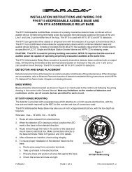
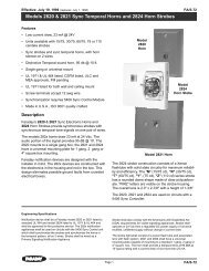
The <strong>8854</strong> utilizes the low-profile 8853 surface<br />
mounting base which may be used with a 4 inch<br />
square or octagonal box, as well as a single-gang<br />
electrical box. The <strong>8854</strong> has screw clamp terminals<br />
for easy wiring. The base has an optional concealed<br />
locking device to prevent unauthorized<br />
detector removal.<br />
The <strong>8854</strong> is capable of operating both a remote<br />
lamp <strong>and</strong> a relay or audible base when used with<br />
LifeWatch-450 control panel, other panels will allow<br />
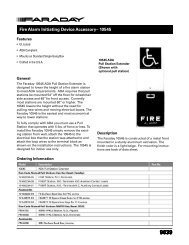
one accessory per detector. The 8848 Remote Sensitivity<br />
<strong>and</strong> Alarm indicator duplicates the multicolor<br />
LED of the detector at a remote location to indicate<br />
normal operation (green), trouble or out of sensitivity<br />
(amber), or alarm (red) for detectors located in out of<br />
the way places such as duct detectors, under computer<br />
room floors, or above suspended ceilings. The<br />
8849 is simply a remote red LED to indicate an alarm<br />
condition of a detector.<br />
The <strong>8843</strong> <strong>and</strong> <strong>8854</strong> <strong>and</strong> all of the above listed<br />
accessories are UL <strong>and</strong> ULC listed, <strong>and</strong> approved<br />
by CSFM <strong>and</strong> NYMEA, <strong>and</strong> other local boards<br />
where applicable.<br />
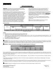
Application Data<br />
The <strong>8843</strong> <strong>and</strong> <strong>8854</strong> is fully compatible with other<br />
Faraday low voltage detectors <strong>and</strong> may be intermixed<br />
on the same conventional zone circuit. The<br />
<strong>8843</strong> <strong>and</strong> <strong>8854</strong> are applicable to the 30 foot spacing<br />
(900 sq. ft.) as referred to in the National Fire<br />
Protection Association St<strong>and</strong>ard 72. This detector<br />
spacing, however, is based on ideal conditions <strong>and</strong><br />
should be used only as a guide in planning detector<br />
layout. Do not mount detectors close to ventilation<br />
or air conditioning outlets that may move<br />
smoke away from the detector. Exposed joists or<br />
ceiling beams may also effect safe positioning of<br />
smoke detectors. It is m<strong>and</strong>atory that engineering<br />
judgement be applied regarding detector placement<br />
<strong>and</strong> spacing.<br />
Detector Cleaning<br />
The detector is field cleanable by twisting the<br />
detector out of the base, unsnapping the chamber<br />
from the outer cover, without affecting sensitive<br />
calibration <strong>and</strong> cleaning or replacing the removable<br />
chamber labyrinth <strong>and</strong> bug screen.<br />
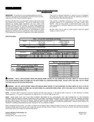
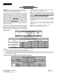
Architect <strong>and</strong> Engineer Specifications<br />
The photoelectric smoke detector shall be a plug-in<br />
unit which mounts to a twist/in base <strong>and</strong> shall be<br />
UL listed.<br />
The smoke detector shall operate on a two-wire<br />
circuit <strong>and</strong> shall contain a multicolor LED indicator<br />
indicating the detector is operational by flashing<br />
green, trouble by flashing amber, <strong>and</strong> alarm by<br />
flashing red. The detector shall be continually self<br />
testing with visual operation indication <strong>and</strong> not<br />
require additional hardware or contact with the<br />
detector for testing purposes.<br />
The detector shall allow for easy cleaning or<br />
replacement of screens <strong>and</strong>/or chamber components<br />
without affecting calibration.<br />
The base assembly into which the detector is<br />
installed shall be a twist/in design with screw<br />
clamp terminals. A security lock shall be installed<br />
in those areas where tamper resistant installation is<br />
required as indicated in the drawings.<br />
The detector or group of detectors shall require a<br />
two-wire circuit of #18 AWG thermoplastic fixture<br />
wire enclosed in conduit, or #18 AWG limited<br />
energy shielded cable without conduit, if permitted<br />
by local building codes. All wiring shall be approved<br />
for fire alarm use <strong>and</strong> in compliance with<br />
national <strong>and</strong> local codes. When required, the smoke<br />
detector shall contain a 135°F fixed temperature<br />
self restoring heat sensor. Actuation of this device<br />
shall lock the detector alarm circuit.<br />
The detector shall be Faraday Model <strong>8854</strong> or Model<br />
<strong>8843</strong> with a 8853 surface mounting base.