8843 and 8854 Photoelectric Smoke Detectors - Siemens Building ...
8843 and 8854 Photoelectric Smoke Detectors - Siemens Building ...
8843 and 8854 Photoelectric Smoke Detectors - Siemens Building ...

Create successful ePaper yourself
Turn your PDF publications into a flip-book with our unique Google optimized e-Paper software.
<strong>8843</strong> <strong>and</strong> <strong>8854</strong> <strong>Photoelectric</strong> <strong>Smoke</strong> <strong>Detectors</strong><br />
Features<br />
• Advanced Field Cleanable Chamber Design<br />
• Self Diagnostic<br />
• Multi-Color LED for Normal, Trouble or Alarm Indication<br />
• Low-Profile Design<br />
• Easy Twist-In Base Design<br />
• ISO 9001 Certified<br />
• UL Listed, no. S6082<br />
• Made in U.S.A.<br />
Introduction<br />
The Faraday <strong>8843</strong> <strong>and</strong> <strong>8854</strong> <strong>Photoelectric</strong> <strong>Smoke</strong><br />
<strong>Detectors</strong>, with its microprocessor controlled selfdiagnostic<br />
circuitry, eliminates cumbersome<br />
sensitivity test equipment. It is the most advanced<br />
detector in its class. This detector employs a simple<br />
twist-in base for ease of maintenance <strong>and</strong> has a<br />
field cleanable/replaceable labyrinth <strong>and</strong> bug<br />
screen. This detector is highly immune to false<br />
alarm caused by deceptive phenomena such as<br />
dust or RF. These detectors have a full range of<br />
accessories available, including remote alarm<br />
indicator, remote sensitivity <strong>and</strong> alarm indicator,<br />
relay <strong>and</strong> audible base adapters, <strong>and</strong> a base<br />
adapter that allows use in older Faraday 8914<br />
Series bases.<br />
Description<br />
The <strong>8843</strong>/<strong>8854</strong> is a two-wire, plug-in type photoelectric<br />
smoke detector which is compatible with<br />
Faraday’s FireWatch-200, FireWatch-400, LifeWatch-<br />
401 <strong>and</strong> LifeWatch-450 conventional systems.<br />
The <strong>8843</strong>/<strong>8854</strong> contains an infrared light emitting<br />
diode (LED) <strong>and</strong> a light sensing photodiode arranged<br />
so that under normal conditions, light from<br />
the LED does not reach the photodiode. When<br />
smoke enters the photo chamber, light emitted<br />
from the IR LED is scattered by the smoke particles<br />
<strong>and</strong> is received by the photodiode. The electrical<br />
signal produced by the photodiode is compared to<br />
a factory set alarm threshold, <strong>and</strong> if sufficient to<br />
indicate an alarm, latches the detector alarm. The<br />
<strong>8843</strong>/ <strong>8854</strong> is reset at the control panel.<br />
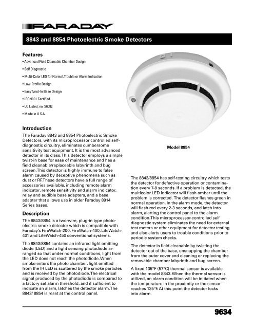
Model <strong>8854</strong><br />
The <strong>8843</strong>/<strong>8854</strong> has self-testing circuitry which tests<br />
the detector for defective operation or contamination<br />
every 7-8 seconds. If a problem is detected, the<br />
multicolor LED indicator will flash amber until the<br />
problem is corrected. The detector flashes green in<br />
normal operation. In the alarm mode, the detector<br />
will flash red every 2-3 seconds, <strong>and</strong> latch into<br />
alarm, alerting the control panel to the alarm<br />
condition. This microprocessor-controlled self<br />
diagnostic system eliminates the need for external<br />
test meters or other equipment for detector testing<br />
<strong>and</strong> also alerts users to trouble conditions prior to<br />
periodic system checks.<br />
The detector is field cleanable by twisting the<br />
detector out of the base, unsnapping the chamber<br />
from the outer cover <strong>and</strong> cleaning or replacing the<br />
removable chamber labyrinth <strong>and</strong> bug screen.<br />
A fixed 135°F (57°C) thermal sensor is available<br />
with the model <strong>8843</strong>. When the thermal sensor is<br />
utilized, an alarm condition will be initiated when<br />
the temperature in the proximity or the sensor<br />
reaches 135°F. At this point the detector locks<br />
into alarm.<br />
9634
The <strong>8854</strong> utilizes the low-profile 8853 surface<br />
mounting base which may be used with a 4 inch<br />
square or octagonal box, as well as a single-gang<br />
electrical box. The <strong>8854</strong> has screw clamp terminals<br />
for easy wiring. The base has an optional concealed<br />
locking device to prevent unauthorized<br />
detector removal.<br />
The <strong>8854</strong> is capable of operating both a remote<br />
lamp <strong>and</strong> a relay or audible base when used with<br />
LifeWatch-450 control panel, other panels will allow<br />
one accessory per detector. The 8848 Remote Sensitivity<br />
<strong>and</strong> Alarm indicator duplicates the multicolor<br />
LED of the detector at a remote location to indicate<br />
normal operation (green), trouble or out of sensitivity<br />
(amber), or alarm (red) for detectors located in out of<br />
the way places such as duct detectors, under computer<br />
room floors, or above suspended ceilings. The<br />
8849 is simply a remote red LED to indicate an alarm<br />
condition of a detector.<br />
The <strong>8843</strong> <strong>and</strong> <strong>8854</strong> <strong>and</strong> all of the above listed<br />
accessories are UL <strong>and</strong> ULC listed, <strong>and</strong> approved<br />
by CSFM <strong>and</strong> NYMEA, <strong>and</strong> other local boards<br />
where applicable.<br />
Application Data<br />
The <strong>8843</strong> <strong>and</strong> <strong>8854</strong> is fully compatible with other<br />
Faraday low voltage detectors <strong>and</strong> may be intermixed<br />
on the same conventional zone circuit. The<br />
<strong>8843</strong> <strong>and</strong> <strong>8854</strong> are applicable to the 30 foot spacing<br />
(900 sq. ft.) as referred to in the National Fire<br />
Protection Association St<strong>and</strong>ard 72. This detector<br />
spacing, however, is based on ideal conditions <strong>and</strong><br />
should be used only as a guide in planning detector<br />
layout. Do not mount detectors close to ventilation<br />
or air conditioning outlets that may move<br />
smoke away from the detector. Exposed joists or<br />
ceiling beams may also effect safe positioning of<br />
smoke detectors. It is m<strong>and</strong>atory that engineering<br />
judgement be applied regarding detector placement<br />
<strong>and</strong> spacing.<br />
Detector Cleaning<br />
The detector is field cleanable by twisting the<br />
detector out of the base, unsnapping the chamber<br />
from the outer cover, without affecting sensitive<br />
calibration <strong>and</strong> cleaning or replacing the removable<br />
chamber labyrinth <strong>and</strong> bug screen.<br />
Architect <strong>and</strong> Engineer Specifications<br />
The photoelectric smoke detector shall be a plug-in<br />
unit which mounts to a twist/in base <strong>and</strong> shall be<br />
UL listed.<br />
The smoke detector shall operate on a two-wire<br />
circuit <strong>and</strong> shall contain a multicolor LED indicator<br />
indicating the detector is operational by flashing<br />
green, trouble by flashing amber, <strong>and</strong> alarm by<br />
flashing red. The detector shall be continually self<br />
testing with visual operation indication <strong>and</strong> not<br />
require additional hardware or contact with the<br />
detector for testing purposes.<br />
The detector shall allow for easy cleaning or<br />
replacement of screens <strong>and</strong>/or chamber components<br />
without affecting calibration.<br />
The base assembly into which the detector is<br />
installed shall be a twist/in design with screw<br />
clamp terminals. A security lock shall be installed<br />
in those areas where tamper resistant installation is<br />
required as indicated in the drawings.<br />
The detector or group of detectors shall require a<br />
two-wire circuit of #18 AWG thermoplastic fixture<br />
wire enclosed in conduit, or #18 AWG limited<br />
energy shielded cable without conduit, if permitted<br />
by local building codes. All wiring shall be approved<br />
for fire alarm use <strong>and</strong> in compliance with<br />
national <strong>and</strong> local codes. When required, the smoke<br />
detector shall contain a 135°F fixed temperature<br />
self restoring heat sensor. Actuation of this device<br />
shall lock the detector alarm circuit.<br />
The detector shall be Faraday Model <strong>8854</strong> or Model<br />
<strong>8843</strong> with a 8853 surface mounting base.
Technical Specifications<br />
Current Requirements:<br />
Normal -100 uA peak<br />
Alarm - 40 mA<br />
Voltage Range:<br />
16 - 26.6 Vdc<br />
Operating Temperature:<br />
32-102°F (0-39°C)<br />
Humidity:<br />
93% non-condensing<br />
Shipping Weight:<br />
<strong>8843</strong>, 8 oz. approx.<br />
<strong>8854</strong>, 8 oz. approx.<br />
Dimensions<br />
Wiring<br />
Caution:<br />
1. Do not use looped wire under base terminal 5.<br />
Break wire run to provide supervision of connection.<br />
2.When a remote relay is used to control a critical<br />
system function, the relay <strong>and</strong> it’s associated<br />
detector <strong>and</strong> optional module(s) must be the only<br />
devices on the initiating circuit.
Ordering Information<br />
<strong>Siemens</strong> <strong>Building</strong> Technologies, Inc.<br />
8 Fernwood Road • Florham Park, NJ 07932<br />
Tel: (973) 593-2600 • Fax: (973) 593-6670<br />
Web: www.faradayfirealarms.com<br />
10/05 2M SBT/IG<br />
WARNING<br />
- The information contained in this document is intended only as a summary <strong>and</strong><br />
is subject to change without notice. The devices described in this document have specific<br />
instruction sheets which cover various technical, limitation <strong>and</strong> liability information. Copies<br />
of these instruction sheets <strong>and</strong> the General Product Warning <strong>and</strong> Limitations Document,<br />
which also contains important information, are provided with the product <strong>and</strong> are available<br />
from the Manufacturer. Information contained in these documents should be consulted<br />
before specifying or using the product. For further information or assistance concerning<br />
particular problems contact the Manufacturer.<br />
October 2005 - Supersedes sheet dated 12/03