Installation Instructions for 6300, 6301, 6310 and 6311 ... - Faraday
Installation Instructions for 6300, 6301, 6310 and 6311 ... - Faraday
Installation Instructions for 6300, 6301, 6310 and 6311 ... - Faraday

You also want an ePaper? Increase the reach of your titles
YUMPU automatically turns print PDFs into web optimized ePapers that Google loves.
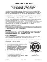
<strong>Installation</strong> <strong>Instructions</strong> <strong>for</strong><br />
<strong>6300</strong>, <strong>6301</strong>, <strong>6310</strong> <strong>and</strong> <strong>6311</strong> Electronic Signal<br />
<strong>and</strong> 6304, <strong>and</strong> 6314 Electronic Signal W/Adapter Strobe<br />
(Selectable C<strong>and</strong>ela / Sync/Non-Sync Strobe)<br />
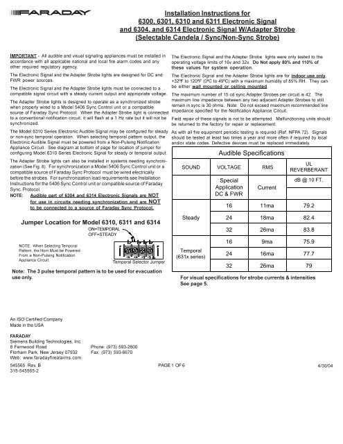
IMPORTANT - All audible <strong>and</strong> visual signaling appliances must be installed in<br />
accordance with all applicable national <strong>and</strong> local fire alarm codes <strong>and</strong> any<br />
other required regulatory agency<br />
The Electronic Signal <strong>and</strong> the Adapter Strobe lights are designed <strong>for</strong> DC <strong>and</strong><br />
FWR power sources<br />
The Electronic Signal <strong>and</strong> the Adapter Strobe lights must be connected to a<br />
compatible signal circuit with a steady current output <strong>and</strong> appropriate voltage<br />
The Adapter Strobe lights is designed to operate as a synchronized strobe<br />
when properly wired to a Model 5406 Sync Control unit or a compatible<br />
source of <strong>Faraday</strong> Sync Protocol When the Adapter Strobe light is connected<br />
to a conventional notification circuit, it will flash at a 1 Hz rate but it will not be<br />
synchronized<br />
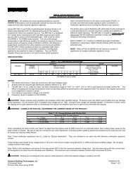
The Model <strong>6310</strong> Series Electronic Audible Signal may be configured <strong>for</strong> steady<br />
or non-sync temporal operation When selecting temporal pattern output, the<br />
Electronic Audible Signal must be powered from a Non-Pulsing Notification<br />
Appliance Circuit See diagram at bottom of page <strong>for</strong> location of jumper <strong>for</strong><br />
configuring Model <strong>6310</strong> Series Electronic Signal <strong>for</strong> steady or temporal output<br />
The Adapter Strobe lights can also be installed in systems needing synchronization<br />
(See Fig 8) For synchronization a Model 5406 Sync Control unit or a<br />
compatible source of <strong>Faraday</strong> Sync Protocol must be wired electrically<br />
be<strong>for</strong>e the strobes For synchronization load requirements see <strong>Installation</strong><br />
<strong>Instructions</strong> <strong>for</strong> the 5406 Sync Control unit or compatible source of <strong>Faraday</strong><br />
Sync Protocol<br />
NOTE: Audible part of 6304 <strong>and</strong> 6314 Electronic Signals are NOT<br />
<strong>for</strong> use in circuits needing synchronization <strong>and</strong> are NOT<br />
to be connected to a source of <strong>Faraday</strong> Sync Protocol<br />
Jumper Location <strong>for</strong> Model <strong>6310</strong>, <strong>6311</strong> <strong>and</strong> 6314<br />
NOTE: When Selecting Temporal<br />
Pattern, the Horn Must be Powered<br />
From a Non-Pulsing Notification<br />
Appliance Circuit<br />
ON=TEMPORAL<br />
OFF=STEADY<br />
Temporal Selector Jumper<br />
Note: The 3 pulse temporal pattern is to be used <strong>for</strong> evacuation<br />
use only<br />
The Electronic Signal <strong>and</strong> the Adapter Strobe lights were only tested to the<br />
operating voltage limits of 16v <strong>and</strong> 32v Do Not apply 80% <strong>and</strong> 110% of<br />
these values <strong>for</strong> system operation<br />
The Electronic Signal <strong>and</strong> the Adapter Strobe lights are <strong>for</strong> indoor use only,<br />
+32ºF to 120ºF (0ºC to 49ºC) with a maximum humidity of 85% RH They can<br />
be either wall mounted or ceiling mounted<br />
The maximum number of 15 cd sync Adapter Strobes per circuit is 42 The<br />
maximum line impedance between any two adjacent Adapter Strobes to still<br />
remain in sync is 30 ohms Note: Do not exceed maximum recommended line<br />
impedance specified <strong>for</strong> the Notification Appliance Circuit<br />
Field repair of these signals is not to be attempted Malfunctioning units should<br />
be returned to the factory <strong>for</strong> repair or replacement<br />
As with all fire equipment periodic testing is required (Ref NFPA 72) Signals<br />
should be tested at least two times a year <strong>and</strong> more often if required by local<br />
<strong>and</strong>/or state codes Defective devices must be replaced immediately<br />
Audible Specifications<br />
SOUND VOLTAGE RMS<br />
Steady<br />
Temporal<br />
(631x series)<br />
Special<br />
Application<br />
DC & FWR<br />
Current<br />
UL<br />
REVERBERANT<br />
dB @ 10 FT.<br />
16 11ma 79.2<br />
24 18ma 82.4<br />
32 26ma 83.8<br />
16 9ma 75.9<br />
24 16ma 77.7<br />
32 26ma 79<br />
For visual specifications <strong>for</strong> strobe currents & intensities<br />
See page 5<br />
An ISO Certified Company<br />
Made in the USA<br />
FARADAY<br />
Siemens Building Technologies, Inc<br />
8 Fernwood Road Phone: (973) 593-2600<br />
Florham Park, New Jersey 07932 Fax: (973) 593-6670<br />
Web: wwwfaradayfirealarmscom<br />
545565 Rev B<br />
315-545565-2<br />
PAGE 1 OF 6 4/30/04
<strong>6300</strong> or <strong>6310</strong> ELECTRONIC SIGNAL (Fig 1)<br />
1 For <strong>6310</strong> Electronic Signal, configure Electronic Signal <strong>for</strong><br />
temporal or steady tone (see diagram on page 1)<br />
2 Connect wiring (see fig 4)<br />
3 Mount the Electronic Signal to the single gang box with the two<br />
# 6-32 x 1-3/4" screws<br />
4 Test unit <strong>for</strong> proper operation<br />
<strong>6301</strong> or <strong>6311</strong> ELECTRONIC SIGNAL (Fig 2)<br />
1 For <strong>6311</strong> Electronic Signal, configure Electronic Signal <strong>for</strong><br />
temporal or steady tone (see diagram on page 1)<br />
2 Pull the wires from the outlet box through the large opening in the<br />
adapter plate<br />
3 Mount the adapter plate to the electrical box using the appropriate<br />
screws provided Making sure that the adapter plate is mounted in<br />
the upright position<br />
(Note: When using a single gang outlet box make sure to use the holes<br />
labelled "single gang")<br />
4 Connect wiring (see fig 5)<br />
5 Mount the grill on to the adapter plate by first engaging the two<br />
slots in the bottom of the grille with the two tabs in the bottom of<br />
the adapter<br />
6 Test unit <strong>for</strong> proper operation<br />
Mounting <strong>Instructions</strong><br />
Wiring Note: Individual wires (especially heavy gauge wire) should be bent at 90° be<strong>for</strong>e attaching to screw Wiring should then<br />
carefully be pushed back into back box to minimize stress on the terminal block<br />
(2) 6-32 x 1-3/4"<br />
Screws<br />
#6 x 1-1/4"<br />
Self<br />
Tapping<br />
Screw<br />
Fig 1<br />
(<strong>6300</strong> or <strong>6310</strong>)<br />
(2) 8-32<br />
x 1/2"<br />
Screws<br />
OR<br />
(2) 6-32<br />
x 5/8"<br />
Screws<br />
(4) 6-32 x<br />
5/8" Screws<br />
OR<br />
Fig 2 (<strong>6301</strong> or <strong>6311</strong>)<br />
6304 or 6314 ELECTRONIC SIGNAL/STROBE (Fig 3)<br />
1 For 6314 Electronic Signal w/Strobe, configure Electronic Signal <strong>for</strong><br />
temporal or steady tone (see diagram on page 1)<br />
2 Move Strobe C<strong>and</strong>ela Selection Switch to desired setting<br />
(see diagram page 5)<br />
3 Place supplied hole plug (P/N 944276) in <strong>for</strong> hole <strong>for</strong> Strobe<br />
C<strong>and</strong>ela Selection Switch<br />
4 Pull the wires from the outlet box through the large<br />
opening in the adapter plate<br />
5 Mount the adapter plate to the electrical box using the<br />
appropriate screws provided Making sure that the adapter<br />
plate is mounted in the upright position<br />
(Note: When using a single gang outlet box make sure to use<br />
the holes labelled "single gang")<br />
6 Configure <strong>and</strong> wire the 6304 or 6314 <strong>for</strong> either single circuit or split<br />
audible/strobe operation (see fig 6, fig 7 or fig 8)<br />
(Note: Split operation requires two separate notification circuits)<br />
(Note: Audible part of 6304 <strong>and</strong> 6314 Electronic Signals are not<br />
<strong>for</strong> use in circuits needing synchronization <strong>and</strong> are not<br />
to be connected to source of <strong>Faraday</strong> Sync Protocol)<br />
7 Mount the grille on to the adapter plate by first engaging the two<br />
slots in the bottom of the grille with the two tabs in the bottom of the<br />
adapter plate Then use the # 6 x 5/8" self tapping screw to attach<br />
the grill to the adapter plate<br />
8 Test unit <strong>for</strong> proper operation<br />
TIGHTEN SCREW UNTIL SNUG<br />
DO NOT OVERTIGHTEN<br />
#6 x 5/8"<br />
Self<br />
Tapping<br />
Screw<br />
(2) 8-32<br />
x 1/2"<br />
Screws<br />
OR<br />
(2) 6-32<br />
x 5/8"<br />
Screws<br />
OR<br />
Fig 3 (6304 or 6314)<br />
Supplied Hole Plug (P/N 944276)<br />
Place Hole Plug in hole <strong>for</strong> Strobe C<strong>and</strong>ela<br />
Selection Switch after moving C<strong>and</strong>ela<br />
Selection Switch to desired c<strong>and</strong>ela rating<br />
position<br />
(4) 6-32 x<br />
5/8" Screws<br />
545565 Rev B<br />
315-545565-2<br />
PAGE 2 OF 6<br />
4/30/04
Wiring Diagram <strong>for</strong><br />
<strong>6300</strong> or <strong>6310</strong> Electronic Audible Signal<br />
(Non-Sync Circuit)<br />
Wiring Diagrams<br />
NOTE: UNITS TO BE ONLY INSTALLED IN ACCORDANCE WITH THE NATIONAL ELECTRICAL CODE AND LOCAL ELECTRICAL CODES<br />
DO NOT LOOP WIRE, CUT WIRE RUN TO PROVIDE ELECTRICAL SUPERVISION<br />
Terminals are designed to accept no larger than 12 ga wire<br />
Wiring Diagram <strong>for</strong><br />
<strong>6301</strong> or <strong>6311</strong> Electronic Audible Signal<br />
(Non-Sync Circuit)<br />
Individual wires (especially heavy<br />
gauge wire) should be bent at 90°<br />
be<strong>for</strong>e attaching to screw Wiring<br />
should then carefully be pushed<br />
back into back box to minimize<br />
stress on the terminal block<br />
FROM CONTROL<br />
PANEL OR<br />
PREVIOUS DEVICE<br />
TO NEXT<br />
DEVICE<br />
OR EOL<br />
FROM CONTROL<br />
PANEL OR<br />
PREVIOUS DEVICE<br />
TO NEXT<br />
DEVICE<br />
OR EOL<br />
AUDIBLE<br />
NOTIFICATION<br />
APPLIANCE CKT<br />
ALARM POLARITY SHOWN<br />
AUDIBLE<br />
NOTIFICATION<br />
APPLIANCE CKT<br />
ALARM POLARITY SHOWN<br />
Fig 4 Fig 5<br />
Wiring Diagram <strong>for</strong> 6304 or 6314 Electronic Audible Signal w/Strobe<br />
When Signal <strong>and</strong> Non-Sync Strobe are Connected to Same Notification Appliance Circuit<br />
Individual wires (especially heavy<br />
gauge wire) should be bent at 90°<br />
be<strong>for</strong>e attaching to screw Wiring<br />
should then carefully be pushed<br />
back into back box to minimize<br />
stress on the terminal block<br />
LEAVE JUMPERS IN PLACE<br />
(STROBE AND AUDIBLE SIGNAL<br />
ARE TO OPERATE ON THE SAME<br />
CIRCUIT)<br />
NOTE: STROBES MUST BE<br />
CONNECTED TO A NON-PULSING<br />
NOTIFICATION APPLIANCE CKT<br />
FROM CONTROL PANEL<br />
OR PREVIOUS DEVICE<br />
TO NEXT DEVICE OR EOL<br />
ALARM POLARITY SHOWN<br />
NOTE:<br />
NOTIFICATION<br />
APPLIANCE CKT<br />
+<br />
-<br />
+<br />
-<br />
WHEN AUDIBLE SIGNAL AND STROBE ARE CONNECTED TO SAME NOTIFICATION APPLIANCE CIRCUIT,<br />
CURRENT RATING IS COMBINATION OF AUDIBLE SIGNAL AND STROBE CURRENT<br />
Fig 6<br />
545565 Rev B<br />
315-545565-2<br />
PAGE 3 OF 6 4/30/04
NOTE: UNITS TO BE ONLY INSTALLED IN ACCORDANCE<br />
WITH THE NATIONAL ELECTRICAL CODE AND LOCAL<br />
ELECTRICAL CODES<br />
FROM CONTROL PANEL<br />
OR PREVIOUS DEVICE<br />
STROBE NOTIFICATION<br />
APPLIANCE CKT<br />
AUDIBLE NOTIFICATION<br />
APPLIANCE CKT<br />
+ -<br />
+ -<br />
Wiring Diagrams<br />
Fig 7<br />
From control panel steady (non-pulsing or pulsing) silenceable<br />
Notification Appliance Circuit or previous silenceable notification appliance<br />
From control panel steady (non-pulsing) non-silenceable<br />
Notification Appliance Circuit (NAC) or previous notification appliance<br />
DO NOT LOOP WIRE, CUT WIRE RUN TO PROVIDE<br />
ELECTRICAL SUPERVISION<br />
Terminals are designed to accept no larger than 12 ga wire<br />
Wiring Diagram <strong>for</strong> 6304 or 6314 Electronic Audible Signal w/Strobe<br />
When Signal <strong>and</strong> Non-Sync Strobe are Connected to Two Separate Notification Appliance Circuits<br />
Wiring Diagram <strong>for</strong> 6304 or 6314 Electronic Audible Signal w/Strobe<br />
When Strobe is Connected to 5406 Sync Control Module<br />
CUT JUMPERS (AUDIBLE<br />
SIGNAL AND STROBE ON<br />
SEPARATE CIRCUITS)<br />
NOTE: STROBES MUST BE<br />
CONNECTED TO A NON-PULSING<br />
NOTIFICATION APPLIANCE CKT<br />
TO NEXT DEVICE OR EOL<br />
+<br />
-<br />
+<br />
-<br />
ALARM POLARITY SHOWN<br />
Individual wires (especially heavy<br />
gauge wire) should be bent at 90°<br />
be<strong>for</strong>e attaching to screw Wiring<br />
should then carefully be pushed<br />
back into back box to minimize<br />
stress on the terminal block<br />
CUT JUMPERS<br />
(STROBE ON SYNC<br />
STROBE CIRCUIT)<br />
5406<br />
16-32 V<br />
DC or FWR<br />
20ma<br />
SUPERVISED AND<br />
POWERED BY<br />
NON-SILENCEABLE<br />
NAC FROM FIRE<br />
ALARM CONTROL UNIT<br />
FROM CONTROL PANEL<br />
AUDIBLE NAC OR<br />
PREVIOUS AUDIBLE DEVICE<br />
Fig 8<br />
NOTE: STROBES MUST BE<br />
CONNECTED TO A<br />
NON-PULSING NOTIFICATION<br />
APPLIANCE CKT<br />
NOTE: Audible part of 6304 <strong>and</strong> 6314<br />
Electronic Signals are not <strong>for</strong> use in<br />
circuits needing synchronization <strong>and</strong><br />
are not to be connected to Model 5406<br />
Sync Control unit<br />
TO NEXT DEVICE<br />
OR EOL<br />
TO NEXT DEVICE<br />
OR EOL<br />
545565 Rev B<br />
315-545565-2<br />
PAGE 4 OF 6<br />
4/30/04
SPECIFICATIONS: Visual Signaling Appliance<br />
The Strobe C<strong>and</strong>ela Selection Switch Setting determines current draw<br />
Adjustment Switch Setting 15 30 75 110<br />
Listed UL 1971 Output 15 cd 30 cd 75 cd 110 cd<br />
Light Output, on Axis 75 cd 75 cd 75 cd 110 cd<br />
Operating Voltage Range Limits<br />
Special Application 16 - 32V DC or FWR<br />
DC FWR DC FWR DC FWR DC FWR<br />
*Maximum Operating RMS<br />
Current FWR & DC<br />
Rated Peak Current FWR &<br />
DC<br />
Initial Inrush<br />
Strobe Flash Rate<br />
16V 91 mA 112 mA 120 mA 139 mA 218 mA 251 mA 315 mA 323 mA<br />
24V 63 mA 82 mA 84 mA 107 mA 143 mA 182 mA 178 mA 234 mA<br />
32V 54 mA 75 mA 64 mA 94 mA 116 mA 142 mA 153 mA 183 mA<br />
16V 132 mA 264 mA 169 mA 272 mA 642 mA 668 mA 624 mA 652 mA<br />
24V 118 mA 278 mA 153 mA 298 mA 330 mA 668 mA 434 mA 636 mA<br />
32V 104 mA 664 mA 177 mA 668 mA 648 mA 682 mA 624 mA 666 mA<br />
Less than 840ma <strong>for</strong> 2 ms.<br />
1 Per Second<br />
15 cd <strong>and</strong> 30 cd Strobe switch settings were tested <strong>for</strong> 75 cd minimum on<br />
axis<br />
ADA Minimum Frontal Light Output requirement is 75 cd<br />
UL 1971 St<strong>and</strong>ard covers emergency signaling devices <strong>for</strong> the hearing<br />
impaired<br />
These strobe lights were only tested to the operating voltage limits of 16V<br />
<strong>and</strong> 32V Do Not apply 80% <strong>and</strong> 110% of these values <strong>for</strong> system operation<br />
The maximum number of 15 cd sync strobes per circuit is 42 The maximum<br />
line impedance between any two adjacent strobes to still remain in sync is<br />
30 ohms Note: Do not exceed maximum recommended line impedance<br />
specified <strong>for</strong> the Notification Appliance Circuit<br />
UL 1971 Visual Dispersion<br />
<strong>for</strong> Wall <strong>and</strong> Ceiling Mounting<br />
Degrees<br />
Minimum C<strong>and</strong>ela<br />
-15 -30 -75 -110<br />
0 75 75 75 110<br />
5 to 25 13.5 27 67.5 99<br />
30 to 45 11.25 22.5 56.25 82.5<br />
50 8.25 16.5 41.25 60.5<br />
55 6.75 13.5 33.75 49.5<br />
Strobe C<strong>and</strong>ela Selection<br />
Switch Location<br />
Supplied Hole Plug (P/N 944276)<br />
Place Hole Plug in hole <strong>for</strong> Strobe<br />
C<strong>and</strong>ela Selection Switch after<br />
moving C<strong>and</strong>ela Selection Switch<br />
to desired c<strong>and</strong>ela rating position 15<br />
c<strong>and</strong>ela<br />
30<br />
c<strong>and</strong>ela<br />
75<br />
c<strong>and</strong>ela<br />
110<br />
c<strong>and</strong>ela<br />
Switch Settings<br />
Factory Set at 15 C<strong>and</strong>ela<br />
Strobe C<strong>and</strong>ela Selection<br />
60 6 12 30 44<br />
65 5.25 10.5 26.25 38.5<br />
70 5.25 10.5 26.25 38.5<br />
75 4.5 9 22.5 33<br />
80 4.5 9 22.5 33<br />
85 3.75 7.5 18.75 27.5<br />
90 3.75 7.5 18.75 27.5<br />
545565 Rev B<br />
315-545565-2<br />
PAGE 5 OF 6 4/30/04
Siemens Building Technologies, Inc<br />
8 Fernwood Road, Florham Park, New Jersey 07932<br />
Phone: (973) 593-2600 / Fax: (973) 593-6670<br />
Web: wwwfaradayfirealarmscom<br />
An ISO Certified Company<br />
Made in the USA<br />
545565 Rev B<br />
315-545565-2<br />
PAGE 6 OF 6<br />
4/30/04