8839 and 8840 Duct Smoke Detector Housings - Siemens Building ...
8839 and 8840 Duct Smoke Detector Housings - Siemens Building ...
8839 and 8840 Duct Smoke Detector Housings - Siemens Building ...

You also want an ePaper? Increase the reach of your titles
YUMPU automatically turns print PDFs into web optimized ePapers that Google loves.
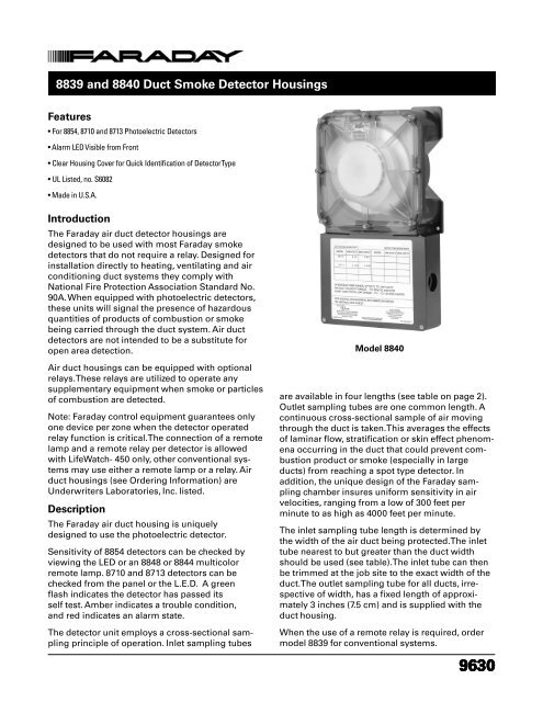
<strong>8839</strong> <strong>and</strong> <strong>8840</strong> <strong>Duct</strong> <strong>Smoke</strong> <strong>Detector</strong> <strong>Housings</strong><br />
Features<br />
• For 8854, 8710 <strong>and</strong> 8713 Photoelectric <strong>Detector</strong>s<br />
• Alarm LED Visible from Front<br />
• Clear Housing Cover for Quick Identification of <strong>Detector</strong> Type<br />
• UL Listed, no. S6082<br />
• Made in U.S.A.<br />
Introduction<br />
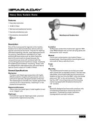
The Faraday air duct detector housings are<br />
designed to be used with most Faraday smoke<br />
detectors that do not require a relay. Designed for<br />
installation directly to heating, ventilating <strong>and</strong> air<br />
conditioning duct systems they comply with<br />
National Fire Protection Association St<strong>and</strong>ard No.<br />
90A. When equipped with photoelectric detectors,<br />
these units will signal the presence of hazardous<br />
quantities of products of combustion or smoke<br />
being carried through the duct system. Air duct<br />
detectors are not intended to be a substitute for<br />
open area detection.<br />
Air duct housings can be equipped with optional<br />
relays. These relays are utilized to operate any<br />
supplementary equipment when smoke or particles<br />
of combustion are detected.<br />
Note: Faraday control equipment guarantees only<br />
one device per zone when the detector operated<br />
relay function is critical. The connection of a remote<br />
lamp <strong>and</strong> a remote relay per detector is allowed<br />
with LifeWatch- 450 only, other conventional systems<br />
may use either a remote lamp or a relay. Air<br />
duct housings (see Ordering Information) are<br />
Underwriters Laboratories, Inc. listed.<br />
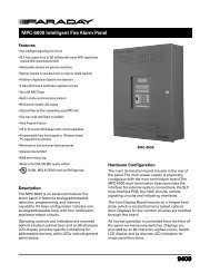
Description<br />
The Faraday air duct housing is uniquely<br />
designed to use the photoelectric detector.<br />
Sensitivity of 8854 detectors can be checked by<br />
viewing the LED or an 8848 or 8844 multicolor<br />
remote lamp. 8710 <strong>and</strong> 8713 detectors can be<br />
checked from the panel or the L.E.D. A green<br />
flash indicates the detector has passed its<br />
self test. Amber indicates a trouble condition,<br />
<strong>and</strong> red indicates an alarm state.<br />
The detector unit employs a cross-sectional sampling<br />
principle of operation. Inlet sampling tubes<br />
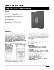
Model <strong>8840</strong><br />
are available in four lengths (see table on page 2).<br />
Outlet sampling tubes are one common length. A<br />
continuous cross-sectional sample of air moving<br />
through the duct is taken. This averages the effects<br />
of laminar flow, stratification or skin effect phenomena<br />
occurring in the duct that could prevent combustion<br />
product or smoke (especially in large<br />
ducts) from reaching a spot type detector. In<br />
addition, the unique design of the Faraday sampling<br />
chamber insures uniform sensitivity in air<br />
velocities, ranging from a low of 300 feet per<br />
minute to as high as 4000 feet per minute.<br />
The inlet sampling tube length is determined by<br />
the width of the air duct being protected. The inlet<br />
tube nearest to but greater than the duct width<br />
should be used (see table). The inlet tube can then<br />
be trimmed at the job site to the exact width of the<br />
duct. The outlet sampling tube for all ducts, irrespective<br />
of width, has a fixed length of approximately<br />
3 inches (7.5 cm) <strong>and</strong> is supplied with the<br />
duct housing.<br />
When the use of a remote relay is required, order<br />
model <strong>8839</strong> for conventional systems.<br />
9630
Sampling Tube Selection<br />
Maintenance of the detector is easily accomplished<br />
by the removal of the duct housing sampling<br />
chamber cover. The detector, which plugs into the<br />
housing, is easily removed for cleaning by a trained<br />
technician. All that is necessary for the installation<br />
of the air duct detector is the cutting of three small<br />
holes for the sampling tube installation (template<br />
included) <strong>and</strong> the drilling of four holes for mounting<br />
the air duct housing. The unit is then easily<br />
mounted in place <strong>and</strong> connection made to the<br />
existing wires or terminals if optional accessories<br />
are utilized. See chart below for sampling tube<br />
selection table.<br />
<strong>Duct</strong> Width<br />
Model No.<br />
9" to 21" (23 cm to 53 cm) 8932B<br />
21" to 39" (53 cm to 99 cm) 8933B<br />
39" to 75" (99 cm to 191 cm) 8934B<br />
75" to 117" (191 cm to 297 cm) 8935B<br />
Greater than 117" (297 cm) Consult Faraday<br />
Engineer <strong>and</strong> Architect Specifications<br />
The air duct housing for the fire detection system<br />
shall be a Faraday <strong>8839</strong> or <strong>8840</strong> air duct housing.<br />
The air duct housing shall incorporate the use of<br />
the 8854, 8710 <strong>and</strong> 8713 detectors.<br />
The air duct housing unit shall be designed for<br />
detection of combustion products <strong>and</strong>/or smoke in<br />
air conditioning <strong>and</strong> ventilation system ducts in<br />
compliance with NFPA St<strong>and</strong>ard 90A. The assembly<br />
shall consist of a housing to accommodate sampling<br />
tubes which extend into <strong>and</strong> across the duct<br />
of the ventilation system.<br />
While the fans are operating, a continuous crosssectional<br />
sampling of air from the duct shall flow<br />
through the photoelectric detector, after which the<br />
sampled air shall be returned to the duct. Air<br />
h<strong>and</strong>ling equipment shall be shut down by a signal<br />
from the fire detection system control equipment.<br />
When the air duct housing incorporates the optional<br />
relay, the shut down of air h<strong>and</strong>ling devices<br />
may be accomplished by a signal directly from<br />
the detector.<br />
The air duct housing shall be available with a<br />
self-contained power supply so that it can function<br />
as a st<strong>and</strong>-alone unit if desired. The self-contained<br />
st<strong>and</strong>-alone unit will power <strong>and</strong> supervise two<br />
satellite units.<br />
The air duct housing shall utilize a plug-in<br />
detector head located in the air sampling chamber.<br />
The detector shall be photoelectric. There shall be<br />
provisions to check the detector sensitivity in place<br />
under actual air flow conditions.<br />
The air duct housing shall be mounted directly<br />
outside of the air duct by means of four bolts<br />
(supplied). A template shall be provided for making<br />
necessary cutouts <strong>and</strong> holes. Complete instructions<br />
shall be supplied with the unit.<br />
The air duct housing shall be a Faraday Model<br />
(See listing on back page) <strong>and</strong> shall be Underwriters<br />
Laboratories, Inc. Listed, specifically for use in<br />
air h<strong>and</strong>ling systems.<br />
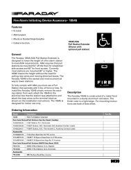
Note to Architect:<br />
When building codes regulate the location of<br />
detectors within ventilating systems, make sure<br />
that the number <strong>and</strong> locations of detectors are in<br />
accordance with the code regulations.
Technical Specifications<br />
Operating Temperature:<br />
32-100°F (0-38°C)<br />
Humidity:<br />
93% non-condensing<br />
Air <strong>Duct</strong> Velocity Range:<br />
300-4,000 ft./min - <strong>8839</strong> <strong>and</strong> <strong>8840</strong><br />
Sampling Tube Pressure Range of Differences:<br />
.01-1.0 inches of water column<br />
Shipping Weight:<br />
<strong>8839</strong>, 3 lbs. approx.<br />
<strong>8840</strong>, 3 lbs. approx.<br />
Dimensions<br />
Wiring<br />
Caution:<br />
1. Up to 30 air duct housings can be installed in<br />
any one circuit. However, when using 8843/8854<br />
detectors, limit the number of optional relays that<br />
perform individual functions to one per circuit<br />
because most control equipment can operate<br />
only one detector per circuit when in alarm.<br />
2. Do not use looped wire under base terminal 4.<br />
Break wire run to provide supervision of<br />
connection.<br />
Model <strong>8839</strong> only:<br />
1. When a duct housing relay is used to control<br />
a critical system function, the relay <strong>and</strong> it’s<br />
associated detector <strong>and</strong> optional module(s) must<br />
be the “only” devices on the initiating circuit.<br />
2. Do not use <strong>8839</strong> or detector operated accessories<br />
with LifeWatch-401.
Ordering Information<br />
<strong>Siemens</strong> <strong>Building</strong> Technologies, Inc.<br />
8 Fernwood Road • Florham Park, NJ 07932<br />
Tel: (973) 593-2600 • Fax: (973) 593-6670<br />
Web: www.faradayllc.com<br />
12/03 2M SBT/IG<br />
WARNING<br />
- The information contained in this document is intended only as a summary <strong>and</strong><br />
is subject to change without notice. The devices described in this document have specific<br />
instruction sheets which cover various technical, limitation <strong>and</strong> liability information. Copies<br />
of these instruction sheets <strong>and</strong> the General Product Warning <strong>and</strong> Limitations Document,<br />
which also contains important information, are provided with the product <strong>and</strong> are available<br />
from the Manufacturer. Information contained in these documents should be consulted<br />
before specifying or using the product. For further information or assistance concerning<br />
particular problems contact the Manufacturer.<br />
December 2003 - Supersedes sheet dated 6/98