MPC-6000 / MPC-7000 / RND-2 - Faraday
MPC-6000 / MPC-7000 / RND-2 - Faraday
MPC-6000 / MPC-7000 / RND-2 - Faraday

Create successful ePaper yourself
Turn your PDF publications into a flip-book with our unique Google optimized e-Paper software.
<strong>MPC</strong>-<strong>6000</strong> / <strong>MPC</strong>-<strong>7000</strong> / <strong>RND</strong>-2<br />
Fire Alarm System Control Unit<br />
Installation, Operation and Maintenance Manual<br />
Siemens Building Technologies, Inc.<br />
8 Fernwood Road • Florham Park, NJ 07932<br />
Tel: (973) 593-2600 • Fax: (973) 593-6670<br />
Web: www.faradayfirealarms.com<br />
P/N 315-447309-7 (12.07.07) 9 th Edition
TABLE OF CONTENTS<br />
INTRODUCTION........................................................................................................................................................1<br />
CONTROL UNIT LIMITATIONS ............................................................................................................................1<br />
INSTALLATION AND WARRANTY INFORMATION.............................................................................................2<br />
Installer Information:............................................................................................................................................2<br />
Original Purchaser Information:...........................................................................................................................2<br />
PREFACE..............................................................................................................................................................3<br />
<strong>MPC</strong>-<strong>6000</strong> SYSTEM DESCRIPTION....................................................................................................................4<br />
Power Supply ......................................................................................................................................................4<br />
X1 Addressable Device Circuit............................................................................................................................4<br />
Notification Appliance Circuits.............................................................................................................................5<br />
Serial Interface Circuit.........................................................................................................................................5<br />
Status Relays ......................................................................................................................................................5<br />
Programming Port ...............................................................................................................................................5<br />
<strong>MPC</strong>-<strong>7000</strong> SYSTEM DESCRIPTION....................................................................................................................6<br />
Power Supply ......................................................................................................................................................6<br />
X1 Addressable Device Circuits..........................................................................................................................6<br />
Notification Appliance Circuits.............................................................................................................................7<br />
Serial Interface Circuit.........................................................................................................................................7<br />
Status Relays ......................................................................................................................................................7<br />
Programming Port ...............................................................................................................................................7<br />
<strong>RND</strong>-2 SYSTEM DESCRIPTION ..........................................................................................................................8<br />
Power Supply ......................................................................................................................................................8<br />
Serial Interface Circuit .........................................................................................................................................9<br />
Status Relays ......................................................................................................................................................9<br />
Programming Port ...............................................................................................................................................9<br />
OPTIONAL MODULES ........................................................................................................................................10<br />
CT-1K City Tie Board ........................................................................................................................................10<br />
<strong>MPC</strong>-DACT Board.............................................................................................................................................10<br />
NPE-1 Transformer Assembly...........................................................................................................................10<br />
NEM-1 NAC Expansion Board ..........................................................................................................................10<br />
LEM-1 Loop Expander Board ............................................................................................................................10<br />
FDLC Loop Driver Board...................................................................................................................................10<br />
HBC-1 Battery Charger .....................................................................................................................................10<br />
Battery Sets.......................................................................................................................................................11<br />
<strong>MPC</strong>-REL Releasing Module (<strong>MPC</strong>-<strong>6000</strong> Only) ...............................................................................................11<br />
12603A ..............................................................................................................................................................11<br />
12523A ..............................................................................................................................................................11<br />
12526A ..............................................................................................................................................................12<br />
12525.................................................................................................................................................................12<br />
12535.................................................................................................................................................................12<br />
12536.................................................................................................................................................................12<br />
AUXILIARY MODULES .......................................................................................................................................13<br />
Serial LCD Annunciators...................................................................................................................................13<br />
Serial Relay Unit and Serial Relay Extender.....................................................................................................13<br />
Serial Annunciator Unit and Serial Annunciator Extender ................................................................................13<br />
RSE-300 Remote Signal Expander ...................................................................................................................13<br />
X1 ADDRESSABLE DEVICES ............................................................................................................................14<br />
Fire Smart Smoke Detector ...........................................................................................................................14<br />
Heat Detectors...................................................................................................................................................14<br />
Addressable Modules (Monitor and Control).....................................................................................................14<br />
Manual Stations.................................................................................................................................................14<br />
i
Programming X1 Devices..................................................................................................................................14<br />
EVENT HISTORY ................................................................................................................................................15<br />
GENERAL DESIGN FEATURES ........................................................................................................................16<br />
Environmental....................................................................................................................................................16<br />
Power Limiting...................................................................................................................................................16<br />
Ground Fault Detection .....................................................................................................................................16<br />
NAC Operation ..................................................................................................................................................16<br />
Transient Protection ..........................................................................................................................................16<br />
Security Features ..............................................................................................................................................16<br />
REGULATORY STANDARDS.............................................................................................................................17<br />
Federal Communications Commission .............................................................................................................17<br />
Underwriters Laboratories.................................................................................................................................17<br />
GENERAL SPECIFICATIONS.............................................................................................................................18<br />
Environmental....................................................................................................................................................18<br />
Primary Supply ..................................................................................................................................................18<br />
Secondary Power Supply..................................................................................................................................18<br />
Auxiliary Power Outputs ....................................................................................................................................18<br />
Status Relays ....................................................................................................................................................18<br />
Notification Appliance Circuits...........................................................................................................................19<br />
Serial Interface Circuit.......................................................................................................................................19<br />
X1 Addressable Device Circuits........................................................................................................................19<br />
City Tie (Optional City Tie Board)......................................................................................................................19<br />
DACT Circuit (Optional DACT Board <strong>MPC</strong>-DACT) ...........................................................................................20<br />
Additional Transformer (Optional Transformer Sub-assembly NPE-1).............................................................20<br />
<strong>MPC</strong>-REL (Optional releasing module for <strong>MPC</strong>-<strong>6000</strong> only)..............................................................................21<br />
CONTROL UNIT OPERATION ................................................................................................................................22<br />
OPERATION INSTRUCTIONS............................................................................................................................22<br />
Standby Condition .............................................................................................................................................22<br />
Alarm Conditions...............................................................................................................................................22<br />
Trouble Conditions ............................................................................................................................................24<br />
Supervisory Conditions .....................................................................................................................................25<br />
Detector Pre-Alarm Conditions..........................................................................................................................25<br />
Fan Restart........................................................................................................................................................25<br />
Maintenance......................................................................................................................................................25<br />
ADDITIONAL OPERATING PROCEDURES ......................................................................................................26<br />
Lamp Test..........................................................................................................................................................26<br />
Drill ....................................................................................................................................................................26<br />
Recall.................................................................................................................................................................26<br />
Alert ...................................................................................................................................................................26<br />
Global Fan Restart ............................................................................................................................................27<br />
History ...............................................................................................................................................................27<br />
<strong>MPC</strong>-<strong>6000</strong> / <strong>MPC</strong>-<strong>7000</strong> / <strong>RND</strong>-2 OPERATING INSTRUCTIONS.......................................................................28<br />
Alarm Operation ................................................................................................................................................28<br />
Authorized Personnel Only................................................................................................................................28<br />
Trouble Operation .............................................................................................................................................28<br />
Event Scrolling...................................................................................................................................................28<br />
Normal Standby Condition ................................................................................................................................28<br />
RDC-2 / RDC-3 OPERATING INSTRUCTIONS .................................................................................................29<br />
Alarm Operation ................................................................................................................................................29<br />
Authorized Personnel Only................................................................................................................................29<br />
Trouble Operation .............................................................................................................................................29<br />
Event Scrolling...................................................................................................................................................29<br />
Normal Standby Condition ................................................................................................................................29<br />
<strong>MPC</strong>-<strong>6000</strong> / RDC-3 WITH RELEASING OPERATING INSTRUCTIONS...........................................................30<br />
Alarm Operation ................................................................................................................................................30<br />
Authorized Personnel Only................................................................................................................................30<br />
Trouble Operation .............................................................................................................................................30<br />
ii
Event Scrolling...................................................................................................................................................30<br />
Normal Standby Condition ................................................................................................................................30<br />
CONTROL UNIT INSTALLATION ...........................................................................................................................31<br />
PARTS SUPPLIED – <strong>MPC</strong>-<strong>6000</strong> / <strong>MPC</strong>-<strong>7000</strong> / <strong>RND</strong>-2 ......................................................................................31<br />
Enclosure Packages (Black or Red)..................................................................................................................31<br />
Electronics Package <strong>MPC</strong>-<strong>6000</strong> / <strong>MPC</strong>-<strong>7000</strong> ...................................................................................................31<br />
Electronics Package2 <strong>MPC</strong>-<strong>6000</strong>......................................................................................................................31<br />
Electronics Package <strong>RND</strong>-2..............................................................................................................................31<br />
With NPE-1 Transformer Package ....................................................................................................................31<br />
CAUTION.............................................................................................................................................................32<br />
CONTROL UNIT LOCATION ..............................................................................................................................32<br />
INSTALLATION ...................................................................................................................................................32<br />
ENCLOSURE MOUNTING..................................................................................................................................32<br />
<strong>MPC</strong>-<strong>6000</strong> and <strong>RND</strong>-2 Enclosure Mounting Pictures .......................................................................................33<br />
<strong>MPC</strong>-<strong>7000</strong> Enclosure Mounting Pictures ..........................................................................................................34<br />
Remove Knock-Outs .........................................................................................................................................34<br />
Main Board Installation – P/N <strong>MPC</strong>6-MB / <strong>MPC</strong>6-MB2 / <strong>MPC</strong>7-MB.................................................................35<br />
Bridge Rectifier Installation – P/N 130-PM3223................................................................................................36<br />
Transformer Mounting.......................................................................................................................................37<br />
Loop Driver Board(s) Mounting .........................................................................................................................38<br />
Display Board Installation – P/N <strong>MPC</strong>(6/7)-DB, <strong>MPC</strong>6-DB2, <strong>RND</strong>2-DB or <strong>RND</strong>2-DB2 ...................................39<br />
Keypad Connection to <strong>MPC</strong>6-DB2....................................................................................................................40<br />
SYSTEM WIRING.....................................................................................................................................................41<br />
AC Supply Connection ......................................................................................................................................41<br />
Battery Installation.............................................................................................................................................42<br />
Powering the Control Unit .................................................................................................................................42<br />
Optional Modules ..............................................................................................................................................42<br />
Check System Operation ..................................................................................................................................42<br />
WIRING................................................................................................................................................................42<br />
Control Unit Wiring Overview ............................................................................................................................43<br />
Wiring Entering Enclosure.................................................................................................................................43<br />
Install Wiring......................................................................................................................................................43<br />
Wiring Separation and Module Placement........................................................................................................44<br />
Primary And Secondary Power Wiring..............................................................................................................45<br />
Status Relays And Auxiliary Power Outputs Wiring ..........................................................................................45<br />
<strong>MPC</strong>-<strong>6000</strong> System Power Requirements .........................................................................................................46<br />
<strong>RND</strong>-2 System Power Requirements................................................................................................................46<br />
<strong>MPC</strong>-<strong>7000</strong> System Power Requirements .........................................................................................................46<br />
Auxiliary Power Supply......................................................................................................................................46<br />
Battery Size Calculations ..................................................................................................................................46<br />
NAC Wiring........................................................................................................................................................47<br />
Releasing Circuit Wiring ....................................................................................................................................48<br />
Serial Interface Circuit.......................................................................................................................................49<br />
Serial Remote Device Wiring Overview ............................................................................................................50<br />
X1 Addresable Device Circuit(s) .......................................................................................................................51<br />
X1 Addressable Device Wiring Diagrams .........................................................................................................52<br />
PROGRAMMING THE CONTROL UNIT.................................................................................................................54<br />
KEYPAD PROGRAMMING .................................................................................................................................54<br />
PC PROGRAMMING...........................................................................................................................................54<br />
PROGRAMMING SECURITY..............................................................................................................................54<br />
MAINTENANCE...................................................................................................................................................55<br />
QUICK TEST .......................................................................................................................................................56<br />
APPENDIX-A: REFERENCE DATA ........................................................................................................................59<br />
WIRE SELECTION GUIDES ...............................................................................................................................59<br />
Resistance of Solid Copper Wire ......................................................................................................................59<br />
Addressable Device Circuit Wire Selection Guide ............................................................................................60<br />
Line Resistance Graph......................................................................................................................................60<br />
iii
BATTERY SIZE CALCULATIONS ......................................................................................................................61<br />
<strong>MPC</strong>-<strong>6000</strong> Current Calculations........................................................................................................................61<br />
<strong>RND</strong>-2 Current Calculations..............................................................................................................................61<br />
<strong>MPC</strong>-<strong>7000</strong> Current Calculations........................................................................................................................61<br />
Auxiliary Module Battery Calculations...............................................................................................................62<br />
Device Current Calculations..............................................................................................................................62<br />
Total System Currents.......................................................................................................................................63<br />
Battery Size.......................................................................................................................................................63<br />
APPENDIX-B: COMPATIBLE DEVICES.................................................................................................................64<br />
DEVICES FOR ADDRESSABLE DEVICE CIRCUITS ........................................................................................64<br />
<strong>Faraday</strong> X1 Manual Pull Stations......................................................................................................................64<br />
<strong>Faraday</strong> X1 Modules .........................................................................................................................................64<br />
<strong>Faraday</strong> X1 Photo Electric Detectors ................................................................................................................64<br />
<strong>Faraday</strong> X1 Bases.............................................................................................................................................64<br />
<strong>Faraday</strong> X1 Accessories ...................................................................................................................................64<br />
DEVICES FOR NOTIFICATION APPLIANCE CIRCUITS ..................................................................................66<br />
DEVICES FOR AUXILIARY POWER OUTPUTS................................................................................................66<br />
Relays................................................................................................................................................................66<br />
APPENDIX-C: TROUBLESHOOTING.....................................................................................................................67<br />
DEFINITIONS FOR EVENT HISTORY ENTRIES...............................................................................................67<br />
A. General .........................................................................................................................................................67<br />
B. System Troubles...........................................................................................................................................68<br />
C. System Events..............................................................................................................................................69<br />
D. Validation and Warning.................................................................................................................................70<br />
APPENDIX-D: MODULE INSTALLATION INSTRUCTIONS LIST .........................................................................71<br />
APPENDIX-E: ALARM VERIFICATION..................................................................................................................72<br />
APPENDIX-F: APPLICATION SPECIFIC DETECTION..........................................................................................73<br />
APPENDIX-G: TESTING/MAINTENANCE..............................................................................................................74<br />
APPENDIX-H: LCD, CONTROLS AND INDICATORS ...........................................................................................75<br />
Communication Port Connector ........................................................................................................................75<br />
LEDS, Sounder and Dedicated Push Buttons...................................................................................................75<br />
Alphanumeric Keypad .......................................................................................................................................76<br />
LCD Display.......................................................................................................................................................76<br />
APPENDIX-I: OUTPUT FEATURES........................................................................................................................78<br />
APPENDIX-J: PAS/PRE-SIGNAL ...........................................................................................................................80<br />
APPENDIX-K: DIAGNOSTICS LEDS......................................................................................................................82<br />
APPENDIX-L: DACT INFORMATION OVERVIEW.................................................................................................83<br />
APPENDIX-M: NETWORK OVERVIEW..................................................................................................................87<br />
APPENDIX-N: DIAGNOSTIC PRINTER..................................................................................................................90<br />
APPENDIX-O: GLOSSARY.....................................................................................................................................96<br />
iv
<strong>MPC</strong>-<strong>6000</strong> / <strong>MPC</strong>-<strong>7000</strong> / <strong>RND</strong>-2 INSTALLATION, OPERATION AND MAINTENANCE MANUAL<br />
INTRODUCTION<br />
CONTROL UNIT LIMITATIONS<br />
This control unit may not show an alarm condition without compatible initiating devices (smoke<br />
detectors, etc.) and notification devices (horn, lights, etc.) connected to it. Electrical ratings of<br />
the initiation and notification appliances must be compatible with the electrical ratings of the<br />
control unit and must be properly interconnected. The wiring used for interconnection must be<br />
large enough to carry the total current for all appliances without excessive voltage drop. The<br />
<strong>RND</strong>-2 will not indicate alarm conditions without being connected to and configured correctly on an<br />
<strong>MPC</strong>-NET2 network. (Refer to the <strong>MPC</strong>-NET2 Manual, P/N 315-049594, for more information.)<br />
The control unit must be connected to a dedicated primary electrical source that has a high<br />
degree of reliability and adequate capacity for this control unit. The only means of<br />
disconnecting this power source shall be available only to authorized personnel and clearly<br />
marked "Fire Alarm Circuit Control".<br />
The control unit must also have connected to it a battery set (24V) that has enough capacity to<br />
properly operate the system for 24, 60 or 90 (depending on system type) hours standby and 5<br />
minutes alarm per NFPA 72 (Chapter 1). These batteries do lose capacity with age. Batteries<br />
must be replaced when they fail to provide the control unit with the required standby and alarm<br />
power or after 4 years, whichever happens first. These batteries must be checked for<br />
performance at least two (2) times a year or more often if local requirements dictate.<br />
Even though this control unit was made to last for the expected life of the fire alarm system,<br />
any part could fail at any time. Therefore a regular test program should be followed and<br />
documented to make sure that each part of the system is tested as in Chapter 7 of NFPA 72 or<br />
more often if dictated by local code requirements. Malfunctioning units must be replaced or<br />
repaired immediately by factory authorized service personnel.<br />
This control unit is designed to show an alarm condition when the initiating devices<br />
connected to it detect specific conditions. These conditions may or may not represent a lifethreatening<br />
condition. Also, evacuation of a building or area unnecessarily may subject<br />
individuals to an unnecessary hazard. Therefore, it is most important that the building owner,<br />
manager, or representative promulgate, distribute, and/or post instructions describing steps<br />
to be taken when the fire alarm control unit signals an alarm condition. These instructions<br />
should be developed in cooperation and conformance with representatives of the local<br />
authority having jurisdiction.<br />
As a backup or precautionary measure, it is strongly suggested that one of these steps should<br />
be to notify the local fire department of an abnormal condition even where the DACT option (or<br />
similar device) is included in the system.<br />
NOTICE TO USERS, INSTALLERS, AUTHORITIES HAVING JURISDICTION, AND OTHER INVOLVED PARTIES<br />
This product incorporates field-programmable software. In order for the product to comply with the requirements in the Standard for Control<br />
Units and Accessories for Fire Alarm Systems, UL 864, certain programming features or options must be limited to specific values or not used<br />
at all as indicated below.<br />
Program Feature or Option Possible Settings Settings Permitted in UL 864<br />
Abort function<br />
ULI-Type<br />
IRI-type<br />
NYC-type<br />
AHJ-type<br />
Not enabled<br />
1-30 hours<br />
Supervision/<br />
Trouble Resound<br />
Courtesy Delay (Releasing) 0-60 seconds 0-30 seconds<br />
On <strong>MPC</strong>-REL module: S2 8 th /9 th Edition Jumper 8 th Edition<br />
No<br />
9 th Edition<br />
Yes<br />
1<br />
Yes<br />
Yes, provided pre-discharge time is 60 seconds or less.<br />
No<br />
Yes, provided pre-discharge time is 60 seconds or less.<br />
Yes<br />
1-24 hours
<strong>MPC</strong>-<strong>6000</strong> / <strong>MPC</strong>-<strong>7000</strong> / <strong>RND</strong>-2 INSTALLATION, OPERATION AND MAINTENANCE MANUAL<br />
INSTALLATION AND WARRANTY INFORMATION<br />
Warranty Information: <strong>Faraday</strong> (the Manufacturer) provides a limited warranty to the original<br />
purchaser of this product. The original purchaser is the party to whom the manufacturer issued<br />
its sales order, generally the manufacturer's distribution. In order to preserve this warranty, it is<br />
important that only persons who have been properly trained and authorized by the<br />
manufacturer service the product.<br />
Other parties involved in the installation of this product may have also provided a warranty,<br />
which may be different from that of the manufacturer. The manufacturer will only be<br />
responsible to the original purchaser and only for the manufacturer's own warranty. For further<br />
information regarding the manufacturers warranty, contact the original purchaser.<br />
OWNER'S MANUAL: The owner's manual does not purport to cover all the details or variations<br />
in the equipment described, nor does it provide for every possible contingency to be met in<br />
connection with installation, operation and maintenance. All specifications subject to change<br />
without notice. Should further information be desired or should particular problems arise which<br />
are not covered sufficiently, the matter should be referred to the installer or original purchaser<br />
listed below.<br />
Installer Information:<br />
Installer:<br />
Company:<br />
Address:<br />
City: State: Zip:<br />
Phone:<br />
Date installed:<br />
Installer's signature:<br />
Original Purchaser Information:<br />
Company:<br />
Address:<br />
City: State: Zip:<br />
Phone:<br />
Date purchased:<br />
Purchaser's purchase order number:<br />
<strong>Faraday</strong> sales order acknowledgment number:<br />
Original purchaser's signature:<br />
2
<strong>MPC</strong>-<strong>6000</strong> / <strong>MPC</strong>-<strong>7000</strong> / <strong>RND</strong>-2 INSTALLATION, OPERATION AND MAINTENANCE MANUAL<br />
PREFACE<br />
Along with the use of this instruction manual, the appropriate following standards and the<br />
manufacturer's instructions for initiating and notification devices should be used to install and<br />
maintain a functioning fire alarm signaling system.<br />
NFPA 70 National Electrical Code<br />
NFPA 72 National Fire Alarm Code<br />
NFPA 101 Life Safety Code<br />
For other standards that may apply contact the authority having jurisdiction.<br />
In order to comply with NFPA 750, NFPA 13 and NFPA 2001, the <strong>MPC</strong>-REL releasing module<br />
and RPT-1 transformer must be installed in an <strong>MPC</strong>-<strong>6000</strong> panel only.<br />
When the system is configured per NFPA 750 an emergency release device shall be<br />
provided.<br />
For NFPA publications, contact:<br />
National Fire Protection Association<br />
Batterymarch Park<br />
Quincy, Massachusetts 02269<br />
3
<strong>MPC</strong>-<strong>6000</strong> / <strong>MPC</strong>-<strong>7000</strong> / <strong>RND</strong>-2 INSTALLATION, OPERATION AND MAINTENANCE MANUAL<br />
DESCRIPTIONS<br />
<strong>MPC</strong>-<strong>6000</strong> SYSTEM DESCRIPTION<br />
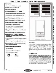
The <strong>MPC</strong>-<strong>6000</strong> is a modular fire alarm control unit. It features advanced addressable<br />
detection, programming, and memory capability. Its base configuration includes a power<br />
supply, an X1 addressable device circuit, four/two notification circuits (NAC), serial interface<br />
circuit, four status relays and a programming port.<br />
The <strong>MPC</strong>-<strong>6000</strong> control unit mounts in a 22" x 18" backbox with overall cover size of 22-9/32" x<br />
18-3/8". Operating controls and indicators are mounted on the inside hinged plate. An 80<br />
(4x20) – alphanumeric character LCD provides specific indications for addressable devices<br />
while LEDs indicate general panel status.<br />
Semi-flush mounting kits are available for the enclosure.<br />
The main board mounts in the rear of the enclosure. The power supply is physically contiguous<br />
with the main board. The <strong>MPC</strong>-<strong>6000</strong> main board (<strong>MPC</strong>6-MB or <strong>MPC</strong>6-MB2) provides the<br />
connections for external field wiring. Optional boards mount on the main board or on the rear<br />
of the enclosure.<br />
The display board (<strong>MPC</strong>6-DB or <strong>MPC</strong>6-DB2) mounts on the inner-hinged plate.<br />
All normal operation is controlled via a membrane keypad. Displays are provided by an 80-<br />
character, alphanumeric, backlit LCD display and by discrete LED indicators for major control<br />
unit functions.<br />
The 80-character (20 x 4) LCD is used to display event data, including alarms and troubles,<br />
identification of zone or device, and presentation of history. The display is controlled by a set of<br />
four push-button switches commanding the control processor. A back light is included in the<br />
display to assure visibility in low light, but to conserve power it is only activated during a<br />
reported event or on operation of a display control switch.<br />
Individual LEDs on the panel are provided to indicate SYSTEM ALARM, PREALARM,<br />
SUPERVISORY, ALARM SILENCED, SYSTEM TROUBLE and AC POWER ON. Direct pushbutton<br />
controls are provided for ALARM SILENCE, ACKNOWLEDGE, MENU and SYSTEM<br />
RESET. For <strong>MPC</strong>-<strong>6000</strong> Electronics Package2, LEDs for Releasing application<br />
(PREDISCHARGE, ABORT, DISCHARGE) are also provided.<br />
Power Supply<br />
A 24V (nominal) power supply provides all operating power to the control unit for both standby<br />
and alarm conditions. Sufficient battery charging capability is available to charge 38 AH sealed<br />
lead-acid batteries within code requirements for up to 90 hours quiescent plus 5 minutes<br />
alarm. The cabinet will hold batteries only up to 12 AH. The back-up battery is 24V, maintained<br />
by floating on the power supply. The battery will be automatically disconnected at low battery<br />
voltage to prevent deep discharge.<br />
X1 Addressable Device Circuit<br />
The <strong>MPC</strong>-<strong>6000</strong> control unit has one addressable device circuit utilizing the X1 Detection<br />
Technology. The circuit has the capacity for 252 addresses.<br />
4
<strong>MPC</strong>-<strong>6000</strong> / <strong>MPC</strong>-<strong>7000</strong> / <strong>RND</strong>-2 INSTALLATION, OPERATION AND MAINTENANCE MANUAL<br />
Notification Appliance Circuits<br />
The <strong>MPC</strong>-<strong>6000</strong> control unit has four independent Class B (Style Y) notification appliance<br />
circuits (NACs). Pairs of NACs can be combined for Class A (Style Z) operation. This reduces<br />
the number of NACs to two. Each circuit can be selected to give continuous output or one of<br />
five sounding patterns. There is also a system coder capable of zone-coded operation. All of<br />
the NACs are power limited and support synchronization of listed devices via the <strong>Faraday</strong><br />
SYNC Protocol.<br />
Serial Interface Circuit<br />
The <strong>MPC</strong>-<strong>6000</strong> control unit has a Serial Interface Circuit that will drive up to 16 remote LCD<br />
annunciators and up to a total of 8 Serial Relay Units and Serial Annunciator Units.<br />
Status Relays<br />
Four relays with dry contacts are provided. Three relays are programmable and the Trouble<br />
status relay is non-programmable. The relay contacts are Form C and are rated for 1A @<br />
28VDC resistive.<br />
Programming Port<br />
An RJ-11 jack is provided for a non-isolated RS-232 connection for temporary connection to a<br />
computer for panel programming.<br />
5
<strong>MPC</strong>-<strong>6000</strong> / <strong>MPC</strong>-<strong>7000</strong> / <strong>RND</strong>-2 INSTALLATION, OPERATION AND MAINTENANCE MANUAL<br />
<strong>MPC</strong>-<strong>7000</strong> SYSTEM DESCRIPTION<br />
The <strong>MPC</strong>-<strong>7000</strong> is an expandable modular fire alarm control unit. It features advanced<br />
addressable detection, programming, and memory capability. Its base configuration includes a<br />
power supply, two X1 addressable device circuits, four/two notification circuits (NAC), serial<br />
interface circuit, four status relays and a programming port.<br />
The basic <strong>MPC</strong>-<strong>7000</strong> control unit mounts in a 38" x 18" backbox with overall cover size of<br />
38-9/32" x 18-3/8". Operating controls and indicators are mounted on the inside hinged plate.<br />
An 80-character LCD provides specific indications for addressable devices while LEDs indicate<br />
general panel status.<br />
Semi-flush mounting kits are available for the enclosure.<br />
The main board mounts in the rear of the enclosure. The power supply is physically contiguous<br />
with the main board. The <strong>MPC</strong>-<strong>7000</strong> main board (<strong>MPC</strong>7-MB) provides the connections for<br />
external field wiring and connection points for optional modules. Optional boards mount on the<br />
main board or mount on the rear of the enclosure.<br />
The display board (<strong>MPC</strong>7-DB or <strong>MPC</strong>6-DB2) and controls mount on the inner-hinged plate.<br />
All normal operation is controlled from the front of the control unit via push-button switches.<br />
Displays are provided by an 80-character, alphanumeric, backlit LCD display and by discrete<br />
LED indicators for major control unit functions.<br />
The 80-character (20 x 4) LCD is used to display event data, including alarms and troubles,<br />
identification of zone or device, and presentation of history. The display is controlled by a set of<br />
four push-button switches commanding the control processor. A backlight is included in the<br />
display to assure visibility in low light, but to conserve power it is only activated during a<br />
reported event or on operation of a display control switch.<br />
Individual LEDs on the panel are provided to indicate SYSTEM ALARM, PREALARM,<br />
SUPERVISORY, ALARM SILENCED, SYSTEM TROUBLE and AC POWER ON. Direct pushbutton<br />
controls are provided for ALARM SILENCE, ACKNOWLEDGE, MENU and SYSTEM<br />
RESET.<br />
Power Supply<br />
A 24V (nominal) power supply provides all operating power to the control unit for both standby<br />
and alarm conditions. Sufficient battery charging capability is available to charge 38 AH sealed<br />
lead-acid batteries within code requirements for up to 60 hour quiescent plus 5 minutes alarm.<br />
The cabinet will hold batteries only up to 18 AH. The back-up battery is 24V, maintained by<br />
floating on the power supply. The battery will be automatically disconnected at low battery<br />
voltage to prevent deep discharge.<br />
X1 Addressable Device Circuits<br />
The <strong>MPC</strong>-<strong>7000</strong> control unit has two addressable device circuits (expandable to three or four),<br />
utilizing the X1 Detection Technology. Each circuit has the capacity for 252 addresses.<br />
6
<strong>MPC</strong>-<strong>6000</strong> / <strong>MPC</strong>-<strong>7000</strong> / <strong>RND</strong>-2 INSTALLATION, OPERATION AND MAINTENANCE MANUAL<br />
Notification Appliance Circuits<br />
The <strong>MPC</strong>-<strong>7000</strong> control unit has four (expandable to twelve) independent Class B (Style Y)<br />
notification appliance circuits (NACs). Pairs of NACs can be combined for Class A (Style Z)<br />
operation. This reduces the number of NACs to two (six). Each circuit can be selected to give<br />
continuous output or one of five sounding patterns. There is also a system coder capable of<br />
zone-coded operation. All of the NACs are power limited and support synchronization of listed<br />
devices via the <strong>Faraday</strong> SYNC Protocol.<br />
Serial Interface Circuit<br />
The <strong>MPC</strong>-<strong>7000</strong> control unit has a Serial Interface Circuit that will drive up to 16 remote LCD<br />
annunciators and up to a total of 8 Serial Relay Units and Serial Annunciator Units.<br />
Status Relays<br />
Four relays with dry contacts are provided. Three relays are programmable and the Trouble<br />
status relay is non-programmable. The relay contacts are Form C and are rated for 1A @<br />
28VDC resistive.<br />
Programming Port<br />
An RJ-11 jack is provided for a non-isolated RS-232 connection for temporary connection to a<br />
computer for panel programming.<br />
7
<strong>MPC</strong>-<strong>6000</strong> / <strong>MPC</strong>-<strong>7000</strong> / <strong>RND</strong>-2 INSTALLATION, OPERATION AND MAINTENANCE MANUAL<br />
<strong>RND</strong>-2 SYSTEM DESCRIPTION<br />
The <strong>RND</strong>-2 is a Remote Network Display designed to connect to a <strong>Faraday</strong> <strong>MPC</strong>-NET2<br />
Network. It features advanced programming and memory capability. Its base configuration<br />
includes a power supply, serial interface circuit, four status relays and a programming port.<br />
In a system with multiple panels connected via the <strong>MPC</strong>-NET2, the <strong>RND</strong> is used to<br />
Acknowledge, Silence and Reset the total system.<br />
The <strong>RND</strong>-2 Network annunciator mounts in a 22" x 18" backbox with overall cover size of<br />
22-9/32" x 18-3/8". Operating controls and indicators are mounted on the inside hinged plate.<br />
An 80 (20 x 4) – alphanumeric character LCD provides specific indications for addressable<br />
devices while LEDs indicate general panel status.<br />
Semi-flush mounting kits are available for the enclosure.<br />
The main board mounts in the rear of the enclosure. The power supply is physically contiguous<br />
with the main board. The <strong>RND</strong>-2 main board (<strong>MPC</strong>6-MB or <strong>MPC</strong>6-MB2) provides the<br />
connections for external field wiring. Optional boards mount on the main board and the<br />
network interface card mounts on the rear of the enclosure.<br />
The display board mounts on the inner-hinged plate.<br />
All normal operation is controlled via a membrane keypad. Displays are provided by an 80-<br />
character, alphanumeric, backlit LCD and by discrete LED indicators for major control unit<br />
functions.<br />
The 80-character LCD is used to display event data, including alarms and troubles,<br />
identification of network links or devices and presentation of history. The display is controlled<br />
by a set of four push-button switches commanding the control processor. A back light is<br />
included in the display to assure visibility in low light, but to conserve power it is only activated<br />
during a reported event or on operation of a display control switch.<br />
Individual LEDs on the panel are provided to indicate SYSTEM ALARM, PREALARM,<br />
SUPERVISORY, ALARM SILENCED, SYSTEM TROUBLE and AC POWER ON. Direct pushbutton<br />
controls are provided for ALARM SILENCE, ACKNOWLEDGE, MENU and SYSTEM<br />
RESET.<br />
Power Supply<br />
A 24V (nominal) power supply provides all operating power to the control unit for both standby<br />
and alarm conditions. Sufficient battery charging capability is available to charge 38 AH sealed<br />
lead-acid batteries within code requirements for up to 60 hour quiescent plus 5 minutes alarm.<br />
The cabinet will hold batteries only up to 12 AH. The back-up battery is 24V, maintained by<br />
floating on the power supply. The battery will be automatically disconnected at low battery<br />
voltage to prevent deep discharge.<br />
8
<strong>MPC</strong>-<strong>6000</strong> / <strong>MPC</strong>-<strong>7000</strong> / <strong>RND</strong>-2 INSTALLATION, OPERATION AND MAINTENANCE MANUAL<br />
Serial Interface Circuit<br />
The <strong>RND</strong>-2 control unit has a Serial Interface Circuit that will drive up to 16 remote LCD<br />
annunciators.<br />
Status Relays<br />
Four relays with dry contacts are provided. Three relays are programmable and the Trouble<br />
status relay is non-programmable. The relay contacts are Form C and are rated for 1A @<br />
28VDC resistive.<br />
Programming Port<br />
An RJ-11 jack is provided for a non-isolated RS-232 connection for temporary connection to a<br />
computer for panel programming.<br />
Refer to the <strong>MPC</strong>-NET2 Owner’s Manual, P/N 315-049594, for more details on the networking<br />
system.<br />
9
<strong>MPC</strong>-<strong>6000</strong> / <strong>MPC</strong>-<strong>7000</strong> / <strong>RND</strong>-2 INSTALLATION, OPERATION AND MAINTENANCE MANUAL<br />
OPTIONAL MODULES<br />
CT-1K City Tie Board (<strong>MPC</strong>-<strong>6000</strong> / <strong>MPC</strong>-<strong>7000</strong> / <strong>RND</strong>-2)<br />
The <strong>Faraday</strong> CT-1K city tie board provides local energy and polarity reversal connections. The<br />
polarity reversal connections provide a trouble circuit and an alarm circuit with optional trouble<br />
output. The CT-1K mounts on the <strong>MPC</strong>6-MB, <strong>MPC</strong>6-MB2 or <strong>MPC</strong>7-MB (Cannot be used in<br />
conjunction with a DACT Board).<br />
<strong>MPC</strong>-DACT Board (<strong>MPC</strong>-<strong>6000</strong> / <strong>MPC</strong>-<strong>7000</strong> / <strong>RND</strong>-2)<br />
The <strong>Faraday</strong> <strong>MPC</strong>-DACT Digital Alarm Communication Transmitter board will send control unit<br />
status data to a remote receiving station. The <strong>MPC</strong>-DACT mounts the <strong>MPC</strong>6-MB, <strong>MPC</strong>6-MB2<br />
or <strong>MPC</strong>7-MB (Cannot be used in conjunction with the City Tie Board).<br />
NPE-1 Transformer Assembly (<strong>MPC</strong>-<strong>6000</strong> / <strong>MPC</strong>-<strong>7000</strong>)<br />
The <strong>Faraday</strong> NPE-1 optional transformer assembly provides an additional 3 amps of NAC<br />
power. The transformer mounts in the cabinet above the two transformers that come standard<br />
with the <strong>MPC</strong>-<strong>6000</strong> / <strong>MPC</strong>-<strong>7000</strong>. A maximum of one optional NPE-1 is allowed per system.<br />
NEM-1 NAC Expansion Board (<strong>MPC</strong>-<strong>7000</strong>)<br />
The NEM-1 NAC Expansion Board has eight independent Class B (Style Y) notification<br />
appliance circuits (NACs). Pairs of NACs can be combined for Class A (Style Z) operation.<br />
This reduces the number of NACs to four. Each circuit can be selected to give continuous<br />
output or one of five sounding patterns. There is also a system coder capable of zone-coded<br />
operation.<br />
All of the NACs are power limited and support synchronization of listed devices via the<br />
<strong>Faraday</strong> SYNC Protocol. If a NEM-1 is installed in an <strong>MPC</strong>-<strong>7000</strong> panel, its NACs are<br />
synchronized in sets of 4 as follows:<br />
• NAC1, NAC2, NAC3 and NAC4 are synchronized with each other.<br />
• NAC5, NAC6, NAC7 and NAC8 are synchronized with each other.<br />
• NAC9, NAC10, NAC11 and NAC12 are synchronized with each other.<br />
A maximum of one NEM-1 NAC Expander board can be installed per <strong>MPC</strong>-<strong>7000</strong> panel.<br />
LEM-1 Loop Expander Board (<strong>MPC</strong>-<strong>7000</strong>)<br />
The LEM-1 has circuitry for the addition of an additional two FDLC Loop Driver boards to a<br />
<strong>MPC</strong>-<strong>7000</strong> panel. (FDLC Loop Driver Boards are not included). A maximum of one Loop<br />
Expander Board is allowed per <strong>MPC</strong>-<strong>7000</strong> system.<br />
FDLC Loop Driver Board (<strong>MPC</strong>-<strong>7000</strong>)<br />
The FDLC has one addressable device circuit that is programmed for connection to <strong>Faraday</strong><br />
addressable devices using the X1. The circuit has the capacity for 252 addresses. A maximum<br />
of four FDLC boards per <strong>MPC</strong>-<strong>7000</strong> panel is allowed. (Loops 3 and 4 require a LEM-1 Loop<br />
Expander Board.)<br />
HBC-1 Battery Charger (<strong>MPC</strong>-<strong>7000</strong>)<br />
The HBC-1 is an optional battery charger to increase the charging capacity of the <strong>MPC</strong>-<strong>7000</strong><br />
up to 100AH lead acid batteries.<br />
10
<strong>MPC</strong>-<strong>6000</strong> / <strong>MPC</strong>-<strong>7000</strong> / <strong>RND</strong>-2 INSTALLATION, OPERATION AND MAINTENANCE MANUAL<br />
Battery Sets<br />
The <strong>MPC</strong>-<strong>6000</strong> / <strong>MPC</strong>-<strong>7000</strong> / <strong>RND</strong>-2 control units are designed to use only rechargeable<br />
sealed lead-acid batteries for back-up power. Attaching a close-coupled battery box, if<br />
required, may allow use of battery sets beyond the physical capacity of the enclosure (12 AH<br />
for the <strong>MPC</strong>-<strong>6000</strong> and 18 AH for the <strong>MPC</strong>-<strong>7000</strong>). Maximum battery charging capacity for the<br />
<strong>MPC</strong>-<strong>6000</strong> is 38 AH. Maximum battery charging capacity for the <strong>MPC</strong>-<strong>7000</strong> is 38 AH. Some of<br />
the battery models are listed in the table below:<br />
Model Number Description Part Number Panel<br />
BT-34 10 Amp-Hour Battery Set 175-387140 <strong>MPC</strong>-<strong>6000</strong>/-<strong>7000</strong>/<strong>RND</strong>-2<br />
BP-61 15 Amp-Hour Battery Set 175-387194 <strong>MPC</strong>-<strong>6000</strong>/-<strong>7000</strong>/<strong>RND</strong>-2<br />
BTX-1 31 Amp-Hour Battery Set 175-083897 <strong>MPC</strong>-<strong>6000</strong>/-<strong>7000</strong>/<strong>RND</strong>-2<br />
BTX-2 55 Amp-Hour Battery Set 175-083898 <strong>MPC</strong>-<strong>7000</strong> with HBC-1<br />
BTX-3 100 Amp-Hour Battery Set 599-034220 <strong>MPC</strong>-<strong>7000</strong> with HBC-1<br />
<strong>MPC</strong>-REL Releasing Module (<strong>MPC</strong>-<strong>6000</strong> Only)<br />
The <strong>MPC</strong>-REL Releasing module is an optional accessory for the <strong>MPC</strong> <strong>6000</strong> Fire Alarm<br />
System Control Panel that allows the panel to control Sprinkler Systems (Pre-Action / Deluge),<br />
Water Spray Systems and Clean Agent Fire Suppression Systems via approved solenoids<br />
(NFPA 13, NFPA 750 and NFPA 2001). The <strong>MPC</strong>-REL provides two independent releasing<br />
circuits with a capacity of 1.5 amps each. This module is controlled by the panel. All of the<br />
operating parameters are programmed through the panel or the CIS-4 configuration tool. The<br />
<strong>MPC</strong>-REL requires an <strong>MPC</strong>-<strong>6000</strong> Electronics Package 2, see page 30, and an RPT-1<br />
transformer that mounts above the NPE-1 transformer(s).<br />
When an RPT-1 transformer is used, the optional NPE-1 transformer is not available.<br />
The <strong>MPC</strong>-REL must not be installed in a networked system.<br />
12603A (<strong>MPC</strong>-<strong>6000</strong> / <strong>MPC</strong>-<strong>7000</strong> / <strong>RND</strong>-2)<br />
This is the basic NIB (Network Interface Board) card that is installed in the panel enclosure that<br />
allows the panel to communicate in the <strong>MPC</strong>-NET2 network. It is connected to the serial port of<br />
the main board (<strong>MPC</strong>6-MB, <strong>MPC</strong>6-MB2, <strong>MPC</strong>7-MB2). Refer to the <strong>MPC</strong>-NET2 Owner’s<br />
Manual, P/N 315-049594, for more information.<br />
12523A (<strong>MPC</strong>-<strong>6000</strong> / <strong>MPC</strong>-<strong>7000</strong> / <strong>RND</strong>-2)<br />
The 12523A is a 12603A NIB (Network Interface Board) card installed in a 12411 surface box<br />
enclosure that is installed external to the panel enclosure. It is connected to the serial port of<br />
the main board (<strong>MPC</strong>6-MB, <strong>MPC</strong>6-MB2, <strong>MPC</strong>7-MB2). Refer to the <strong>MPC</strong>-NET2 Owner’s<br />
Manual, P/N 315-049594, for more information.<br />
11
<strong>MPC</strong>-<strong>6000</strong> / <strong>MPC</strong>-<strong>7000</strong> / <strong>RND</strong>-2 INSTALLATION, OPERATION AND MAINTENANCE MANUAL<br />
12526A (<strong>MPC</strong>-<strong>6000</strong> / <strong>MPC</strong>-<strong>7000</strong> / <strong>RND</strong>-2)<br />
The 12526A is a 12523A NIB (Network Interface Board) card has an RS232 daughter card.<br />
This allows the network to be connected to a diagnostics isolated serial printer to print network<br />
events. Refer to the <strong>MPC</strong>-NET2 Owner’s Manual, P/N 315-049594, for more information.<br />
12525 (<strong>MPC</strong>-<strong>6000</strong> / <strong>MPC</strong>-<strong>7000</strong> / <strong>RND</strong>-2)<br />
This is a line surge suppressor module that allows the NIB cards to be installed in a separate<br />
building location. This module is installed in a 12525 surface box enclosure that is installed<br />
external to the panel. Refer to the <strong>MPC</strong>-NET2 Owner’s Manual, P/N 315-049594, for more<br />
information.<br />
12535 (<strong>MPC</strong>-<strong>6000</strong> / <strong>MPC</strong>-<strong>7000</strong> / <strong>RND</strong>-2)<br />
This is a multi-mode fiber optic converter that is installed in NIB cards. Refer to the <strong>MPC</strong>-NET2<br />
Owner’s Manual, P/N 315-049594, for more information.<br />
12536 (<strong>MPC</strong>-<strong>6000</strong> / <strong>MPC</strong>-<strong>7000</strong> / <strong>RND</strong>-2)<br />
This is a single-mode fiber optic converter that is installed in NIB cards. Refer to the <strong>MPC</strong>-<br />
NET2 Owner’s Manual, P/N 315-049594, for more information.<br />
12
<strong>MPC</strong>-<strong>6000</strong> / <strong>MPC</strong>-<strong>7000</strong> / <strong>RND</strong>-2 INSTALLATION, OPERATION AND MAINTENANCE MANUAL<br />
AUXILIARY MODULES<br />
Serial LCD Annunciators<br />
The RDC-2 Serial LCD Annunciator consists of a backlit 80 character (20 x 4) alphanumeric<br />
LCD display, 4 menu buttons, 4 dedicated buttons for operator interface, 6 LED indicators and<br />
a security key switch. The display and controls of the RDC-2 are the same as those on the<br />
front of the <strong>MPC</strong>-<strong>7000</strong> and <strong>RND</strong>-2 panels, including a key switch for security. The backlight<br />
activates only during active button press or when events are present in the system to conserve<br />
power. The RDC-2 can be installed in <strong>RND</strong>-2 and <strong>MPC</strong>-<strong>7000</strong> panels. It can also be installed in<br />
the <strong>MPC</strong>-<strong>6000</strong> panel provided that the Releasing application features are not used.<br />
The RDC-3 Serial LCD annunciator consists of a backlit 80 character (20 x 4) alphanumeric<br />
LDC display, 4 menu buttons, 4 dedicated buttons for operator interface, 9 LED indicators and<br />
a security key switch. The display and controls of the RDC-3 are the same as those on the<br />
front of the <strong>MPC</strong>-<strong>6000</strong> panel including a key switch for security. The backlight activates only<br />
during active button press or when events are present on the system to conserve power. The<br />
RDC-3 can be installed in <strong>MPC</strong>-<strong>6000</strong> panels with releasing application only.<br />
Up to sixteen annunciators may be addressed by the communication circuit. Some may require<br />
additional RSE-300 auxiliary power supplies depending on the total accessory power loading.<br />
Serial Relay Unit and Serial Relay Extender<br />
The SRU-2 Serial Relay Unit includes a processor board and a relay board. The processor board<br />
receives commands from the control unit for activating the relays and transmits supervision<br />
and control functions to the control unit. The processor board can control up to 3 SRE-8 relay<br />
boards. Each relay board provides 8 programmable relays with Form C contacts. The control<br />
unit can address up to a total of 8 Serial Relay Units and/or Serial Annunciator Units. RSE-300<br />
auxiliary power supplies will be required to power units beyond the control unit capability.<br />
Serial Annunciator Unit and Serial Annunciator Extender<br />
The SLU-2 Serial Annunciator Unit includes a processor board and an annunciator driver<br />
board. The processor board receives commands from the control unit for activating the outputs<br />
and transmits supervision and control functions to the control unit. The processor board can<br />
control up to 4 SLE-16 annunciator driver boards. Each driver board provides 16 supervised<br />
programmable outputs for LEDs or incandescent lamps. The control unit can address up to 8<br />
Serial Relay Units and/or Serial Annunciator Units. RSE-300 auxiliary power supplies will be<br />
required to power units beyond the control unit capability.<br />
RSE-300 Remote Signal Expander<br />
The RSE-300 is a notification appliance circuit expander with a built-in auxiliary power output.<br />
This power source is designed to provide power for notification appliances, door holders and<br />
4-wire smoke detectors. The RSE-300 provides 6 amps of 24 VDC power for multiple uses. All<br />
6 amps can be directed to 4 Notification Appliance Circuits (NACs). Each is rated at 3 amps<br />
and is power limited. Either 1 or 2 inputs can control the four outputs. These outputs are<br />
compatible with <strong>Faraday</strong> notification appliances.<br />
The RSE-300 can be configured so that the inputs can be programmed to provide steady<br />
outputs, ANSI temporal outputs, or <strong>Faraday</strong> SYNC protocol for synchronized horn/strobe<br />
outputs. It can also be programmed to silence <strong>Faraday</strong> sync horns while the sync strobes<br />
remain on, using two wires. This requires a silenceable and non-silenceable input.<br />
The RSE-300 also offers a 3 amp auxiliary output for driving other portions of your fire alarm system.<br />
13
<strong>MPC</strong>-<strong>6000</strong> / <strong>MPC</strong>-<strong>7000</strong> / <strong>RND</strong>-2 INSTALLATION, OPERATION AND MAINTENANCE MANUAL<br />
X1 ADDRESSABLE DEVICES<br />
Fire Smart Smoke Detector<br />
The control unit processor sends the sensitivity and pre-alarm settings to the detectors and<br />
polls the detectors as to their status. The detector determines normal, trouble, pre-alarm or<br />
alarm conditions and communicates the status to the control unit.<br />
Variable Thesholds - The detectors can be set to operate in various pre-programmed<br />
optimizations, depending on installation locations.<br />
Operator Alerts - The control unit can trigger an alarm or trouble automatically on the<br />
occurrence of a number of conditions of the detector. These include (but are not limited to):<br />
Maintenance alert<br />
Pre-alarm alert<br />
No response<br />
Incorrect response<br />
Multiple response<br />
Heat Detectors<br />
Addressable heat sensing detectors may be intermixed on the circuit for locations where heat<br />
sensing may be the most effective detection mode. The heat detectors may be programmed<br />
for rate of rise operation.<br />
Addressable Modules (Monitor and Control)<br />
In addition to detectors, the circuit can communicate with addressable modules, allowing<br />
initiating devices or notification appliances with local power sources to supervise the power<br />
sources and generate event conditions.<br />
Manual Stations<br />
Addressable manual stations may be intermixed on the circuit with proper response<br />
programmed into the control unit.<br />
Programming X1 Devices<br />
X1 devices can be programmed in the following manner:<br />
8720 Device Programmer/ Loop Tester - Refer to the 8720 User’s Manual, P/N 315-<br />
033260FA, for further information.<br />
<strong>MPC</strong>-<strong>6000</strong> / <strong>MPC</strong>-<strong>7000</strong> / <strong>RND</strong>-2 Panel Keypad – Refer to the <strong>MPC</strong>-<strong>6000</strong> / <strong>MPC</strong>-<strong>7000</strong> /<br />
<strong>RND</strong>-2 Programmer’s Manual, P/N 315-049403FA, for detailed information of system<br />
programming. Used only for field removal and reinstallation of individual devices.<br />
14
<strong>MPC</strong>-<strong>6000</strong> / <strong>MPC</strong>-<strong>7000</strong> / <strong>RND</strong>-2 INSTALLATION, OPERATION AND MAINTENANCE MANUAL<br />
EVENT HISTORY<br />
The control unit includes a non-volatile memory recording over 1900 system events. Identified<br />
alarm, trouble, supervisory trouble and other significant events will be recorded along with the<br />
date and time of occurrence and can be inspected by operating front panel push buttons.<br />
Events recorded in the history are:<br />
Alarm, Trouble or Supervisory conditions.<br />
Drill, Recall and General Evacuation.<br />
Activation of NACs or modules used for sounders or strobes.<br />
Unit used for command functions (Silence, acknowledge, reset, etc.).<br />
Alarm silence (Manual).<br />
System reset.<br />
Power up.<br />
Entry to Programmer Mode.<br />
Back-up configuration edited.<br />
Validity check on backup configuration (Errors detected or no errors detected).<br />
Replacement of primary configuration.<br />
Execution of Auto-program.<br />
Exit from Programmer Mode.<br />
System time or date change.<br />
Input point disable/enable.<br />
Start and stop of Quick Test.<br />
Expiration of Quick Test Timer.<br />
Trouble/supervisory reminder.<br />
Alarm/trouble/supervisory Acknowledgment.<br />
Trouble/supervisory restored to normal.<br />
Pre-alarm activation.<br />
Pre-alarm acknowledgment/restore.<br />
Activation of points defined for logging.<br />
Pre-discharge condition (Applicable to <strong>MPC</strong>-<strong>6000</strong> with Releasing application only).<br />
Discharge condition (Applicable to <strong>MPC</strong>-<strong>6000</strong> with Releasing application only).<br />
Abort condition (Applicable to <strong>MPC</strong>-<strong>6000</strong> with Releasing application only).<br />
Manual Fan Restart.<br />
15
<strong>MPC</strong>-<strong>6000</strong> / <strong>MPC</strong>-<strong>7000</strong> / <strong>RND</strong>-2 INSTALLATION, OPERATION AND MAINTENANCE MANUAL<br />
GENERAL DESIGN FEATURES<br />
Environmental<br />
The <strong>MPC</strong>-<strong>6000</strong>/<strong>MPC</strong>-<strong>7000</strong>/<strong>RND</strong>-2 panels and subassemblies are suitable for use in a dry,<br />
interior or protected location.<br />
Power Limiting<br />
The AC power, battery wiring and open collector circuits (when <strong>MPC</strong>-REL is installed) are not<br />
power limited. All other circuits leaving the control unit are power limited, provided the proper<br />
installation rules are maintained.<br />
Ground Fault Detection<br />
The control unit provides system ground fault detection and is annunciated as a trouble<br />
condition on the system. In addition, each addressable loop circuit has its own ground<br />
detection circuitry and indicator.<br />
System (+) Ground Fault Threshold
<strong>MPC</strong>-<strong>6000</strong> / <strong>MPC</strong>-<strong>7000</strong> / <strong>RND</strong>-2 INSTALLATION, OPERATION AND MAINTENANCE MANUAL<br />
Device address supervision: The system checks that all configured devices on the addressable<br />
device circuit and the Serial Interface Circuit respond to an address poll. The system reports a<br />
trouble condition if the following conditions are detected:<br />
• Configured device is missing.<br />
• Unconfigured device is installed.<br />
• Two devices are programmed with the same address location.<br />
• Loop card is shorted.<br />
When “loop card is shorted,” trouble is detected by the panel; all devices on the loop card are<br />
disabled and will not be able to annunciate any events.<br />
REGULATORY STANDARDS<br />
The <strong>MPC</strong>-<strong>6000</strong> / <strong>MPC</strong>-<strong>7000</strong> control units and the <strong>RND</strong>-2 network annunciator meet the<br />
requirements of industry and government regulatory agencies as noted.<br />
Federal Communications Commission<br />
The <strong>MPC</strong>-DACT meets the Class A requirements of the Code of Federal Regulations (CFR<br />
47), Part 15, for electromagnetic field emissions. The <strong>MPC</strong>-DACT also meets the requirements<br />
of the Code of Federal Regulations (CFR 47), Part 68, for connection of equipment to the<br />
public switched telephone network.<br />
Underwriters Laboratories<br />
The <strong>MPC</strong>-<strong>6000</strong> / <strong>MPC</strong>-<strong>7000</strong> Fire Alarm control units and the <strong>RND</strong>-2 network annunciator are<br />
listed under UL Standard 864 for compliance to NFPA Standard 72 for fire service.<br />
17
<strong>MPC</strong>-<strong>6000</strong> / <strong>MPC</strong>-<strong>7000</strong> / <strong>RND</strong>-2 INSTALLATION, OPERATION AND MAINTENANCE MANUAL<br />
GENERAL SPECIFICATIONS<br />
Operating specifications for the <strong>MPC</strong>-<strong>6000</strong> / <strong>MPC</strong>-<strong>7000</strong> / <strong>RND</strong>-2 are as follows:<br />
Environmental<br />
Operating temperature - 32 - 120F (0 - 49C)<br />
Relative humidity - Up to 93% @ 90F (32C)<br />
To be installed in a dry protected environment only<br />
Primary Supply<br />
Primary Input Voltage: 120 VAC (60 Hz) nominal<br />
<strong>MPC</strong>-<strong>6000</strong> / <strong>RND</strong>-2 Maximum primary input current: 2.4A at 120 VAC<br />
<strong>MPC</strong>-<strong>7000</strong> Maximum primary input current: 3.5A at 120 VAC<br />
Secondary Power Supply<br />
24 volt lead-acid battery set<br />
Maximum Charge Voltage: 27.8 VDC<br />
Automatic Low Battery Disconnect - Disconnect Voltage: 18VDC<br />
<strong>MPC</strong>-<strong>6000</strong> / <strong>RND</strong>-2 Maximum Charge Current: 1.7A (Minimum supervisory load)<br />
<strong>MPC</strong>-<strong>7000</strong> Maximum Charge Current: 3.8A<br />
<strong>MPC</strong>-<strong>6000</strong> / <strong>RND</strong>-2 Battery capacity: 7-38 AH (over 12 AH requires separate enclosure for<br />
the batteries)<br />
<strong>MPC</strong>-<strong>7000</strong> Battery capacity: 7-38 AH / 100 AH with optional Battery Charger, HBC-1 (over<br />
18 AH requires separate enclosure for the batteries)<br />
Auxiliary Power Outputs<br />
0.4A maximum per power output circuit<br />
Non-Resettable Power Output<br />
Power limited<br />
Voltage: 24 VDC nominal (31 VDC max.) filtered<br />
Ripple: 1.5 VAC maximum (120Hz)<br />
Resettable Power Output<br />
Power limited<br />
Voltage: 24 VDC nominal (31 VDC max.) filtered<br />
Ripple: 1.5 VAC maximum (120Hz)<br />
The maximum cumulative available power output (including Auxiliary power and Serial<br />
Interface power) is: 0.5A for <strong>MPC</strong>-<strong>6000</strong>/<strong>RND</strong>-2, 1.0A for <strong>MPC</strong>-<strong>7000</strong>.<br />
Status Relays<br />
Three programmable relays<br />
One Non-programmable status relay<br />
Status: Trouble<br />
Contact Rating:<br />
1 A, 28 VDC maximum, resistive<br />
Form C Contact<br />
18
<strong>MPC</strong>-<strong>6000</strong> / <strong>MPC</strong>-<strong>7000</strong> / <strong>RND</strong>-2 INSTALLATION, OPERATION AND MAINTENANCE MANUAL<br />
Notification Appliance Circuits<br />
Power limited<br />
Supervised<br />
Maximum Standby Current: 3.4mA<br />
Maximum Line Resistance @ 24V (nominal), unfiltered fullwave rectified<br />
Current Draw Line Impedance<br />
1.5A 2Ω<br />
1.0A 3Ω<br />
0.5A 6Ω<br />
Alarm Voltage: 24V, nominal (31V max.), unfiltered fullwave rectified<br />
Maximum Ripple: 16 VAC, 120Hz<br />
Use for special application only<br />
<strong>MPC</strong>-<strong>6000</strong> Four Style Z/Class B or two Style Y/Class A circuits<br />
<strong>MPC</strong>-<strong>7000</strong> Four Style Z/Class B or two Style Y/Class A circuits<br />
Expandable to twelve Style Z/Class B or six Style Y/Class A circuits<br />
Maximum NAC Current: 1.5A / NAC circuit<br />
<strong>MPC</strong>-<strong>6000</strong> maximum total NAC current 3.0A (6.0A with optional NPE-1 transformer installed)<br />
<strong>MPC</strong>-<strong>7000</strong> Maximum total NAC current 5.0A (8.0A with optional NPE-1 transformer installed)<br />
Suitable for coded and non-coded application<br />
Refer to Appendix B to determine maximum synchronized notification appliances allowed<br />
per NAC<br />
Serial Interface Circuit<br />
Power limited<br />
Supervised<br />
(+, -) Voltage: 24 VDC nominal (31 VDC max.) filtered<br />
Maximum current: 0.40A at 24VDC<br />
(X+, X-) RS485 Voltage levels<br />
Maximum wire loop resistance: 11 ohms/line<br />
Communications Protocol: RS485<br />
The maximum cumulative available power output (including Auxiliary power and Serial<br />
Interface power) is: 0.5A for <strong>MPC</strong>-<strong>6000</strong>/<strong>RND</strong>-2, 1.0A for <strong>MPC</strong>-<strong>7000</strong>.<br />
X1 Addressable Device Circuits<br />
Power limited<br />
Supervised<br />
Voltage: 24 VDC nominal (31 VDC max.) filtered<br />
Maximum Current (shorted): 0.375A<br />
Maximum wire loop resistance: 50 ohms (see graph in Appendix A on page 60)<br />
Style 4 or 6 circuit<br />
252 Addresses: detectors and modules max.<br />
<strong>MPC</strong>-<strong>6000</strong>: One circuit<br />
<strong>RND</strong>-2: No loop circuits<br />
<strong>MPC</strong>-<strong>7000</strong>: Two circuits expandable to four<br />
19
<strong>MPC</strong>-<strong>6000</strong> / <strong>MPC</strong>-<strong>7000</strong> / <strong>RND</strong>-2 INSTALLATION, OPERATION AND MAINTENANCE MANUAL<br />
City Tie (Optional City Tie Board P/N CT-1K)<br />
CA<br />
Reverse Polarity: Selectable for Alarm with Trouble or Alarm only operation<br />
Not power limited<br />
Supervised by receiver<br />
Voltage: 24 VDC nominal (31 VDC max.) filtered<br />
Current: 0.020A maximum (normal or trouble)<br />
Current: 0.025A maximum (shorted)<br />
Ripple: 1.5 VAC maximum, 120Hz<br />
CT Reverse Polarity: Programmable for Trouble or Supervisory or both<br />
Not power limited<br />
Supervised by receiver<br />
Voltage: 24 VDC nominal (31 VDC max.) filtered<br />
Current: 0.020A maximum (normal or alarm)<br />
Current: 0.025A maximum (shorted)<br />
Ripple: 1.5 VAC maximum, 120Hz<br />
LE<br />
Local Energy<br />
Not power limited<br />
Supervised for open by control unit<br />
Voltage: 24 VDC nominal (31 VDC max.) filtered<br />
Standby Current: 0.007A maximum<br />
Alarm Current: 0.400A maximum<br />
Ripple: 1.5 VAC maximum, 120Hz<br />
Maximum wire loop resistance: 30 ohms<br />
Trip coil impedance: 14.5 ohms<br />
DACT Circuit (Optional DACT Board <strong>MPC</strong>-DACT)<br />
Power limited<br />
Supervised for short or open circuit<br />
Maximum Voltage: 60 VDC<br />
Maximum Current (shorted): 0.100A<br />
Additional Transformer (Optional Transformer Sub-assembly NPE-1)<br />
Provides an additional 3.0A of NAC power (max. 1 per panel)<br />
20
<strong>MPC</strong>-<strong>6000</strong> / <strong>MPC</strong>-<strong>7000</strong> / <strong>RND</strong>-2 INSTALLATION, OPERATION AND MAINTENANCE MANUAL<br />
<strong>MPC</strong>-REL (Optional Releasing Module for <strong>MPC</strong>-<strong>6000</strong> only)<br />
Two power limited releasing circuits<br />
Four non-power limited open collector circuits<br />
Releasing Circuits are rated at 1.5A at 24VDC, filtered<br />
Open Collector Circuits are rated at 200mA at 24VDC, filtered<br />
Maximum cumulative current output must not exceed 3A<br />
Each Releasing Circuit requires REL-EOL module (P/N 500-696359) installed as close as<br />
possible to the last solenoid for proper wire supervision<br />
Requires an RPT-1 transformer<br />
REL-EOL module (P/N 500-696359) is required for supervision of open and short circuits on<br />
the releasing circuit. REL-EOL must be in the same enclosure or close nippled to the last<br />
solenoid in the loop.<br />
21
<strong>MPC</strong>-<strong>6000</strong> / <strong>MPC</strong>-<strong>7000</strong> / <strong>RND</strong>-2 INSTALLATION, OPERATION AND MAINTENANCE MANUAL<br />
CONTROL UNIT OPERATION<br />
OPERATION INSTRUCTIONS<br />
Standby Condition<br />
In normal standby operation, the green AC POWER ON LED should be illuminated and no<br />
other indicator operating. The display will show the system label and the current date, day, and<br />
time.<br />
Alarm Conditions<br />
GENERAL ALARM<br />
When a general alarm occurs, all NACs with output type set to “ALARM” activate.<br />
To activate a general alarm, proceed as follows:<br />
Press "MENU".<br />
On the MENU display, select "GENERAL ALARM".<br />
At the next screen, select "Yes".<br />
Silence and reset the system to restore the system to supervisory state.<br />
NORMAL ALARM<br />
When the system detects an alarm condition, the system alarm LED activates (ON - flashing)<br />
and the buzzer activates (ON - steady). Local audible and visual signals along with remote<br />
alarm signals operate and the LCD panel indicates the alarm.<br />
On receipt of an alarm, proceed in accordance with the established emergency plan. Assure<br />
that all personnel are accounted for, and notify the Fire Department.<br />
To silence the audible after evacuation (where permitted by the codes and control unit<br />
programming), press ALARM SILENCE. The alarm audible will be silenced, the alarm silence<br />
LED will be illuminated.<br />
Operating the ACKNOWLEDGE button will silence the local buzzer and change the LED alarm<br />
indicator from flashing to steady.<br />
WATERFLOW Alarms<br />
Alarms detected on devices with usage designated as “waterflow” to indicate sprinkler<br />
operation and the audible alarms cannot be silenced in this condition. Operation of alarm<br />
silence will produce no effect.<br />
SILENCEABLE WATERFLOW Alarms<br />
Alarms detected on devices with usage designated as “waterflow” to indicate sprinkler<br />
operation. The associated audibles are silenceable.<br />
POSITIVE Alarm Sequence (PAS)<br />
Activation of an initiating device in an input group programmed for PAS, activates the Alarm<br />
LED, display, buzzer, system and user-programmed outputs, but delays additional<br />
programmed outputs for 15 seconds.<br />
22
<strong>MPC</strong>-<strong>6000</strong> / <strong>MPC</strong>-<strong>7000</strong> / <strong>RND</strong>-2 INSTALLATION, OPERATION AND MAINTENANCE MANUAL<br />
Operation of the ACKNOWLEDGE button within 15 seconds will add a number of seconds (60-<br />
180) to the PAS timer for the purpose of investigation. If the ACKNOWLEDGE button is not<br />
operated within 15 seconds, the additional user-programmed outputs activate.<br />
If the initiating device and the panel are reset before the PAS timer times out, the alarm<br />
sequence is aborted.<br />
During the investigation period, an alarm condition on a device programmed for direct alarm<br />
response will override the PAS timer and activate the additional user-programmed outputs.<br />
See the <strong>MPC</strong>-<strong>6000</strong> / <strong>MPC</strong>-<strong>7000</strong>/ <strong>RND</strong>-2 Programming Manual, P/N 315-049403FA, for<br />
additional details.<br />
PRE-SIGNAL ALARMS<br />
Activation of an initiating device in an input group programmed for PRE-SIGNAL, activates the<br />
Alarm LED, display, buzzer, system and user-programmed outputs.<br />
The delay of activation of additional user-programmed outputs can be programmed from 60 to<br />
180 seconds. If the system is not reset during this period, these additional user-programmed<br />
outputs will activate.<br />
See the <strong>MPC</strong>-<strong>6000</strong> / <strong>MPC</strong>-<strong>7000</strong>/ <strong>RND</strong>-2 Programming Manual, P/N 315-049403FA, for<br />
additional details.<br />
Do not reset the system until the alarm condition has been cleared. The LCD will indicate the<br />
area in which the alarm was detected. The detector or module associated with the device<br />
initiating the alarm will display a light indicating activation (if applicable).<br />
When the alarm condition has been corrected, return the system to standby operation by<br />
pressing the SYSTEM RESET button.<br />
ALARMS ON RELEASING ZONES (<strong>MPC</strong>-<strong>6000</strong> ONLY)<br />
Devices that activate the releasing circuits must be assigned to the releasing group via the CIS-4<br />
configuration tool or front panel programming. The releasing group may be configured to activate on<br />
any one alarm, any two alarms, or any one smoke plus any one thermal alarm.<br />
For instance, if the threshold of the group was set at any 2, the following would occur:<br />
The first device activating will put the panel in a releasing group 1 st alarm condition. When the 2 nd<br />
device in that group activates, it will start the pre-discharge timer and put the panel in the pre-discharge<br />
condition. If the threshold were to be set at one, any device in that group activating would immediately<br />
start the pre-discharge timer.<br />
When the pre-discharge timer is activated, the LCD displays the timer as it counts down and the “Pre-<br />
Discharge” LED will be ON-steady.<br />
When the pre-discharge timer expires, the panel goes to the discharge condition and activates the<br />
releasing zones. The “Discharge” LED will be ON-steady.<br />
It is recommended that the releasing group has devices with abort and manual release usages.<br />
23
<strong>MPC</strong>-<strong>6000</strong> / <strong>MPC</strong>-<strong>7000</strong> / <strong>RND</strong>-2 INSTALLATION, OPERATION AND MAINTENANCE MANUAL<br />
Abort Function<br />
Input modules may be assigned to the “Abort” usage. The abort type is selected when the releasing<br />
application is activated. Failure of the abort switch to communicate with the fire panel will automatically<br />
restart the agent release timer. When the abort input is activated, it puts the panel in abort condition<br />
and turns the “Abort” LED to ON-steady. The following abort functions may be assigned:<br />
ULI Standard UL Type Delay Timer<br />
If the abort function type is configured as ULI and an abort condition is initiated during pre-discharge<br />
condition, the pre-discharge delay timer counts down or restores to 10 seconds then holds as long as<br />
the abort switch is pressed. The pre-discharge delay timer will resume the countdown as soon as the<br />
abort switch is released.<br />
IRI Type Delay Timer<br />
If the abort function type is configured as IRI, an abort condition is initiated only if the abort switch is<br />
held during the releasing group 1 st alarm condition. Otherwise, it will be ignored. When the abort switch<br />
is held during the 1 st alarm condition, the pre-discharge timer is prevented from starting even if the<br />
threshold is subsequently met. When abort is released, pre-discharge starts from the beginning.<br />
A releasing threshold of “Any 1” is not allowed for an IRI abort type.<br />
NYC Type Delay Timer<br />
If the abort function type is configured as NYC, it meets the New York City abort condition requirement<br />
for releasing application. If the abort condition is initiated during the pre-discharge condition, a 90<br />
second investigation time delay is added before pre-discharge delay countdown initiates again.<br />
AHJ Local Jurisdiction Delay Timer<br />
If the abort timer function type is configured as AHJ and abort condition is initiated during pre-discharge<br />
condition, the pre-discharge delay timer is restored to its initial programmed value and will not start the<br />
countdown as long as the abort switch is pressed.<br />
A supervisory condition is initiated whenever the abort switch is pressed.<br />
Failure of an initiated abort switch to communicate with the fire panel will automatically restart the predischarge<br />
delay countdown timer.<br />
See the <strong>MPC</strong>-<strong>6000</strong> / <strong>MPC</strong>-<strong>7000</strong> / <strong>RND</strong>-2 Programming Manual, PN 315-049403FA for more information.<br />
Manual Release<br />
Input modules can be configured for “Manual Release” usage to be used for releasing application only.<br />
If an input module programmed for Manual Release is initiated, it will generate an alarm condition,<br />
override all abort timers and activated abort switches, and automatically activate the releasing circuits<br />
placing the panel in discharge condition. A manual release courtesy delay is provided if required.<br />
See the <strong>MPC</strong>-<strong>6000</strong> / <strong>MPC</strong>-<strong>7000</strong> / <strong>RND</strong>-2 Programming Manual, PN 315-049403FA for more information.<br />
Trouble Conditions<br />
In case of a trouble condition, the system trouble LED and any programmed trouble LEDs activate (ONpulsing),<br />
the LCD identifies the problem and the buzzer sounds (pulsing). Refer to the applicable<br />
section of the system manual to determine the probable cause of the trouble and the action to be taken.<br />
When the trouble condition has been noted, pressing the ACKNOWLEDGE button will silence the<br />
buzzer and change the trouble LED to steady ON. If the panel is configured for Supv/Trouble Resound<br />
Reminder and the trouble condition is not corrected and the Supv/Trouble Resound Reminder timer has<br />
elapsed, the panel will re-annunciate the trouble condition.<br />
24
<strong>MPC</strong>-<strong>6000</strong> / <strong>MPC</strong>-<strong>7000</strong> / <strong>RND</strong>-2 INSTALLATION, OPERATION AND MAINTENANCE MANUAL<br />
If the control unit is programmed for “trouble acknowledge required”, when the indicated trouble<br />
condition has been cleared, the system reverts to standby condition only after the ACKNOWLEDGE<br />
button is pressed.<br />
Some trouble conditions are latching troubles that require a system reset to restore the<br />
control unit to supervisory mode.<br />
Supervisory Conditions<br />
In case of a supervisory condition, the system supervisory LED activates (ON – flashing) and the<br />
sounder activates (ON – pulsing).<br />
When the supervisory has been noted, pressing the ACKNOWLEDGE button will silence the buzzer<br />
and change the supervisory LED to steady ON. If the panel is configured for Supv/Trouble Resound<br />
Reminder and the supervisory condition is not corrected and the Supv/Trouble Resound Reminder<br />
timer has elapsed, the panel will re-annunciate the supervisory condition.<br />
The releasing zone will indicate a supervisory condition when it is disabled.<br />
Detector Pre-Alarm Conditions<br />
A pre-alarm condition is annunciated by pre-alarm LEDs and buzzers on the control unit and LCD<br />
Annunciators and Remote Processors. The LEDs flash and buzzers are on steady until acknowledgment.<br />
Acknowledging the pre-alarm condition puts LEDs on steady and buzzers off.<br />
If pre-alarm has been acknowledged and the system restores to normal, the condition clears.<br />
Fan Restart<br />
If the fan restart feature is implemented, the input keyswitch (Independent Fan Restart procedure) with<br />
fan restart usage must be initiated to deactivate the hold-thru reset output. A supervisory condition will<br />
be annunciated that will clear when the keyswitch is restored to its standby state.<br />
Fan restart can also be initiated from the front panel—user level. If fan restart is initiated from the panel<br />
(Global Fan Restart procedure), all outputs with hold-thru reset output type will immediately deactivate.<br />
If a Global Fan Restart procedure is initiated, precaution must be taken to prevent physical<br />
damage to the fans, dampers, air ducts and other equipment. For example, staggering fan<br />
activation to avoid power surges and verifying that dampers are opened before the fan<br />
activates to prevent damage to the air ducts. These parameters must be monitored and<br />
controlled by another method/technique that is not discussed in this manual.<br />
Maintenance<br />
In order to ensure continued safe and reliable operation of the fire alarm system, periodic inspection<br />
and testing should be performed in accordance with applicable NFPA 72 standards.<br />
If the system has remote connections to the Fire Department or other monitor, be sure to<br />
disable the remote signals and/or notify the remote monitoring station before performing test<br />
operations.<br />
To access the Panel Firmware Version Number:<br />
Press Menu on the keypad<br />
Select the Maintenance mode<br />
Enter the maintenance password<br />
If password is correct, the firmware version displays on the LCD screen.<br />
For any required service, refer to the system manual or contact a factory authorized representative.<br />
25
<strong>MPC</strong>-<strong>6000</strong> / <strong>MPC</strong>-<strong>7000</strong> / <strong>RND</strong>-2 INSTALLATION, OPERATION AND MAINTENANCE MANUAL<br />
ADDITIONAL OPERATING PROCEDURES<br />
In addition to the basic fire alarm instructions above, several features are included to facilitate<br />
maintenance and increase the versatility of the system. Following are procedures to call up these<br />
functions.<br />
Lamp Test<br />
When selected, Lamp Test activates the buzzer and turns on all the LEDs on the user interface for 2<br />
seconds, then reverts to its previous state.<br />
To initiate a Lamp Test, proceed as follows:<br />
Press "MENU".<br />
On the MENU display, select "More".<br />
On the next screen, select "More" again.<br />
Select Lamp Test to initiate the lamp test sequence.<br />
Select “Esc” to return the control unit to normal display.<br />
Note that lamp test operates the indicators only on the units being operated and no record is reported<br />
to system history.<br />
Drill<br />
When selected, activates all NACs assigned to the Output Zone selected for “Drill”.<br />
To activate a fire alarm drill, proceed as follows:<br />
Press "MENU".<br />
On the MENU display, select "More".<br />
At the next screen, select "DRILL".<br />
At the next screen, select "Yes".<br />
Operate RESET to terminate drill signal.<br />
Recall<br />
When selected, activates all NACs assigned to Output Zones selected for “Recall”.<br />
To signal recall after a drill, proceed as follows:<br />
Press "MENU".<br />
On the MENU display, select "More".<br />
Select "RECALL".<br />
At the next screen, select "Yes".<br />
Operate RESET to terminate recall signal.<br />
Alert<br />
When selected, activates all NACs assigned to the Output Zone selected for “Alert”.<br />
To activate an alert alarm, proceed as follows:<br />
Press "MENU".<br />
On the MENU display, select "ALERT".<br />
At the next screen, select "Yes".<br />
Operate RESET to terminate alert signal.<br />
26
<strong>MPC</strong>-<strong>6000</strong> / <strong>MPC</strong>-<strong>7000</strong> / <strong>RND</strong>-2 INSTALLATION, OPERATION AND MAINTENANCE MANUAL<br />
Global Fan Restart<br />
When the fan restart feature is implemented, initiating a global fan restart will immediately deactivate all<br />
hold-thru reset outputs.<br />
To initiate a Global Fan Restart, proceed as follows:<br />
Press "MENU".<br />
On the MENU screen, select "More".<br />
On the next screen, select "More" again.<br />
On the next screen, select "More" again.<br />
Select "Fan Restart".<br />
On the next screen, select "Yes" to execute the global fan restart.<br />
If a Global Fan Restart procedure is initiated, precaution must be taken to prevent physical<br />
damage to the fans, dampers, air ducts and other equipment. For example, staggering fan<br />
activation to avoid power surges and verifying that dampers are opened before the fan<br />
activates to prevent damage to the air ducts. These parameters must be monitored and<br />
controlled by another method/technique that is not discussed in this manual.<br />
History<br />
The last approximately 2000 system events are time-tagged and recorded for review in the user level<br />
event history. This history is available to anyone with the door key, but may be erased only at the<br />
maintenance security level.<br />
Operation of history:<br />
New events overwrite old when filled.<br />
Printer (if used) records all events.<br />
For more information see the Event History section.<br />
Access to history:<br />
To recall past events, proceed as follows:<br />
Press “MENU” button.<br />
On the “MENU” display, select "More".<br />
On the next screen, select "More".<br />
Select "View History".<br />
Operate upper left button adjacent to the LCD for previous event display.<br />
Operate lower left button adjacent to the LCD for next event display.<br />
Operate upper right button adjacent to the LCD to exit to MENU DISPLAY.<br />
The display reverts to its previous state if no action is performed within 30 seconds.<br />
27
<strong>MPC</strong>-<strong>6000</strong> / <strong>MPC</strong>-<strong>7000</strong> / <strong>RND</strong>-2 INSTALLATION, OPERATION AND MAINTENANCE MANUAL<br />
<strong>MPC</strong>-<strong>6000</strong> / <strong>MPC</strong>-<strong>7000</strong> / <strong>RND</strong>-2 OPERATING INSTRUCTIONS<br />
Alarm Operation<br />
In case of alarm, the Alarm LED flashes, LCD displays alarm conditions and the panel buzzer sounds steady. Local<br />
audible and visual signals and remote alarm signals operate.<br />
When an alarm occurs, proceed according to the established emergency plan. Assure that all personnel are<br />
accounted for, and notify the Fire Department to advise of the alarm and/or verify that an automatic signal has been<br />
received at the Fire Department.<br />
Authorized Personnel Only<br />
To acknowledge the alarm:<br />
To acknowledge the alarm, press the Acknowledge button. The local buzzer will be silenced and the Alarm<br />
LED will change from on-flashing to on-steady.<br />
Note: On a networked system, the alarm may only be acknowledged at the node which initiates the<br />
alarm or the <strong>RND</strong>-2.<br />
To silence the alarm:<br />
To silence the notification appliances after evacuation, where permitted, press the Alarm Silence button. The<br />
silenceable notification appliances will be silenced. The Alarm Silenced LED will be lit.<br />
Note: Do not reset the panel until the alarm has been cleared.<br />
Warning: Alarm silence inhibit (if set) prevents the alarm from being silenced for a predetermined<br />
time.<br />
To reset panel after alarm:<br />
When the alarm condition is corrected, return the panel to normal standby operation by pressing the System<br />
Reset button.<br />
Note: If the fan restart feature is implemented, the Independent or Global Fan Restart procedure must be<br />
initiated to deactivate the hold-thru reset output type (and activate the fans).<br />
Trouble Operation<br />
Trouble is indicated by:<br />
Trouble LED flashes, LCD displays trouble conditions. Panel buzzer sounds (pulsing).<br />
To acknowledge the trouble:<br />
Press the Acknowledge button. The Trouble LED turns on-steady and the buzzer turns off. When the trouble<br />
condition has been cleared, you may need to reset the panel to restore to a normal standby condition.<br />
Warning: Leaving the panel in a trouble condition may prevent a fire alarm condition from initiating a<br />
fire alarm sequence.<br />
Event Scrolling<br />
Viewing Events on the System:<br />
Events are displayed in the system by event priority (Alarm, Supervisory, Trouble) followed by event<br />
occurrence (oldest to latest event) in a circular list.<br />
If there are multiple events on the system, pressing the upper right button adjacent to the LCD displays the<br />
next event that occurred (to latest event of highest priority). Pressing the lower right button adjacent to the<br />
LCD displays the previous event that occurred (to the oldest event with the lowest priority).<br />
Normal Standby Condition<br />
The green AC Power On LED will be lit and no other indicators on.<br />
For service, contact: ___________________________________________<br />
Telephone Number: ___________________________________________<br />
Frame these instructions and mount them near the control unit for operator reference.<br />
28
<strong>MPC</strong>-<strong>6000</strong> / <strong>MPC</strong>-<strong>7000</strong> / <strong>RND</strong>-2 INSTALLATION, OPERATION AND MAINTENANCE MANUAL<br />
RDC-2 / RDC-3 OPERATING INSTRUCTIONS<br />
Alarm Operation<br />
In case of alarm, the Alarm LED flashes, LCD displays alarm conditions and the buzzer sounds. Local audible and<br />
visual signals and remote alarm signals operate.<br />
When an alarm occurs, proceed according to the established emergency plan. Assure that all personnel are<br />
accounted for, and notify the Fire Department to advise of the alarm and/or verify that an automatic signal has been<br />
received at the Fire Department.<br />
Authorized Personnel Only<br />
Important Note: The Button Enable key switch must be in the ON position for the keypad to operate.<br />
To acknowledge the alarm:<br />
To acknowledge the alarm, place the Button Enable key switch in the ON position and press the Acknowledge<br />
button. The local buzzer will be silenced and the Alarm LED will change from on-flashing to on-steady.<br />
Note: On a networked system, the alarm may only be acknowledged at the node which initiates the<br />
alarm or the <strong>RND</strong>-2.<br />
To silence the alarm:<br />
To silence the notification appliances after evacuation, where permitted, place the Button Enable key switch<br />
in the ON position and press the Alarm Silence button. The silenceable notification appliances and buzzer will<br />
be silenced, and LED indications will change from flashing to continuous. The Alarm Silenced LED will be lit.<br />
Note: Do not reset the panel until the alarm has been cleared.<br />
Warning: Alarm silence inhibit (if set) prevents the alarm from being silenced for a predetermined time.<br />
To reset panel after alarm:<br />
When the alarm condition is corrected, return the panel to normal standby operation by placing the Button<br />
Enable key switch in the ON position and then pressing the System Reset button.<br />
Note: If the fan restart feature is implemented, the Independent or Global Fan Restart procedure<br />
must be initiated to deactivate the hold-thru reset output type (and activate the fans).<br />
Trouble Operation<br />
Trouble is indicated by:<br />
Trouble LED flashes, LCD displays trouble conditions. Panel buzzer sounds (pulsing).<br />
To acknowledge the trouble:<br />
Place the Button Enable key switch in the ON position and press the Acknowledge button. The Trouble LED<br />
turns on-steady and the buzzer turns off. When the trouble condition has been cleared, you may need to<br />
reset the panel to restore to a normal standby condition.<br />
Warning: Leaving the panel in a trouble condition may prevent a fire alarm condition from initiating a<br />
fire alarm sequence.<br />
Event Scrolling<br />
Viewing Events on the System:<br />
Events are displayed in the system by event priority (Alarm, Supervisory, Trouble) followed by event<br />
occurrence (oldest to latest event) in a circular list.<br />
If there are multiple events on the system, pressing the upper right button adjacent to the LCD displays the<br />
next event that occurred (to latest event of highest priority). Pressing the lower right button adjacent to the<br />
LCD displays the previous event that occurred (to the oldest event with the lowest priority).<br />
Normal Standby Condition<br />
The green AC Power On LED will be lit and no other indicators on.<br />
For service, contact: ___________________________________________<br />
Telephone Number: ___________________________________________<br />
Frame these instructions and mount them near the annunciator for operator reference.<br />
29
<strong>MPC</strong>-<strong>6000</strong> / <strong>MPC</strong>-<strong>7000</strong> / <strong>RND</strong>-2 INSTALLATION, OPERATION AND MAINTENANCE MANUAL<br />
<strong>MPC</strong>-<strong>6000</strong> / RDC-3 with releasing OPERATING INSTRUCTIONS<br />
Alarm Operation<br />
When an alarm occurs and the set threshold is satisfied on a releasing zone, the agent release timer is activated. The LCD<br />
displays the timer as it counts down and the “Pre-Discharge” LED will be on. Proceed according to the established emergency<br />
plan. Assure that all personnel are accounted for and notify the Fire Department to advise of the alarm and/or verify that an<br />
automatic signal has been received at the Fire Department.<br />
Authorized Personnel Only<br />
Important Note: The RDC-3 Button Enable key switch must be in the ON position for the keypad to operate.<br />
To abort the suppression release:<br />
Press the Abort switch. Depending on the configuration of the panel, the pre-discharge timer will be halted or reset.<br />
Proceed to clearing and acknowledging the alarm.<br />
To initiate manual release:<br />
Press the Manual Release switch. This will actuate the releasing zones and put the panel to discharge condition<br />
regardless of the previous condition of the panel.<br />
Note: Manual release and abort switches are installed external to the panel and are normally monitored by contact devices.<br />
To acknowledge the alarm:<br />
To acknowledge the alarm, press the Acknowledge button. The local buzzer will be silenced and the Alarm LED will<br />
change from on-flashing to on-steady.<br />
To silence the alarm:<br />
To silence the notification appliances after evacuation, where permitted, press the Alarm Silence button. The<br />
silenceable notification appliances will be silenced and LED indications will change from flashing to continuous. The<br />
Alarm Silenced LED will be lit.<br />
Note: Do not reset the panel until the alarm has been cleared.<br />
Warning: Alarm silence inhibit (if set) prevents the alarm from being silenced for a predetermined time.<br />
To reset panel after alarm:<br />
When the alarm condition is corrected, return the panel to normal standby operation by pressing the System Reset button.<br />
Note: If the fan restart feature is implemented, the Independent or Global Fan Restart procedure must be<br />
initiated to deactivate the hold-thru reset output type (and activate the fans).<br />
Trouble Operation<br />
Trouble is indicated by:<br />
Trouble LED flashes, LCD displays trouble conditions. Panel buzzer sounds (pulsing).<br />
To acknowledge the trouble:<br />
Press the Acknowledge button. The Trouble LED turns on-steady and the buzzer turns off. When the trouble<br />
condition has been cleared, you may need to reset the panel to restore to a normal standby condition.<br />
Warning: Leaving the panel in a trouble condition may prevent a fire alarm condition from initiating a fire<br />
alarm sequence.<br />
Event Scrolling<br />
Viewing Events on the System:<br />
Events are displayed in the system by event priority (Alarm, Supervisory, Trouble) followed by event occurrence<br />
(oldest to latest event) in a circular list.<br />
If there are multiple events on the system, pressing the upper right button adjacent to the LCD displays the next<br />
event that occurred (to latest event of highest priority). Pressing the lower right button adjacent to the LCD displays<br />
the previous event that occurred (to the oldest event with the lowest priority).<br />
Normal Standby Condition<br />
The green AC Power On LED will be lit and no other indicators on.<br />
For service, contact: ___________________________________________<br />
Telephone Number: _____________________________________________<br />
Frame these instructions and mount them near the annunciator for operator reference.<br />
30
<strong>MPC</strong>-<strong>6000</strong> / <strong>MPC</strong>-<strong>7000</strong> / <strong>RND</strong>-2 INSTALLATION, OPERATION AND MAINTENANCE MANUAL<br />
CONTROL UNIT INSTALLATION<br />
PARTS SUPPLIED – <strong>MPC</strong>-<strong>6000</strong> / <strong>MPC</strong>-<strong>7000</strong> / <strong>RND</strong>-2<br />
Enclosure Packages (Black or Red)<br />
Backbox Assembly<br />
Front Door Assembly with Window<br />
Inner Door Assembly<br />
Electronics Package <strong>MPC</strong>-<strong>6000</strong> / <strong>MPC</strong>-<strong>7000</strong><br />
<strong>MPC</strong>(6/7)-MB Main Board or <strong>MPC</strong>6-MB2<br />
575-447328 Nameplate (<strong>MPC</strong>-<strong>7000</strong>)<br />
<strong>MPC</strong>(6/7)-DB or <strong>MPC</strong>6-DB2 Display Board 906-220604 #6-32 x 1/4” Screws (17)<br />
FDLC Loop Driver Board (2 with <strong>MPC</strong>-<strong>7000</strong>) 375-F943165 Spacers (8)<br />
215-649113 Keyboard 140-820405 24K Ohm 1/2W Resistor (4)<br />
330-944373 Thermal pad 140-050008-1 120 Ohm E.O.L. Resistor Assembly (2)<br />
465-633943 Battery cable assembly 555-446055 Cable Assembly, 26 Pin<br />
315-447309 Installation and Operation Manual 130-PM3223 Bridge Rectifier<br />
315-447311 Operating Instructions 555-449116 Rectifier Cable Assembly<br />
575-447310 Riser Diagram (<strong>MPC</strong>-<strong>6000</strong>) 899-G67197 #6-32 Keps Nuts (1)<br />
575-447388 Riser Diagram (<strong>MPC</strong>-<strong>7000</strong>) 950-220604 #6-32 Nut (1)<br />
575-447312 Nameplate (<strong>MPC</strong>-<strong>6000</strong>) 600-149373 Ground Wire Assembly<br />
315-049403FA Programming Manual<br />
Electronics Package2 <strong>MPC</strong>-<strong>6000</strong><br />
<strong>MPC</strong>6-MB2 Main Board<br />
575-447328 Nameplate (<strong>MPC</strong>-<strong>7000</strong>)<br />
<strong>MPC</strong>6-DB2 Display Board 906-220604 #6-32 x 1/4” Screws (17)<br />
FDLC Loop Driver Board 375-F943165 Spacers (8)<br />
215-649577FA Keyboard w/Releasing 140-820405 24K Ohm 1/2W Resistor (4)<br />
330-944373 Thermal pad 140-050008-1 120 Ohm E.O.L. Resistor Assembly (2)<br />
465-633943 Battery cable assembly 555-446055 Cable Assembly, 26 Pin<br />
315-447309 Installation and Operation Manual 130-PM3223 Bridge Rectifier<br />
315-447311 Operating Instructions 555-449116 Rectifier Cable Assembly<br />
575-447310 Riser Diagram (<strong>MPC</strong>-<strong>6000</strong>) 899-G67197 #6-32 Keps Nuts (1)<br />
575-447388 Riser Diagram (<strong>MPC</strong>-<strong>7000</strong>) 950-220604 #6-32 Nut (1)<br />
575-447312 Nameplate (<strong>MPC</strong>-<strong>6000</strong>) 600-149373 Ground Wire Assembly<br />
315-049403FA Programming Manual<br />
Electronics Package <strong>RND</strong>-2<br />
<strong>MPC</strong>6-MB Main Board or <strong>MPC</strong>6-MB2 950-220604 #6-32 Nut (1)<br />
<strong>RND</strong>2-DB or <strong>RND</strong>2-DB2 Display board for <strong>RND</strong>-2 906-220604 #6-32 x 1/4” Screws (17)<br />
575-447328 Nameplate (<strong>RND</strong>-2) 375-F943165 Spacers (8)<br />
215-649113 Keyboard 140-820405 24K Ohm 1/2W Resistor (4)<br />
330-944373 Thermal pad 140-050008-1 120 Ohm E.O.L. Resistor Assembly (2)<br />
465-633943 Battery cable assembly 555-446055 Cable Assembly, 26 Pin<br />
315-447309 Installation and Operation Manual 130-PM3223 Bridge Rectifier<br />
315-447311 Operating Instructions 555-449116 Rectifier Cable Assembly<br />
575-447310 Riser Diagram (<strong>RND</strong>-2) 899-G67197 #6-32 Keps Nuts (1)<br />
600-149373 Ground Wire Assembly 315-049403FA Programming Manual<br />
With NPE-1 Transformer Package<br />
Transformer Assembly (120VAC) (2 required) (899-G67197) #6-32 Keps Nuts (2)<br />
31
<strong>MPC</strong>-<strong>6000</strong> / <strong>MPC</strong>-<strong>7000</strong> / <strong>RND</strong>-2 INSTALLATION, OPERATION AND MAINTENANCE MANUAL<br />
CAUTIONS<br />
1. Remove the printed circuit boards for any procedure that may cause dust, metal shavings,<br />
grease (or such matter that may affect the operation of the boards) to get in contact with<br />
the units.<br />
2. Disconnect all sources of power prior to installing or removing modules, connecting or<br />
disconnecting wiring and programming jumpers.<br />
CONTROL UNIT LOCATION<br />
The control unit should be located near an exit at ground level, where the normal ambient<br />
temperature is maintained within the control unit specification (See General Specifications).<br />
The unit should be in an area that is free of dust, vibration, moisture and condensation. Any<br />
auxiliary battery box or other accessory not connected through a protective device or a circuit<br />
designed for remote connection must be within 20 ft. and in the same room, connected through<br />
electrical conduit.<br />
INSTALLATION<br />
The enclosures must be fastened securely to a clean, dry, shock-free, and vibration-free<br />
surface in a protected environment. Consider the following when mounting the box.<br />
Mounting height for visual and manual access to the display and keypad<br />
Weight and size of backbox<br />
Local mounting codes<br />
When mounting the backbox, position the backbox clear of obstructions so that the door can<br />
open freely and so that indicators and controls are easily accessible.<br />
The fire alarm control unit must be mounted in a properly accessible location as required by<br />
applicable codes. Any auxiliary battery box or other accessory not connected through a<br />
protective device or a circuit designed for remote connection must be within 20 ft. and in the<br />
same room, connected through electrical conduit.<br />
Installation is to be done only by qualified personnel who have thoroughly read and understood<br />
these instructions. The fire alarm control unit must be mounted in a properly accessible<br />
location as required by applicable codes.<br />
ENCLOSURE MOUNTING<br />
Install the backbox:<br />
Select a clean, dry, shock and vibration free surface in a protected environment.<br />
Position the backbox clear of obstructions so that the front door opens freely and the<br />
controls and indicators are easily accessible.<br />
Mark the locations of the two upper mounting bolts of the backbox on the wall.<br />
32
<strong>MPC</strong>-<strong>6000</strong> / <strong>MPC</strong>-<strong>7000</strong> / <strong>RND</strong>-2 INSTALLATION, OPERATION AND MAINTENANCE MANUAL<br />
There are two key-shaped cutouts on the top of the backbox. Make sure the end with the two<br />
key-shaped cutouts is on top when installing the backbox.<br />
Drill the two holes located in the previous step and screw in the top bolts, leaving a small<br />
gap between the wall and each top bolt.<br />
The screw type and length must be able to support the control panel, options and battery set.<br />
You may need a different screw type, depending on the wall material.<br />
Place the backbox over the two top bolts and allow it to slide down over the bolts.<br />
Mark, drill, and install the two bottom bolts in the backbox.<br />
Tighten all four bolts securely against the back wall of the backbox.<br />
The RSE-300 Auxiliary Power Supply or battery enclosure may be mounted immediately<br />
below the main enclosure, close nipple, allowing a minimum of 1 inch in between the<br />
enclosures for clearance between the doors. Keeping the wire run to the control unit short<br />
will keep the voltage drop to a minimum.<br />
If a semi-flush mount installation is desired, use the SFTK-6(R/B) Semi-flush Trim for the<br />
<strong>MPC</strong>-<strong>6000</strong> / <strong>RND</strong>-2 and the SFTK-7(R/B) Semi-flush Trim for the <strong>MPC</strong>-<strong>7000</strong>. The backbox<br />
can be mounted up to 3 1/2 inches into the wall. Place the semi-flush trim around the<br />
backbox and affix to the wall with four #10 x 3/4 inch wood screws (provided with trim).<br />
You may need a different screw type, depending on the wall material.<br />
For semi-flush installations, if the RSE-300 Auxiliary Power Supply or a battery enclosure is<br />
required, it may be mounted immediately above or below the main enclosure, close nipple,<br />
allowing a minimum of 3 inches in between the enclosures for clearance between the semiflush<br />
trims. Keeping the wire run to the control unit short will keep the voltage drop to a<br />
minimum.<br />
<strong>MPC</strong>-<strong>6000</strong> and <strong>RND</strong>-2 Enclosure Mounting Pictures<br />
33
<strong>MPC</strong>-<strong>6000</strong> / <strong>MPC</strong>-<strong>7000</strong> / <strong>RND</strong>-2 INSTALLATION, OPERATION AND MAINTENANCE MANUAL<br />
<strong>MPC</strong>-<strong>7000</strong> Enclosure Mounting Pictures<br />
Remove Knock-Outs<br />
Prepare the enclosure for electrical wiring by breaking out the appropriate conduit entry points.<br />
Segregation is required between power limited and non-power limited conductors. In order to<br />
maintain the minimum separation, follow the wire routing illustrated on page 43. Separation of<br />
at least a 1/4 inch is required between the non-power limited and power limited conductors.<br />
Power limited and non-power limited wiring must be run in separate conduit.<br />
Attach conduit (if required) and run wires as required. Label each field cable for future<br />
reference.<br />
Basic system wiring and detector siting must be in accordance with NFPA 72 or other<br />
instructions from the appropriate local authority having jurisdiction. Unit connections and<br />
limitations are as indicated on the wiring diagrams included in System Wiring part of this<br />
manual.<br />
Wire reference data are included in Appendix A.<br />
34
<strong>MPC</strong>-<strong>6000</strong> / <strong>MPC</strong>-<strong>7000</strong> / <strong>RND</strong>-2 INSTALLATION, OPERATION AND MAINTENANCE MANUAL<br />
Main Board Installation – P/N <strong>MPC</strong>6-MB / <strong>MPC</strong>6-MB2 / <strong>MPC</strong>7-MB<br />
Secure the board to the back of enclosure using the provided #6-32 x 1/4 screws (P/N 906-<br />
220604). (Eight for the <strong>MPC</strong>6-MB and ten for the <strong>MPC</strong>7-MB.)<br />
AC Input terminals must be located at the left side of the enclosure.<br />
35
<strong>MPC</strong>-<strong>6000</strong> / <strong>MPC</strong>-<strong>7000</strong> / <strong>RND</strong>-2 INSTALLATION, OPERATION AND MAINTENANCE MANUAL<br />
Bridge Rectifier Installation – P/N 130-PM3223<br />
Secure the bridge rectifier (P/N 130-PM3223) to the backbox, placing the thermal pad (P/N<br />
330-944373) between the Bridge Rectifier and the backbox using a provided #6 keps nut<br />
(P/N 899-G67197). See drawing below for details.<br />
Wire Bridge Rectifier to Rectifier Cable Assembly (555-449116). Red wire goes to the plus<br />
(+) connection of Bridge Rectifier and Black wire goes to the minus (-) connection of the<br />
Bridge Rectifier. Gray wires connect to the AC connections of the Bridge Rectifier. Plug<br />
Rectifier Cable Assembly into J4 on the Main Board (P/N <strong>MPC</strong>(6/7)-MB).<br />
36
Transformer Mounting<br />
<strong>MPC</strong>-<strong>6000</strong> / <strong>MPC</strong>-<strong>7000</strong> / <strong>RND</strong>-2 INSTALLATION, OPERATION AND MAINTENANCE MANUAL<br />
Place the NPE-1 transformer assemblies (one for <strong>RND</strong>-2, two for <strong>MPC</strong>-<strong>6000</strong> or <strong>MPC</strong>-<strong>7000</strong>)<br />
over the bottom one or two sets of studs on the left side of the enclosure, if desired.<br />
Mounting the transformer can be accomplished before mounting the enclosure.<br />
Tighten provided transformer-mounting nuts (P/N 899-G67197) (2 per NPE-1).<br />
Plug the transformer assemblies into connectors J1 and J2 on the Main Board<br />
(P/N <strong>MPC</strong>(6/7)-MB or <strong>MPC</strong>6-MB2). Bottom transformer plugs into J1.<br />
If optional additional transformer (P/N NPE-1 or RPT-1) is required, install it also at this<br />
time.<br />
Optional transformer plugs into connector J3 on the Main Board (P/N <strong>MPC</strong>(6/7)-MB or<br />
<strong>MPC</strong>6-MB2).<br />
37
<strong>MPC</strong>-<strong>6000</strong> / <strong>MPC</strong>-<strong>7000</strong> / <strong>RND</strong>-2 INSTALLATION, OPERATION AND MAINTENANCE MANUAL<br />
Loop Driver Board(s) Mounting – P/N FDLC<br />
Place the provided standoffs (P/N 375-F943165) in locations shown on the Main Board<br />
(four for the <strong>MPC</strong>-<strong>6000</strong> and eight for the <strong>MPC</strong>-<strong>7000</strong>).<br />
Carefully align connector J1 on the Loop Driver Board with connector J9 on the <strong>MPC</strong>-<strong>6000</strong><br />
Main Board (P/N <strong>MPC</strong>6-MB or <strong>MPC</strong>6-MB2) or with connectors J9 and J14 on the <strong>MPC</strong>-<br />
<strong>7000</strong> Main Board (P/N <strong>MPC</strong>7-MB).<br />
375-F943165<br />
Standoffs<br />
FDLC<br />
Loop Driver Boards<br />
<strong>MPC</strong>-<strong>6000</strong><br />
<strong>MPC</strong>-<strong>7000</strong><br />
38
<strong>MPC</strong>-<strong>6000</strong> / <strong>MPC</strong>-<strong>7000</strong> / <strong>RND</strong>-2 INSTALLATION, OPERATION AND MAINTENANCE MANUAL<br />
Display Board Installation – P/N <strong>MPC</strong>(6/7)-DB, <strong>MPC</strong>6-DB2, <strong>RND</strong>2-DB or RN2-DB2<br />
With the Inner Front Plate closed, carefully pass connector and cable from keypad through<br />
vertical slot in front plate.<br />
Remove backing from keypad and carefully attach keypad to front plate. Center window in<br />
keypad on large opening in front plate.<br />
Do not remove the small strip of paper backing next to the ribbon cable. This will<br />
prevent the cable from adhering to the keypad prior to positioning on the plate.<br />
Attach the cable connection from the keypad on the Inner Front Plate to connector J3 on<br />
the Display Board (P/N <strong>MPC</strong>(6/7)-DB, <strong>MPC</strong>6-DB2, <strong>RND</strong>2-DB or <strong>RND</strong>2-DB2).<br />
Secure Display Board (P/N <strong>MPC</strong>(6/7)-DB, <strong>MPC</strong>6-DB2, <strong>RND</strong>2-DB or <strong>RND</strong>2-DB2) to Inner<br />
Front Plate Assembly using four of the provided #6-32x1/4” screws (P/N 906-220604).<br />
Plug the Cable Assembly (P/N 555-446055) into connector J1 of the Display Board<br />
(P/N <strong>MPC</strong>(6/7)-DB, <strong>MPC</strong>6-DB2, <strong>RND</strong>2-DB or <strong>RND</strong>2-DB2) and to connector J11 of the<br />
Main Board (P/N <strong>MPC</strong>6-MB, <strong>MPC</strong>6-MB2 or <strong>MPC</strong>7-MB).<br />
Display<br />
Board<br />
J3 - Keypad<br />
Connection<br />
906-220604 (4)<br />
#6-32 x 1/4 SCREW<br />
J1 - Connection<br />
to Main<br />
Termination<br />
Board<br />
PLATE<br />
ASS'Y<br />
<strong>MPC</strong>-<strong>6000</strong><br />
showing Display<br />
Board and Keyboard<br />
being attached<br />
to Front Plate Ass'y<br />
<strong>MPC</strong>-<strong>7000</strong><br />
showing Display<br />
Board attached<br />
to Front Plate Ass'y<br />
39
<strong>MPC</strong>-<strong>6000</strong> / <strong>MPC</strong>-<strong>7000</strong> / <strong>RND</strong>-2 INSTALLATION, OPERATION AND MAINTENANCE MANUAL<br />
Keypad Connection to <strong>MPC</strong>6-DB2<br />
Keypad with releasing application LEDs (P/N 215-649577FA) for <strong>MPC</strong>-<strong>6000</strong> only<br />
Align the keypad connector (P/N 215-649557FA) to J3 of the <strong>MPC</strong>6-DB2 as shown below. If J3 is populated<br />
with a 22-pin header, insert the keypad connector to J3 header until it is a tight fit.<br />
If J3 is populated with 24-pin header, insert the keypad connector to J3 header with pin 1 of J3 properly<br />
aligned with the keypad connector until it is a tight fit.<br />
Verify that pins 23 and 24 (last two pins on the bottom) of J3 are not connected to the keypad<br />
connector.<br />
Keypad without releasing application LEDs (P/N 215-649113)<br />
Align the keypad connector (P/N 215-649113) to J3 of <strong>MPC</strong>6-DB2 as shown below. If J3 is populated with a<br />
22-pin header, insert the keypad connector to J3 header with pin 1 of J3 properly aligned with the keypad<br />
connector until it is a tight fit. Verify that pins 19-22 (last four pins) of J3 are not connected to the<br />
keypad.<br />
If J3 is populated with 24-pin header, insert the keypad connector to J3 header with pin 1 of J3 properly<br />
aligned with the keypad connector until it is a tight fit. Verify that pins 19-24 (last six pins) of J3 are not<br />
connected to the keypad.<br />
40
<strong>MPC</strong>-<strong>6000</strong> / <strong>MPC</strong>-<strong>7000</strong> / <strong>RND</strong>-2 INSTALLATION, OPERATION AND MAINTENANCE MANUAL<br />
Ground Wire Installation – P/N 600-149373<br />
Attach Ground Wire (P/N 600-149373) to inside of outer door using provided #6 nut<br />
(P/N 950-220604).<br />
Attach Ground Wire (P/N 600-149373) to outside of inner door using provided #6 screw<br />
(P/N 906-220604).<br />
SYSTEM WIRING<br />
Before connecting the field wiring, check the wiring for opens, shorts, grounds and stray<br />
voltages.<br />
WARNING<br />
Damage may result if a high voltage insulation tester is used on wiring while connected to the control unit.<br />
Terminate the field wiring to the main board in accordance with the diagrams in System Wiring<br />
Section and the system design documents.<br />
All wiring must be in accordance with local codes and the National Electrical Code. Use only<br />
wire as described in Article 760 of the National Electric Code.<br />
AC Supply Connection<br />
Wire the AC supply to terminal block TB1 on the main board. The supply should originate from<br />
a dedicated 15A branch circuit. It should be provided with a breaker or other means of isolation<br />
that must be colored red. (Refer to Primary and Secondary Wiring Section for connection<br />
diagram.)<br />
Observe the wiring order — the bottom terminal is ground and must be wired back to the<br />
electrical panel ground (earth) bonding point or another good ground acceptable to the<br />
authority having jurisdiction and the electrical inspector. The neutral wire must be taken back<br />
to the electrical panel neutral distribution bar.<br />
Dangerous voltages will be present on this terminal block and on other components<br />
surrounding it and the transformer when the AC supply is turned on. Do not touch.<br />
41
<strong>MPC</strong>-<strong>6000</strong> / <strong>MPC</strong>-<strong>7000</strong> / <strong>RND</strong>-2 INSTALLATION, OPERATION AND MAINTENANCE MANUAL<br />
Battery Installation<br />
WARNING<br />
Improper battery connections or shorting battery terminals may damage the system<br />
and/or batteries and may cause personal injuries.<br />
Use the battery calculation chart to determine the battery size. Place the batteries in the space<br />
provided in the bottom of the backbox. If a battery set larger than 12 AH (<strong>MPC</strong>-<strong>6000</strong>, <strong>RND</strong>-2)<br />
or 18 AH (<strong>MPC</strong>-<strong>7000</strong>) is required, a separate enclosure must be used. The <strong>Faraday</strong> 14050<br />
may be used for battery sets 18 AH and smaller. The <strong>Faraday</strong> BE-1 may be used for battery<br />
sets 38 AH up to 100 AH.<br />
The control unit uses a 24V battery set. Connect the two 12V batteries (or four 6V batteries) in<br />
series with wire that is rated for the maximum worst-case battery current draw. Route the<br />
battery leads to the left of the enclosure and up to the battery connector. The battery leads are<br />
not power-limited. DO NOT CONNECT THE BATTERIES YET.<br />
Powering the Control Unit<br />
After all modules and wiring are installed and properly checked, apply AC power to the control<br />
unit. AC POWER ON LED, SYSTEM TROUBLE LED, and the trouble buzzer should be on.<br />
Observe polarity. Connect the B- (black) lead from the main board into the black or - terminal<br />
of the battery set and the B+ (red) lead from the main board into the red or + terminal of the<br />
battery set. (Refer to Primary and Secondary Wiring for diagram.)<br />
Optional Modules<br />
See Appendix D for the list of installation instructions for each optional module. Installation<br />
Instructions are provided with each module. Follow these instructions for proper installation.<br />
Check System Operation<br />
Check for proper operation of all the system functions. See Operation Instructions section on<br />
page 21.<br />
WIRING<br />
Basic system wiring and detector locations must be in accordance with NFPA 72 or other<br />
instructions from the appropriate local authority having jurisdiction.<br />
Devices that may be satisfactorily used with the control unit are shown in the compatible<br />
device listing in Appendix B.<br />
Wire reference data are included in Appendix A.<br />
42
<strong>MPC</strong>-<strong>6000</strong> / <strong>MPC</strong>-<strong>7000</strong> / <strong>RND</strong>-2 INSTALLATION, OPERATION AND MAINTENANCE MANUAL<br />
Control Unit Wiring Overview<br />
In compliance with NEC Article 760 and UL 864, all power limited fire protective signaling<br />
conductors must be separated a minimum of 1/4 inch from all of the following wiring located<br />
within a control panel:<br />
Electric light<br />
Power<br />
Class 1 or non-power limited fire protective signaling conductors<br />
To meet these requirements, the following guidelines must be observed when installing<br />
modules and wiring to this control panel.<br />
When installing power limited field wiring, the installer must comply with NEC article 760, which<br />
states:<br />
The fire alarm power-limited circuits are installed using Types FPL, FPLR, FPLP or<br />
permitted substitute cable, provided these power-limited cable conductors extending<br />
beyond the jacket are separated by a minimum of 0.25 in. (6.35 mm) or by a nonconductive<br />
sleeve or nonconductive barrier from all other conductors.<br />
If energy limited cable or equivalent is not used within the <strong>MPC</strong>-<strong>6000</strong> / <strong>MPC</strong>-<strong>7000</strong> / <strong>RND</strong>-2<br />
enclosure, then the following guidelines do not apply. In that case, be sure to follow standard<br />
wiring practices.<br />
Wiring Entering Enclosure<br />
Non-Power Limited Wiring - Wiring entering the enclosure from the bottom left side of the<br />
backbox is considered non-power limited wiring. Wiring must be in the shortest route and<br />
must not overlap any other wiring.<br />
Power Limited Wiring - Wiring entering the enclosure from the top and the left side of the<br />
backbox is considered power limited. Wiring must be in the shortest route and must not<br />
overlap any other wiring.<br />
Install Wiring<br />
The primary mains input must have a separate or dedicated circuit breaker. Wire in<br />
accordance with local codes and NEC 760.<br />
Remove the knockouts in the backbox for the entry of field wiring. (Refer to Enclosure<br />
Mounting Pictures on pages 32 and 33 and Wiring Separation Diagram on next page for<br />
the location of knockouts.)<br />
Pull all field wiring into the backbox. Do not dress the wiring until the location of all the<br />
equipment is known.<br />
Install the wiring from the external power source to the approximate location of the power<br />
supply.<br />
The overall arrangement of boards in the control unit is shown in the following diagram.<br />
43
<strong>MPC</strong>-<strong>6000</strong> / <strong>MPC</strong>-<strong>7000</strong> / <strong>RND</strong>-2 INSTALLATION, OPERATION AND MAINTENANCE MANUAL<br />
Wiring Separation and Module Placement<br />
All high voltage and non-power limited wiring must be kept separate from power limited wiring.<br />
A separation of at least a 1/4 inch must be maintained, with high voltage and non-power limited<br />
wiring running in separate conduit openings from power limited wiring.<br />
KNOCKOUTS FOR <strong>MPC</strong>-<strong>6000</strong>/<strong>MPC</strong><strong>7000</strong>/<strong>RND</strong>-2<br />
A<br />
B<br />
C<br />
D<br />
E<br />
F<br />
F<br />
G<br />
H<br />
Non-power limited - High Voltage<br />
(AC power) or B<br />
Non-power limited - High Voltage<br />
(AC power) or A<br />
Power limited<br />
Non-power limited<br />
(Battery If external enclosure required)<br />
Power limited (non-power limited if <strong>MPC</strong>-REL is used)<br />
Non-power limited if Local Energy Box used<br />
Power limited or G or H<br />
Power limited or F or H<br />
Power limited or F or G<br />
SYSTEM MODULES FOR <strong>MPC</strong>-<strong>6000</strong>/<strong>MPC</strong>-<strong>7000</strong>/<strong>RND</strong>-2<br />
1. Main Board<br />
2. NPE-1 Transformer<br />
3. <strong>MPC</strong>-DACT DACT Board or CT-1K City Tie<br />
4. FDLC Loop Driver Board – requires Main Board<br />
or LEM-1 Loop Expansion Board<br />
5. 12603A Network Interface Board<br />
Note: Cannot be used with an expansion module<br />
in the uppermost position.<br />
6. NPE-1 Expansion Transformer<br />
7. NEM-1 NAC Expansion Module<br />
8. LEM-1 Loop Expansion Module<br />
9. HBC-1 Optional Battery Charger<br />
10. Future Expansion<br />
11. NPE-1 Expansion Transformer or<br />
RPT-1 if <strong>MPC</strong>-REL is installed.<br />
12. 12603A Network Interface<br />
Board or <strong>MPC</strong>-REL Module.<br />
44
<strong>MPC</strong>-<strong>6000</strong> / <strong>MPC</strong>-<strong>7000</strong> / <strong>RND</strong>-2 INSTALLATION, OPERATION AND MAINTENANCE MANUAL<br />
Primary and Secondary Power Wiring<br />
The AC main connections (TB1) and the battery connections (J4) must be made along the lefthand<br />
side of the main termination board (P/N <strong>MPC</strong>6-MB or MCP7-MB). Route all high voltage<br />
and non-power limited wiring together and away from power limited wiring. Use the battery<br />
calculation chart to determine battery size.<br />
Battery Connections<br />
Supervised<br />
Non-Power Limited<br />
For <strong>MPC</strong>-<strong>6000</strong><br />
24V Battery Set (7 to 38AH)<br />
Supervised<br />
120 VAC 60Hz<br />
2.4A Max <strong>MPC</strong>-<strong>6000</strong> / <strong>RND</strong>-2<br />
3.5A Max <strong>MPC</strong>-<strong>7000</strong><br />
Non-Power Limited<br />
Keep All Non-Power Limited Wiring<br />
Separate from Power Limited Wiring<br />
For <strong>MPC</strong>-<strong>7000</strong><br />
24V Battery Set (7 to 38AH)<br />
(up to 100 AH if HBC-1 Battery<br />
Charger is used)<br />
For <strong>RND</strong>-2<br />
24V Battery Set (7 to 38AH)<br />
Status Relays and Auxiliary Power Outputs Wiring<br />
The right side of the main board provides for connection of status relay contacts (TB5-8) and<br />
auxiliary power connections (TB9). Four relays with dry contacts are provided. Three relays<br />
are programmable for various output types. The relay contacts are Form C and are rated 1A @<br />
28VDC resistive.<br />
The right-hand edge of the main termination board (TB9) provides for resettable and nonresettable<br />
auxiliary power connections. The resettable terminal (TB9-R) interrupts the power<br />
for 6 seconds after a reset condition.<br />
Auxiliary Power Outputs<br />
0.4A max. @24VDC Nominal,<br />
Filtered (31VDC max).<br />
Supervised, Power Limited<br />
Maximum cumulative current of<br />
all available output circuits,<br />
Serial Interface Circuit and<br />
option boards is:<br />
0.5A for the <strong>MPC</strong>-<strong>6000</strong>/<strong>RND</strong>-2<br />
1.0A for the <strong>MPC</strong>-<strong>7000</strong><br />
Relay Contacts<br />
(Shown in normal<br />
standby condition)<br />
1A 28VDC max Resistive<br />
For connection to a<br />
Power Limited Source,<br />
Supervised<br />
C – Common<br />
NO – Normally Open<br />
NC – Normally Closed<br />
45
<strong>MPC</strong>-<strong>6000</strong> / <strong>MPC</strong>-<strong>7000</strong> / <strong>RND</strong>-2 INSTALLATION, OPERATION AND MAINTENANCE MANUAL<br />
<strong>MPC</strong>-<strong>6000</strong> System Power Requirements (Does not include NAC power and releasing circuit)<br />
Device Item Max.(Amps) <strong>MPC</strong>-<br />
<strong>6000</strong><br />
Amps<br />
<strong>MPC</strong>-<strong>6000</strong> Control Unit (Includes 1 FDLC) 0.190 0.190<br />
Addressable Device Circuit Power<br />
# of Devices X 0.0018 Amps<br />
Auxiliary Power Outputs *<br />
Depends on devices installed<br />
CT-1K City Tie Board 0.055<br />
<strong>MPC</strong>-DACT DACT Board 0.054<br />
RDC-2 Remote LCD Annunciator * 0.085<br />
RDC-3 Remote LCD Annunciator * 0.048<br />
SRU-2/SRE-8 Serial Relay Unit *<br />
0.032+0.020 A for each relay<br />
SLU-2/SLE-16 Serial Annunciator Unit * 0.042+ load of each LED or lamp<br />
<strong>MPC</strong>-REL Releasing Module 1 0.050 0.050<br />
Total current requirements<br />
Must be less than or equal to 0.750<br />
1 Maximum module current draw from the system (Does not include the current draw from releasing circuit and<br />
open collector.)<br />
<strong>RND</strong>-2 System Power Requirements<br />
Device Item Max.(Amps) <strong>RND</strong>-2<br />
Amps<br />
<strong>RND</strong>-2 Control Unit (No FDLC) 0.090 0. 090<br />
Auxiliary Power Outputs *<br />
Depends on devices installed<br />
CT-1K City Tie Board 0.055<br />
<strong>MPC</strong>-DACT DACT Board 0.054<br />
RDC-2 Remote LCD Annunciator * 0.085<br />
Total current requirements<br />
Must be less than or equal to 0.750<br />
<strong>MPC</strong>-<strong>7000</strong> System Power Requirements (Does not include NAC power)<br />
Device Item Max.(Amps) <strong>MPC</strong>-<br />
<strong>7000</strong><br />
Amps<br />
<strong>MPC</strong>-<strong>7000</strong> Control Unit (Includes 2 FDLCs) 0.500 0.500<br />
FDLC Loop Driver Board<br />
0.150 x # of FDLCs on LEM-1<br />
NEM-1 Signal Expansion Board 0.250 0.250<br />
LEM-1 Loop Expansion Board 0 0<br />
HBC-1 Battery Charger 2 0 0<br />
Addressable Device Circuit Power<br />
# of Devices X 0.0018 Amps<br />
Auxiliary Power Outputs *<br />
Depends on devices installed<br />
CT-1K City Tie Board 0.055<br />
<strong>MPC</strong>-DACT DACT Board 0.054<br />
RDC-2 Remote LCD Annunciator * 0.085<br />
SRU-2/ SRE-8 Serial Relay Unit *<br />
0.032+0.020 A for each relay<br />
SLU-2/ SLE-16 Serial Annunciator Unit * 0.042+ load of each LED or lamp<br />
Total current requirements<br />
Must be less than or equal to 3.220<br />
2 Does not include charging current of 1.9A for a fully discharged battery.<br />
Auxiliary Power Supply<br />
*Connect an RSE-300 auxiliary supply when power requirement calculation indicates that an additional<br />
source is required. For further information, refer to Appendix D.<br />
Battery Size Calculations<br />
For calculation of battery size requirements see Appendix A.<br />
46
<strong>MPC</strong>-<strong>6000</strong> / <strong>MPC</strong>-<strong>7000</strong> / <strong>RND</strong>-2 INSTALLATION, OPERATION AND MAINTENANCE MANUAL<br />
NAC Wiring<br />
At the lower right corner of the main board the terminal blocks TB12 and TB13 are used for the<br />
connection of notification appliances. Four individual NACs marked 1 through 4 are provided<br />
and the polarity shown is when the NAC is activated.<br />
NAC Rating:<br />
Power Limited<br />
Alarm Voltage: 24V nominal, unfiltered fullwave<br />
rectified (31V max.)<br />
Max. Alarm Current: 1.5A/NAC circuit<br />
Max. Ripple: 16VAC, 120Hz<br />
Maximum Line Resistance @ 24V (nominal),<br />
unfiltered fullwave rectified<br />
Current Draw<br />
Line Impedance<br />
1.5A 2Ω<br />
1.0A 3Ω<br />
0.5A 6Ω<br />
Max. Standby Current: 3.4mA<br />
For special application only. Suitable for coded and<br />
non-coded application.<br />
Refer to Appendix B to determine maximum sync<br />
notification appliances allowed per NAC.<br />
NOTE:<br />
The maximum total current for the <strong>MPC</strong>-<strong>6000</strong> NACs is<br />
3.0A and 6.0A with the optional additional<br />
Transformer P/N NPE-1.<br />
The maximum total current for the <strong>MPC</strong>-<strong>7000</strong> NACs is<br />
5.0A and 8.0A with the optional additional<br />
Transformer P/N NPE-1.<br />
Voltages are in RMS values.<br />
Typical<br />
Notification Appliance Circuit<br />
Style Z, Class A<br />
Supervised, Power Limited<br />
See Appendix B for<br />
Compatible Devices<br />
No EOL Device<br />
Typical<br />
Notification Appliance Circuit<br />
Style Y, Class B<br />
Supervised, Power Limited<br />
See Appendix B for<br />
Compatible Devices<br />
See table for<br />
NAC Jumper<br />
Configurations<br />
Polarity Shown<br />
In Activated Condition<br />
Use the following table to configure the NACs for either Class A or Class B operation by<br />
placing the 8-pin jumper to the proper socket location. This must be configured before system<br />
power up.<br />
NAC #s Class “B”<br />
Operation<br />
Paired Class<br />
“A” Operation<br />
1,2 JP1 JP2<br />
3,4 JP3 JP4<br />
47
<strong>MPC</strong>-<strong>6000</strong> / <strong>MPC</strong>-<strong>7000</strong> / <strong>RND</strong>-2 INSTALLATION, OPERATION AND MAINTENANCE MANUAL<br />
Releasing Circuit Wiring (Use only if <strong>MPC</strong>-REL is installed)<br />
The releasing circuits are connected to TB1 of the <strong>MPC</strong>-REL module. Two individual<br />
Releasing Circuits are provided along with 4 programmable open collector circuits that are<br />
connected to TB2.<br />
Releasing Rating:<br />
Power Limited<br />
Alarm Voltage: 24VDC, Filtered<br />
Max. Alarm Current: 1.5A/Releasing circuit<br />
For Special Application Only<br />
Notes:<br />
1. All wiring must be in accordance with Article 760 of<br />
NEC or local building codes.<br />
2. Polarity shown in active state.<br />
3. For Compatible Solenoids refer to table below.<br />
4. The maximum cumulative output current of the <strong>MPC</strong>-<br />
REL must not exceed 3A.<br />
5. REL-EOL module (P/N 500-696359) is required for<br />
supervision of open and short circuits on the releasing<br />
circuit. REL-EOL must be in the same enclosure or<br />
close nippled to the last solenoid in the loop.<br />
6. The <strong>MPC</strong>-REL requires an RPT-1 transformer.<br />
7. A mechanical manual release must be employed to<br />
meet NFPA 2001 requirements.<br />
8. Releasing circuit maximum voltage line drop = 0.6V.<br />
9. Wiring shown complies with UL864 9 th Edition<br />
requirements.<br />
Open Collector Rating:<br />
Non-power Limited<br />
Alarm Voltage: 24VDC, Filtered<br />
Max. Alarm Current: 200mA/Circuit<br />
Compatible Solenoids<br />
APPLICATION<br />
NFPA 13<br />
(Pre-Action Deluge)<br />
NFPA 2001<br />
(HFC-227ea)<br />
MANUFACTURER<br />
ASCO<br />
SOLENOID MODEL OR<br />
PART NUMBER<br />
NUMBER OF<br />
SOLENOIDS IN<br />
SERIES<br />
MAX. # OF<br />
SOLENOIDS<br />
PER CARD<br />
APPROVAL<br />
R8210A107 One 24 VDC 2 UL<br />
T8210A107 One 24 VDC 2 UL<br />
7321GBN99N00N0C111C2 One 24 VDC 2 UL<br />
SKINNER<br />
LV2LBX25 One 24 VDC 2 UL<br />
ASCO HV21832-6 Four 6 VDC 8 UL<br />
SNAPTITE<br />
P/N 2823A-2NB-A4F5 Two 12 VDC 4 UL<br />
P/N 2823A-2NB-A4F6 One 24 VDC 2 UL<br />
P/N 2823A-2NB-A4F4 Four 6 VDC 8 UL<br />
P/N 932594B One 24 VDC 2 UL<br />
Note 1:<br />
Single 12VDC and 6VDC solenoids are not supported. If 6VDC solenoids are used, four solenoids in series must be used.<br />
If 12VDC solenoids are used, two solenoids in series must be used.<br />
Note 2:<br />
It is not permitted to mix one 12 VDC solenoid with any combination of 6VDC solenoids.<br />
48
<strong>MPC</strong>-<strong>6000</strong> / <strong>MPC</strong>-<strong>7000</strong> / <strong>RND</strong>-2 INSTALLATION, OPERATION AND MAINTENANCE MANUAL<br />
Serial Interface Circuit<br />
The serial interface circuit can address up to 16 standard annunciators and/or 8 remote<br />
processors to drive graphic annunciation or relay modules. Devices on the circuit may be<br />
connected up to 4000 feet from the control unit. At the top of the main board the terminal<br />
blocks are used for the connection of remote serial devices.<br />
Addressable<br />
Device Circuit<br />
IN<br />
Do Not Use<br />
OUT<br />
Serial Interface Circuit<br />
(+, -) 0.4A max.<br />
24VDC nominal, filtered (31VDC max.)<br />
(X+, X-) RS-485 levels<br />
Wire Type-Twisted Pair For Data<br />
Wire Resistance-11 ohms/line (4000’ max.)<br />
Supervised, Power Limited.<br />
See the following Installation Instructions<br />
for Compatible Devices:<br />
RDC-2, P/N 315-049103FA<br />
RDC-3, P/N 315-049700FA (if applicable)<br />
SLU-2, P/N 315-447345<br />
SRU-2, P/N 315-447344<br />
Auxiliary Power<br />
Circuit<br />
Remote Device Power - When connecting devices on the serial interface circuit, a limited<br />
amount of current is available from the control unit. If more current supply is required for the<br />
connected devices, auxiliary power must be provided. Each address on the circuit must be fully<br />
powered from either control unit or auxiliary power (no combined source can be configured).<br />
49
<strong>MPC</strong>-<strong>6000</strong> / <strong>MPC</strong>-<strong>7000</strong> / <strong>RND</strong>-2 INSTALLATION, OPERATION AND MAINTENANCE MANUAL<br />
Serial Remote Device Wiring Overview<br />
When connecting devices on the Serial Interface Circuit, the data wires must be daisy chained<br />
and with no T-taps to preserve the integrity of the data. Each end (two places) must be<br />
terminated with a 120 ohm E.O.L. Resistor Assembly (P/N 140-050008-1). The following<br />
diagrams show the proper wiring.<br />
50
<strong>MPC</strong>-<strong>6000</strong> / <strong>MPC</strong>-<strong>7000</strong> / <strong>RND</strong>-2 INSTALLATION, OPERATION AND MAINTENANCE MANUAL<br />
X1 Addressable Device Circuit(s)<br />
These devices are polled by the control unit every few seconds and input or output functions<br />
communicated to determine device status or function. The control unit monitors all device<br />
addresses for alarm and trouble conditions.<br />
Addressable<br />
Loop Circuit 1<br />
<strong>MPC</strong>-<strong>6000</strong> - X1 ADDRESSABLE DEVICE CIRCUIT<br />
Addressable Device Circuit<br />
Style 4 (Class B) or Style 6<br />
(Class A) Operation<br />
24VDC nominal<br />
(31VDC max.) filtered<br />
0.375 Amp. Max.<br />
Wire Resistance-50 ohms max<br />
(See Appendix A, Line<br />
Resistance Graph)<br />
Supervised, Power Limited<br />
See Appendix B for Compatible<br />
Devices<br />
Addressable<br />
Loop Circuit 1<br />
Addressable<br />
Loop Circuit 2<br />
Addressable Device Circuits<br />
Style 4 (Class B) or Style 6 (Class A) Operation<br />
24VDC nominal, filtered (31VDC max.)<br />
0.375 Amp. Max.<br />
Wire Resistance-50 ohms max.<br />
(See Appendix A, Line Resistance Graph)<br />
Supervised, Power Limited<br />
See Appendix B for Compatible Devices<br />
IN<br />
OUT<br />
Serial Interface<br />
Circuit (IN & OUT)<br />
<strong>MPC</strong>-<strong>7000</strong> - X1 ADDRESSABLE DEVICE CIRCUIT<br />
51
<strong>MPC</strong>-<strong>6000</strong> / <strong>MPC</strong>-<strong>7000</strong> / <strong>RND</strong>-2 INSTALLATION, OPERATION AND MAINTENANCE MANUAL<br />
X1 Addressable Device Wiring Diagrams<br />
Refer to the instruction sheets packed with each device.<br />
Detectors and modules may be wired together according to several NFPA defined wiring<br />
styles. The wiring style that is appropriate for your installation should be determined from the<br />
relevant building codes and the local authority having jurisdiction.<br />
Style 4 wiring permits branching of circuit connections. The control equipment supervises<br />
modules because they are active and must respond periodically to the control unit’s poll.<br />
X1 ADDRESSABLE DEVICE CIRCUIT WIRING / OPERATION COMPARABLE TO NFPA STYLE 4<br />
SUPERVISED<br />
POWER LIMITED<br />
TO OPTIONAL<br />
BRANCH(ES) OF<br />
LOOP CIRCUIT<br />
NOTE: <strong>Faraday</strong> X1 Devices: Detectors, Monitor Modules, or Control Modules up to a maximum of 252 devices per addressable device circuit.<br />
A Maximum of 20 devices recommended per Isolator Module. A Maximum of 15 Isolator Modules per addressable device circuit.<br />
NOTE: If more than one 8706 control module is installed on an addressable device circuit, Style 4 wiring cannot be used.<br />
52
<strong>MPC</strong>-<strong>6000</strong> / <strong>MPC</strong>-<strong>7000</strong> / <strong>RND</strong>-2 INSTALLATION, OPERATION AND MAINTENANCE MANUAL<br />
X1 ADDRESSABLE DEVICE CIRCUIT WIRING / OPERATION COMPARABLE TO NFPA STYLE 6<br />
Style 6 provides redundant communication paths.<br />
SUPERVISED<br />
POWER LIMITED<br />
NOTE: <strong>Faraday</strong> X1 Devices: Detectors, Monitor Modules, or Control Modules up to a maximum of 252 devices per addressable device circuit.<br />
A Maximum of 20 devices recommended between Isolator Modules. A Maximum of 15 Isolator Modules per addressable device circuit.<br />
NOTE: If more than one 8706 is used on an X1 device loop, the loop must be wired Class A or the riser conductors must be installed in<br />
accordance with the Survivability From Attack By Fire requirements in the National Fire Alarm Code, NFPA 72. If wired Class A, at least one<br />
8709 loop isolator must be installed between each 8706 and between the panel and the first and last 8706. See the 8709 installation<br />
instructions for the maximum number of isolators allowed per loop and other wiring instructions.<br />
53
<strong>MPC</strong>-<strong>6000</strong> / <strong>MPC</strong>-<strong>7000</strong> / <strong>RND</strong>-2 INSTALLATION, OPERATION AND MAINTENANCE MANUAL<br />
PROGRAMMING THE CONTROL UNIT<br />
KEYPAD PROGRAMMING<br />
Customized programming of the control unit may be accomplished through the keypad in the<br />
control unit. See the <strong>Faraday</strong> <strong>MPC</strong>-<strong>6000</strong> / <strong>MPC</strong>-<strong>7000</strong> / <strong>RND</strong>-2 Programmer’s Manual, P/N<br />
315-049403FA, for detailed information of system programming.<br />
PC PROGRAMMING<br />
Programming the panel may also be done by a temporary connection to the programming port<br />
with a computer. This is a convenient method to program the panel.<br />
The <strong>Faraday</strong> CIS-4 software allows programming the control unit by connection to a Personal<br />
Computer (PC) with an EIA-232 serial port. This allows ease of operation by preparing the<br />
program in advance and downloading to the control unit in a simple, rapid operation.<br />
PROGRAMMING SECURITY<br />
The following levels of security protect the system from unauthorized use:<br />
User – Locked Door<br />
Maintenance – Locked Door and 4-digit Maint. Password<br />
Technician – Locked Door and 6-digit Tech Password<br />
The User Level is also accessible from the Remote LCD Annunciators.<br />
54
<strong>MPC</strong>-<strong>6000</strong> / <strong>MPC</strong>-<strong>7000</strong> / <strong>RND</strong>-2 INSTALLATION, OPERATION AND MAINTENANCE MANUAL<br />
MAINTENANCE<br />
GENERAL<br />
The <strong>MPC</strong>-<strong>6000</strong> / <strong>MPC</strong>-<strong>7000</strong> / <strong>RND</strong>-2 provides a maintenance mode to allow for the setting and<br />
controlling of various features in the system. Since the <strong>RND</strong>-2 does not have devices<br />
connected to it, some of these functions are not available on the <strong>RND</strong>-2.<br />
The maintenance functions are protected by a four digit password. To access the maintenance<br />
features press the “MENU” button until “Maint. Level” is displayed and select “Maint. Level”<br />
from the display, enter the four digit code when prompted and then press “Enter”. The<br />
functions listed below are now accessible to the user by using the function buttons on either<br />
side of the display.<br />
Disable/Enable Devices<br />
Disable/Enable Input Groups<br />
Disable/Enable Output Zones<br />
Disable/Enable NACs<br />
Disable/Enable City Tie<br />
Disable/Enable DACT<br />
Disable/Enable Status Relays<br />
Disable/Enable Detector Applications<br />
Disable/Enable PAS<br />
Disable/Enable Open Collector Circuit*<br />
Disable/Enable Releasing Circuit*<br />
Starting and Configuring Quick Test<br />
Print/Clear History Log<br />
Print Sensor Levels<br />
Edit Device Labels<br />
Edit System Labels<br />
Program a Device<br />
Set the Time<br />
Set the Date<br />
Change the Maintenance Password<br />
*For <strong>MPC</strong>-<strong>6000</strong> only when <strong>MPC</strong>-REL is installed.<br />
Disabling any input and output devices, modules and applications will annunciate a<br />
trouble condition.<br />
Exception: Disabling the Releasing Circuits using the disable switch on <strong>MPC</strong>-REL<br />
will annunciate a supervisory condition.<br />
Refer to the Programming Manual, P/N 315-049403FA, for more information about accessing<br />
and using the maintenance level functions.<br />
55
<strong>MPC</strong>-<strong>6000</strong> / <strong>MPC</strong>-<strong>7000</strong> / <strong>RND</strong>-2 INSTALLATION, OPERATION AND MAINTENANCE MANUAL<br />
QUICK TEST<br />
If the control unit has remote connections to the Fire Department or other monitor, be<br />
sure to disable the remote signal and notify the remote monitoring station before<br />
performing test operations, since an off-normal state will be indicated.<br />
If the <strong>MPC</strong>-<strong>6000</strong> uses the releasing application, make sure to disconnect the releasing<br />
circuit wiring prior to performing this test to avoid inadvertent discharge.<br />
Caution: All system timers are disabled during quick test.<br />
The Quick Test mode makes it fast and easy to test a system by eliminating the need to reset<br />
the panel after each device is activated. In this way, a single person is able to quickly check<br />
that each device is working and activating the system.<br />
For the system with more than one device loop, Quick Test is done on a loop-by-loop basis, so<br />
that the remainder of the system may operate normally. When the loop is in Quick test mode,<br />
the NAC will sound for the programmed period as each addressable device on the loop is<br />
activated.<br />
To configure the Quick Test parameters, enter the Maintenance mode and navigate through<br />
the menu to the Quick Test option. Configure the following parameters prior to starting the<br />
Quick Test:<br />
Loop Number (if applicable) – the device loop number that will be tested.<br />
NAC Activation Time – the time to NAC will activate when associated device is initiated.<br />
Configure Diagnostic printer – allows use of diagnostic printer during quick test.<br />
To initiate the Quick Test mode, enter Maintenance mode and navigate through the menu for<br />
the Quick Test option and then select “START”. A trouble condition is annunciated and the<br />
LCD on the panel indicates that the panel is in Quick Test Mode. It will also indicate the time<br />
before it reverts back to stand-by mode if there is no activity on the panel. This is configurable<br />
in Technician Mode < System Parameter < System Timers < Quick Test Exit Time. Initiation of<br />
any addressable device on the loop that is Quick Test mode will activate associated NACs and<br />
outputs for the configured activation time. This event will be indicated on the panel and<br />
recorded in Event History. As soon as the NAC deactivates, the next addressable device is<br />
ready to be initiated.<br />
Initiating a reset condition (by pressing the Reset pushbutton) while in Quick Test mode will<br />
exit Quick Test and restore the panel to its stand-by mode.<br />
Refer to the <strong>MPC</strong>-<strong>6000</strong>/-<strong>7000</strong>/<strong>RND</strong>-2 Programming manual, P/N 315-049403FA, for details on<br />
accessing the Quick Test functions.<br />
8705 in Quick Test<br />
Testing conventional detectors in Quick Test requires a few more steps than testing<br />
addressable devices. Since the 8705 only guarantees that one detector will stay in alarm at a<br />
time, its detector loop must be reset after each detector is alarmed. This can be accomplished<br />
in the following ways:<br />
• By shorting the device loop for at least six seconds.<br />
• By interrupting power to the device loop or the active device for at least six seconds.<br />
56
<strong>MPC</strong>-<strong>6000</strong> / <strong>MPC</strong>-<strong>7000</strong> / <strong>RND</strong>-2 INSTALLATION, OPERATION AND MAINTENANCE MANUAL<br />
Either of these methods will cause the active detector to reset. Even though the 8705 latches<br />
into alarm when the first detector on its loop activates, it will report additional alarms to the<br />
panel as they occur, provided the last active detector is reset each time. The NACs activate for<br />
the programmed NAC Sound Time after each detector is alarmed.<br />
The previous detector must be clear of smoke after resetting the loop or it will<br />
generate another alarm.<br />
57
<strong>MPC</strong>-<strong>6000</strong> / <strong>MPC</strong>-<strong>7000</strong> / <strong>RND</strong>-2 INSTALLATION, OPERATION AND MAINTENANCE MANUAL<br />
58
<strong>MPC</strong>-<strong>6000</strong> / <strong>MPC</strong>-<strong>7000</strong> / <strong>RND</strong>-2 INSTALLATION, OPERATION AND MAINTENANCE MANUAL<br />
APPENDIX-A: REFERENCE DATA<br />
This appendix provides reference for the following topics:<br />
Wire selection guides<br />
Battery size calculations<br />
WIRE SELECTION GUIDES<br />
Resistance of Solid Copper Wire<br />
AWG Ohms per Thousand Feet*<br />
18 8.08<br />
16 5.08<br />
14 3.19<br />
12 2.01<br />
*NEC Chapter 9, Table 8.<br />
59
<strong>MPC</strong>-<strong>6000</strong> / <strong>MPC</strong>-<strong>7000</strong> / <strong>RND</strong>-2 INSTALLATION, OPERATION AND MAINTENANCE MANUAL<br />
Addressable Device Circuit Wire Selection Guide<br />
Each addressable device circuit must meet the following requirements:<br />
Total loop resistance - 50 ohm maximum with 252 devices. (Refer to following graph.)<br />
Total loop capacitance - 0.5uF max line to line and 1.0uF max line to shield<br />
Line Resistance Graph<br />
260<br />
250<br />
240<br />
230<br />
220<br />
210<br />
200<br />
190<br />
180<br />
170<br />
160<br />
Line Resistance (ohm)<br />
150<br />
1 40<br />
130<br />
120<br />
110<br />
100<br />
90<br />
80<br />
70<br />
60<br />
50<br />
40<br />
30<br />
20<br />
10<br />
50<br />
60 70 80 90 100 110 120 130 140 150 160 170 180 190 200 210 220 230<br />
240<br />
250<br />
260<br />
Max Number of Devices Per Loop<br />
FDLC LINE RESISTANCE vs MAX NUMBER OF DEVICES<br />
Note: The total number of devices can not exceed 252.<br />
The terminal blocks of <strong>Faraday</strong> X1 devices are rated for a maximum of 14AWG wire.<br />
60
<strong>MPC</strong>-<strong>6000</strong> / <strong>MPC</strong>-<strong>7000</strong> / <strong>RND</strong>-2 INSTALLATION, OPERATION AND MAINTENANCE MANUAL<br />
BATTERY SIZE CALCULATIONS<br />
<strong>MPC</strong>-<strong>6000</strong> Current Calculations<br />
Panel and Module Current Standby Current (A) Alarm Current (A)<br />
<strong>MPC</strong>-<strong>6000</strong> Control Unit (includes one loop driver board) 0.190 0.190<br />
CT-1K City Tie Standby 0.005 + +<br />
Alarm (Table 1) NA +<br />
<strong>MPC</strong>-DACT Board Standby 0.038 + NA<br />
Alarm 0.054 NA +<br />
<strong>MPC</strong>-REL 1 Standby 0.017<br />
Alarm 0.050 + +<br />
Total Panel currents<br />
1<br />
Include the total releasing circuit and open collector devices current draw in the appropriate column.<br />
Place these totals in the Total System Current Table<br />
Go to Auxiliary Module Current calculations<br />
<strong>RND</strong>-2 Current Calculations<br />
Panel and Module Current Standby Current (A) Alarm Current (A)<br />
<strong>RND</strong>-2 Control Unit (no loop driver board) 0.090 0.090<br />
CT-1K City Tie Standby 0.005 + +<br />
Alarm (Table 1) NA +<br />
<strong>MPC</strong>-DACT Board Standby 0.038 + NA<br />
Alarm 0.054 NA +<br />
Total Panel currents<br />
Place these totals in the Total System Current Table<br />
Go to Auxiliary Module Current calculations<br />
<strong>MPC</strong>-<strong>7000</strong> Current Calculations<br />
Panel and Module Current Standby Current (A) Alarm Current (A)<br />
<strong>MPC</strong>-<strong>7000</strong> Control Unit (includes two loop driver boards) 0.450 0.500<br />
CT-1K City Tie Standby 0.005 + +<br />
Alarm (Table 1) NA +<br />
FDLC Loop Standby 0.150 X N/A<br />
Driver (on LEM-1) Alarm 0.150 X N/A<br />
HBC-1 Standby 2 0 0 N/A<br />
Loop Expander Bd. Alarm 0 N/A 0<br />
NEM-1 Standby 0.015 0.015 N/A<br />
NAC Expander Bd. Alarm 0.250 N/A 0.250<br />
<strong>MPC</strong>-DACT Board Standby 0.038 + NA<br />
Total Panel currents<br />
Alarm 0.054 NA +<br />
2<br />
Does not include charging current of 1.9A for fully discharged battery.<br />
Place totals in the Total System current table<br />
Go to Auxiliary Module Current calculations<br />
TABLE 1<br />
When using the CT-1K City Tie Board add the following currents for standby and alarm for features being used:<br />
Type of City Tie Connection Standby Alarm<br />
1. Local Energy + 0.007 + 0.020<br />
Reverse Polarity Alarm Output (CA)<br />
2. Alarm<br />
3. Alarm w/Trouble<br />
+ 0 + 0.020<br />
0 + 0.020<br />
4. Reverse Polarity Trouble Output (CT) + 0 + 0.020<br />
61
<strong>MPC</strong>-<strong>6000</strong> / <strong>MPC</strong>-<strong>7000</strong> / <strong>RND</strong>-2 INSTALLATION, OPERATION AND MAINTENANCE MANUAL<br />
Auxiliary Module Battery Calculations<br />
Panel and Module Current Standby Current (A) Alarm Current (A)<br />
RDC-2 Remote Standby 0.048 X = + NA<br />
Annunciator Alarm 0.085 X = NA +<br />
RDC-3 Remote Standby 0.025 X = + NA<br />
Annunciator Alarm 0.048 X = NA +<br />
SRU-2 Serial Standby 0.032 X = + NA<br />
Relay Unit Alarm 0.192 X = NA +<br />
SRE-8 Serial Standby 0.000 X = + NA<br />
Relay Extender Alarm 0.170 X = NA +<br />
SLU-2 Serial Standby 0.018 X = +<br />
Annunciator Unit Alarm (Note 5) 0.042 X = NA +<br />
SLE-16 Serial Standby 0.005 X = +<br />
Annunciator Alarm (Note 5) 0.032 X = NA +<br />
Extender<br />
Total Auxiliary<br />
Module Current<br />
Place these totals in the Total System Current table<br />
Go to Device Current Calculations<br />
Device Current Calculations<br />
Device Current<br />
Catalog # Quantity X Current (A) Standby Current (A) Alarm Current (A)<br />
Standby X = + NA<br />
Alarm X = NA +<br />
Standby X = + NA<br />
Alarm X = NA +<br />
Standby X = + NA<br />
Alarm X = NA +<br />
Standby X = + NA<br />
Alarm X = NA +<br />
4-wire Smoke Detectors<br />
Catalog # Quantity X Current (A)<br />
Standby X = + NA<br />
Alarm X = NA +<br />
Standby X = + NA<br />
Alarm X = NA +<br />
End of Line Relay<br />
Catalog # Quantity X Current (A)<br />
X = + +<br />
Notification Appliances<br />
Catalog # Quantity X Current (A)<br />
X = NA +<br />
X = NA +<br />
X = NA +<br />
X = NA +<br />
Other = + +<br />
TOTAL DEVICE Current<br />
Place these totals in the Total System Current table<br />
Go to Total System Current Calculations<br />
62
Total System Currents<br />
<strong>MPC</strong>-<strong>6000</strong> / <strong>MPC</strong>-<strong>7000</strong> / <strong>RND</strong>-2 INSTALLATION, OPERATION AND MAINTENANCE MANUAL<br />
STANDBY (A) ALARM (A)<br />
Total Panel & Modules current<br />
Total Auxiliary current + +<br />
Total Device current + +<br />
TOTAL PANEL+ Modules + DEVICES (Note 2)<br />
Use the Total Panel+ Modules + Devices for the Battery Size Calculations<br />
Battery Size<br />
Total Standby<br />
Current<br />
(from above)<br />
Total Alarm Current<br />
(from above)<br />
Hours of Standby Required<br />
per NFPA 72 Standard<br />
(4, 24 or 90)<br />
A. x ____ Hours =<br />
5 Minutes of Alarm<br />
Operation<br />
per NFPA 72 Standard*<br />
A. x 0.09 Hours =<br />
AH for Standby<br />
(Note 3, 4)<br />
AH for Alarm<br />
(Note 3, 4)<br />
A.H. for<br />
Standby<br />
A.H. for<br />
Alarm<br />
Calculated<br />
A.H.<br />
De-rating<br />
Factor<br />
+ = X 1.25 =<br />
A.H. Required<br />
Battery<br />
Capacity<br />
Notes:<br />
1. An additional multiplier is included to compensate for the higher discharge rate in alarm. Battery capacity<br />
decreases with age.<br />
2. The Standby current + Alarm current for an <strong>MPC</strong>-<strong>6000</strong> must never exceed 3.0 Amps when using the two<br />
supplied transformers and 6.0 Amps when using the supplied transformers and the NPE-1 optional<br />
transformer assembly.<br />
The Standby current + Alarm current for <strong>MPC</strong>-<strong>6000</strong> with releasing must never exceed 3.0 Amps when<br />
using the two supplied transformers. The <strong>MPC</strong>-REL releasing circuit and open collectors must never<br />
exceed 3.0 Amps using the supplied RPT-1 transformer.<br />
The Standby current + Alarm current for an <strong>MPC</strong>-<strong>7000</strong> must never exceed 5.0 Amps when using two<br />
supplied transformers and 8.0 Amps when using the supplied transformers and the NPE-1 optional<br />
transformer assembly.<br />
The Standby current + Alarm current for an <strong>RND</strong>-2 must never exceed 0.9 Amps when using the supplied<br />
transformer assembly.<br />
3. The following states the maximum standby current allowed for a <strong>MPC</strong>-<strong>6000</strong> / <strong>RND</strong>-2 panel using a 38 AH<br />
battery set:<br />
90 hours of standby time is 0.320 Amps<br />
24 hours of standby time is 1.144 Amps<br />
4. The following states the maximum standby current allowed for a <strong>MPC</strong>-<strong>7000</strong> panel using a 100 AH battery<br />
set:<br />
24 hours of standby time is 3.22 Amps<br />
5. Does not include lamp or LED current, add separately. Refer to installation instructions P/N 315-447345<br />
for maximum activated current rating of individual drive circuits.<br />
63
<strong>MPC</strong>-<strong>6000</strong> / <strong>MPC</strong>-<strong>7000</strong> / <strong>RND</strong>-2 INSTALLATION, OPERATION AND MAINTENANCE MANUAL<br />
APPENDIX-B: COMPATIBLE DEVICES<br />
DEVICES FOR ADDRESSABLE DEVICE CIRCUITS<br />
<strong>Faraday</strong> X1 Manual Pull Stations<br />
<strong>Faraday</strong> Cat. No.<br />
Description<br />
8700-S Manual Station, Single Action<br />
8700-D Manual Station, Double Action<br />
8700-M Manual Station, Single Action, Metal<br />
<strong>Faraday</strong> X1 Modules<br />
<strong>Faraday</strong> Cat. No.<br />
8701* Mini- Module for Contact Devices<br />
8702* Module for Contact Devices<br />
8703* Dual Module for Contact Devices<br />
8704* Module for Contact Devices with Relay<br />
8705 Conventional Detector Zone Module<br />
8706** Intelligent Control Point<br />
8709 Isolator Module<br />
*See Note 3.<br />
**See Note 4.<br />
Description<br />
<strong>Faraday</strong> X1 Photo Electric Detectors<br />
<strong>Faraday</strong> Cat. No. Description Compatible Base<br />
8710 Photo Detector 8853, 8715, 8716, 8840, 8717<br />
8712 Thermal Detector, Fixed or Fixed/Rate of Rise 8853, 8715, 8716<br />
8713 Fire Smart Photo/Thermal Detector 8853, 8715, 8716<br />
<strong>Faraday</strong> X1 Bases<br />
<strong>Faraday</strong> Cat. No. Description Compatible Detector<br />
8853 Base 8710, 8712, 8713<br />
8715 Audible Base 8710, 8712, 8713<br />
8716 Relay Base 8710, 8712, 8713<br />
8840 Duct Housing 8710, 8813<br />
8717 Duct Housing with Relay 8710, 8713<br />
<strong>Faraday</strong> X1 Accessories<br />
<strong>Faraday</strong> Cat. No.<br />
8726C<br />
8726W<br />
8727C<br />
8727W<br />
Description<br />
Intelligent Remote Lamp, Ceiling mount<br />
Intelligent Remote Lamp, Wall mount<br />
Remote Lamp, Ceiling mount<br />
Remote Lamp, Wall mount<br />
Notes:<br />
1. <strong>Faraday</strong> X1 devices, detectors and modules, up to a maximum of 252 addresses may be used per addressable X1 FDLC<br />
Loop Driver Circuit.<br />
2. For specific wiring and installation information, read the instructions provided with each device.<br />
3. If the contact device family is used in a releasing application (the EOL resistor listed on the nameplate is a 470ohm ¼W<br />
EOL resistor), Rev 7.0 or higher firmware must be used. Refer to the nameplate figures on the following page.<br />
4. If more than one 8706 is used on an X1 device loop, the loop must be wired Class A or the riser conductors must be<br />
installed in accordance with the Survivability From Attack By Fire requirements in the National Fire Alarm Code, NFPA 72.<br />
If wired Class A, at least one 8709 loop isolator must be installed between each 8706 and between the panel and the first<br />
and last 8706. See the 8709 installation instructions for the maximum number of isolators allowed per loop and other<br />
wiring instructions.<br />
64
<strong>MPC</strong>-<strong>6000</strong> / <strong>MPC</strong>-<strong>7000</strong> / <strong>RND</strong>-2 INSTALLATION, OPERATION AND MAINTENANCE MANUAL<br />
Nameplate:<br />
8702/8703<br />
Nameplate:<br />
8704<br />
EOL RESISTOR<br />
RATING<br />
(470 OHMS 1/4W)<br />
Nameplate: 8701<br />
65
<strong>MPC</strong>-<strong>6000</strong> / <strong>MPC</strong>-<strong>7000</strong> / <strong>RND</strong>-2 INSTALLATION, OPERATION AND MAINTENANCE MANUAL<br />
DEVICES FOR NOTIFICATION APPLIANCE CIRCUITS<br />
Refer to P/N 315-096363FA for a list of compatible notification appliances.<br />
Accessory Devices<br />
<strong>Faraday</strong> Cat. Mfg. Part Number Description<br />
No.<br />
<strong>Faraday</strong><br />
R711-1 711-1 Polarized Auxiliary Relay<br />
RSE 300 RSE-300 Remote Signal Expander<br />
1. The accessory devices listed above may be wired to activate from the notification appliance circuits.<br />
2. For specific wiring and installation information, read the instructions provided with each device.<br />
3. Controlled device/equipment must be within 3 feet of R711-1.<br />
DEVICES FOR AUXILIARY POWER OUTPUTS<br />
The following lists compatible devices for the auxiliary power outputs.<br />
Relays<br />
Four Wire (Separately Powered) Heat & Smoke Detectors. See Devices for Initiating<br />
Device Circuits.<br />
Relays<br />
<strong>Faraday</strong> Cat. Mfg. Part Number Description<br />
No.<br />
<strong>Faraday</strong><br />
R711-1 711-1 Remote Relay Unit<br />
Notes:<br />
1. The accessory devices listed above may be wired to the auxiliary power outputs.<br />
2. For specific wiring and installation information, read the instructions provided with each device.<br />
3. Controlled device/equipment must be within 3 feet of R711-1.<br />
66
<strong>MPC</strong>-<strong>6000</strong> / <strong>MPC</strong>-<strong>7000</strong> / <strong>RND</strong>-2 INSTALLATION, OPERATION AND MAINTENANCE MANUAL<br />
APPENDIX-C: TROUBLESHOOTING<br />
DEFINITIONS FOR EVENT HISTORY ENTRIES<br />
A. General<br />
ENTRY<br />
ALARM<br />
ALRM<br />
Blank<br />
CrossZone<br />
CZ1A<br />
CZ1B<br />
CZ2A<br />
CZ2B<br />
DETECTOR<br />
HEAT<br />
ION<br />
LCDxx<br />
MAIN<br />
MANL PULL<br />
PAS<br />
PHOTO<br />
PRE SIGNL<br />
PreA<br />
SUPERVSRY<br />
SUPR<br />
TRBL<br />
TROUBLE<br />
USERx<br />
WATERFLOW<br />
INDICATES<br />
General alarm<br />
Alarm<br />
Plain alarm<br />
cross zone point<br />
Cross zone<br />
Cross zone<br />
Cross zone<br />
Cross zone<br />
General alarm<br />
Thermal detector<br />
Ion detector<br />
LCD Annunciator xx<br />
Main panel<br />
Manual pull station<br />
Positive alarm sequence<br />
PE detector<br />
pre-signal<br />
Pre-alarm<br />
Supervisory<br />
Supervisory<br />
Trouble<br />
Trouble<br />
User-defined input x<br />
Waterflow<br />
67
<strong>MPC</strong>-<strong>6000</strong> / <strong>MPC</strong>-<strong>7000</strong> / <strong>RND</strong>-2 INSTALLATION, OPERATION AND MAINTENANCE MANUAL<br />
B. System Troubles<br />
ENTRY<br />
INDICATES<br />
1aaa Mult Addr<br />
Multiple devices reporting at loop 1 device aaa address<br />
1aaa Not Pgrmd<br />
System detected a device at loop 1 address aaa that is not part of the configuration<br />
AC Trouble<br />
AC input low or off<br />
AddrLp 1 DBLSHT Double short trouble on addressable loop 1<br />
AddrLp 1 OPEN Open circuit trouble on addressable loop 1<br />
AddrLp 1 SHORT Short circuit trouble on addressable loop 1<br />
Alm/Sup/Pre Rlys Dsbl@MAIN Status relays have been disabled at <strong>MPC</strong> panel<br />
Application Status Disabled ASD application specific detection has been disabled<br />
BATT Trouble<br />
Battery input low or off<br />
Cannot Edit Requested NAC Ckt. Attempting to program the second half of a Class A NAC pair<br />
Is Second Half of a Class A Ckt.<br />
CHARGER SUPV Trouble Battery charger voltage too low<br />
CITY Trouble<br />
Local Energy circuit open<br />
DACT Acct Trb (See Note 1) DACT account reporting trouble<br />
DACT Com Trouble<br />
DACT communication trouble with main processor<br />
DACT PL x Trouble<br />
Open or short on DACT phone line x<br />
Disp Queue Full<br />
Trouble messages exceed 2000 events<br />
FDLC 1aaa Uncf. Devi<br />
System detected an unconfigured device at loop 1 device address aaa<br />
FDLC x DLC Open<br />
FDLC loop x detected an open circuit<br />
FDLC x DLC Short<br />
Short circuit is detected on FDLC x loop<br />
FDLC x EXT EE<br />
EEPROM of FDLC X is corrupted, requires replacement of the FDLC<br />
FDLC x GF Minus<br />
FDLC x loop detected a negative ground fault<br />
FDLC x GF Plus<br />
FDLC x loop detected a positive ground fault<br />
FDLC x Not Resp<br />
FDLC loop x is not responding<br />
FLASH FATAL Trb<br />
Configuration Flash memory trouble<br />
GRD FAULT Trb<br />
System detected positive or negative ground fault<br />
LCDxx NoRespons<br />
LCD Annunciator xx programmed but is not responding<br />
LCDxx Not Pgmd<br />
LCD Annunciator xx is not programmed but is responding<br />
LCDxx Trouble<br />
LCD Annunciator xx reports trouble<br />
MNLP Bad Msg<br />
Main processor to loop processor communication trouble<br />
MNLP Fifo Xmit<br />
Main processor to loop processor communication trouble<br />
MNLP NoRespons<br />
Main processor to loop processor communication trouble<br />
Multiple Devices at Address<br />
1aaa. Must Resolve<br />
Multiple device types are responding on the same loop address<br />
(1=loop, aaa=device address)<br />
NACxx Trouble<br />
NAC xx wiring is open or shorted<br />
NC xx NAC Jumpers<br />
NAC xx jumpers are in the wrong setting<br />
NC xx Trbl<br />
Open or short circuit detected on NAC xx<br />
Nib Com Trb<br />
NIB is not responding<br />
NN: GR ggg Dsbl@MAIN Group at Node NN, Group ggg has been disabled<br />
NN: NC xx Dsbl@MAIN<br />
Group at Node NN, NAC xx has been disabled<br />
NN: Xaaa Dsbl@MAIN<br />
Device at Node NN, Loop x, Device aaa has been disabled<br />
NN xx ComFlt<br />
A panel (or node) is removed from the network<br />
NN: ZN xx Dsbl@MAIN<br />
Group at Node NN, Output Zone xx has been disabled<br />
NW Disabled<br />
Panel is removed from the network<br />
NW Fwd Link<br />
Single break detected on NIB network communication port<br />
NW Node Cnt<br />
Wrong number of nodes has been programmed or a break is detected on the network<br />
NW Rev Link<br />
Single break detected on NIB network communication port<br />
NW Ring Brkn<br />
Single break detected on NIB network communication port<br />
PAS Status Disabled<br />
PAS has been disabled<br />
PC Pgmr Trb<br />
Control unit is not receiving communication from PC<br />
QuickTest Abort<br />
Quick Test Timer expired causing abnormal exit of Quick Test<br />
RDC xx Norespons<br />
Configured RDC-2/3 xx is not responding<br />
RP xx No Respons<br />
Configured remote processor (SLU2/SRU2) xx is not responding<br />
Trb Reminder<br />
Trouble Reminder timer expired<br />
Note 1: Panel reset is required to clear this trouble.<br />
68
C. System Events<br />
ENTRY<br />
<strong>MPC</strong>-<strong>6000</strong> / <strong>MPC</strong>-<strong>7000</strong> / <strong>RND</strong>-2 INSTALLATION, OPERATION AND MAINTENANCE MANUAL<br />
INDICATES/NOTES<br />
Alarm Silenced<br />
MAIN, LCDxx shown on bottom line<br />
All AV Ctrs Clr<br />
All AV counters cleared<br />
AutoProgram Run<br />
Auto programming function run<br />
Backup Cnfg Check<br />
Backup configuration validated, result on bottom line<br />
Backup Cnfg Edit<br />
Backup configuration edited<br />
ConfigsCompared<br />
Backup and primary configurations compared, result on bottom line<br />
ConfigsSwapped<br />
Backup and Primary configurations swapped<br />
EventHist Clear<br />
Event History cleared<br />
Mnt Levl Enter<br />
Entered Maintenance level<br />
Mnt Levl Exit<br />
Exited Maintenance level<br />
Mnt Levl PW Changed Changed Maintenance level password<br />
NACxx Active Confirm NAC activation confirmed<br />
Panel Reset<br />
MAIN, LCDxx shown on bottom line<br />
Power Up<br />
PriConfigCopied<br />
Primary configuration copied to backup<br />
QuickTest Exit<br />
Exited Quick Test, MAIN or LCDxx shown on bottom line<br />
QuickTest Start<br />
Started Quick Test, MAIN or LCDxx shown on bottom line<br />
System Date Changed Changed system date, old and new dates shown on lines 3 and 4<br />
System Time Changed Changed system time, old and new times shown on lines 3 and 4<br />
Tech Levl Enter<br />
Entered Tech level<br />
Tech Levl Exit<br />
Exited Tech level<br />
Tech Levl PW Changed Changed Tech level password<br />
User Levl Enter<br />
Entered User level<br />
User Levl Exit<br />
Exited User level<br />
69
<strong>MPC</strong>-<strong>6000</strong> / <strong>MPC</strong>-<strong>7000</strong> / <strong>RND</strong>-2 INSTALLATION, OPERATION AND MAINTENANCE MANUAL<br />
D. Validation and Warning<br />
Warning/Error Messages<br />
Address 1xxx-1 bad input usage<br />
Address out of range 1001-4353<br />
City Tie required in auxiliary system<br />
Counting Zone Group xxx: too few points<br />
Dact Account x bad PN<br />
Dact alm restore event not rept<br />
Detector 1xxx-1: Alarm input not in a valid<br />
group<br />
Detector 1xxx-1: Fire input doesn’t activate<br />
an audible NAC<br />
Detector 1xxx: ASD with alarm verify is not a<br />
Duct detector<br />
Detector 1xxx enabled but no type selected<br />
General alarm group fails to activate an<br />
audible NAC<br />
Warning: 1xxx-1: doesn’t activate an audible<br />
NAC in PAS/Pre-signal<br />
Warning: City tie not allowed in local system<br />
Warning: Dact not allowed in local system<br />
Warning: No zone selected for group xxx<br />
Condition<br />
Loop 1 address xxx requires valid input usage.<br />
Device being programmed is out of range.<br />
No City Tie installed in Auxiliary system type.<br />
Counting Zone at Input Group xxx has less devices than<br />
required.<br />
DACT account x has a bad phone number.<br />
An installed DACT must have alarm and alarm restore<br />
configured on account 1.<br />
Loop 1 addresss xxx needs to be programmed to valid<br />
input group.<br />
Fire input group the device belongs to is not properly<br />
configured.<br />
Configured an 8713 FireSmart detector for “Office” and for<br />
“Alarm Verify”.<br />
Loop 1 address xxx requires device type configuration.<br />
The general alarm must have at least 1 output zone<br />
selected that is configured with at least one NAC circuit.<br />
No output zone selected on the NAC, no output group<br />
selected for input zone.<br />
A City Tie is programmed and set up for a local system.<br />
A DACT is programmed and set up for a local system.<br />
Input group xxx has no output zone selected or input group<br />
is not activated.<br />
70
<strong>MPC</strong>-<strong>6000</strong> / <strong>MPC</strong>-<strong>7000</strong> / <strong>RND</strong>-2 INSTALLATION, OPERATION AND MAINTENANCE MANUAL<br />
APPENDIX-D: MODULE INSTALLATION<br />
INSTRUCTIONS LIST<br />
This Appendix provides a list of installation instructions for the following option modules and<br />
accessories:<br />
BE-1 Battery Box 315-033917FA<br />
CIS-4 Laptop Configuration Tool 315-049380FA<br />
CT-1K City Tie Board 315-447052<br />
FDLC Loop Driver Board 315-447360FA<br />
HBC-1 Battery Charger 315-447362FA<br />
LEM-1 Loop Expansion Module 315-447361<br />
<strong>MPC</strong>-DACT Serial Digital Communicator 315-699464FA<br />
<strong>MPC</strong>-NET2 System Networking Owner’s Manual 315-049594<br />
12603A Network Interface Board 315-049594<br />
12525 Line Surge Suppressor 315-049594<br />
12523A Network Interface Board 315-049594<br />
12526A NIB w/Isolated RS232 Port 315-049594<br />
12535 / 12536 Fiber Converter Board 315-049594<br />
<strong>MPC</strong>-REL Releasing Module 315-049570FA<br />
NEM-1 NAC Expansion Module 315-447363FA<br />
NPE-1 Optional Transformer Assembly 315-049120FA<br />
RDC-2 Remote LCD Annunciator 315-049103FA<br />
RDC-2 Remote LCD Annunciator Operating Instructions 315-049104FA<br />
RDC-3 Remote LCD Annunciator 315-049700FA<br />
RDC-3 Remote LCD Annunciator Operating Instructions 315-049701FA<br />
RPT-1 Releasing Transformer 315-049590FA<br />
RSE-300 Remote Signal Expander 315-099082FA<br />
SLU-2 Serial Annunciator Unit 315-447345<br />
SLE-16 Serial Annunciator Extender 315-447345<br />
SRU-2 Serial Relay Unit 315-447344<br />
SRE-8 Serial Relay Extender 315-447344<br />
71
<strong>MPC</strong>-<strong>6000</strong> / <strong>MPC</strong>-<strong>7000</strong> / <strong>RND</strong>-2 INSTALLATION, OPERATION AND MAINTENANCE MANUAL<br />
APPENDIX-E: ALARM VERIFICATION<br />
Alarm verification provides <strong>MPC</strong>-<strong>6000</strong>/<strong>MPC</strong>-<strong>7000</strong>/<strong>RND</strong>-2 with a way to verify an alarm from<br />
area type addressable smoke detectors connected to intelligent loops (FDLC). This feature<br />
reduces the incidence of false alarms. Only detectors that do not contain an integral alarm<br />
verification feature can be used.<br />
Addressable detectors connected to FDLCs indicate that an alarm condition has been<br />
detected. If the device is subject to alarm verification, the FDLC alerts the control panel that<br />
the device has entered verification but is not yet considered to be in alarm. The FDLC starts a<br />
timer using the <strong>MPC</strong>-<strong>6000</strong>/<strong>MPC</strong>-<strong>7000</strong>/<strong>RND</strong>-2 system Retard-Reset Period. When the timer<br />
expires, the FDLC begins the fixed 60-second confirmation period. If the device is no longer in<br />
alarm during the confirmation period, the verification cycle is considered complete and<br />
detection of a subsequent alarm from that device results in the verification cycle restarting. If<br />
the device still reports in the alarm state during this confirmation period, the alarm condition is<br />
reported to the control panel and the system annunciates the alarm condition.<br />
See the figure below for a graphic illustration of Alarm Verification.<br />
NOTE: For devices connected to the FDLC, the Detector Restart period is 0 seconds.<br />
72
<strong>MPC</strong>-<strong>6000</strong> / <strong>MPC</strong>-<strong>7000</strong> / <strong>RND</strong>-2 INSTALLATION, OPERATION AND MAINTENANCE MANUAL<br />
APPENDIX-F: APPLICATION SPECIFIC<br />
DETECTION<br />
Application Specific Detection (ASD) allows the system designer to program an 8713<br />
detector’s sensitivity, pre-alarm threshold, and other alarm-related parameters using English<br />
descriptions of the detector's environment (application). This eliminates the need for detailed<br />
knowledge of smoke detector terminology and operation. The designer can set all of the critical<br />
detector parameters by simply selecting an application description that closely fits the one<br />
where the detector is to be installed.<br />
For example, to use ASD to select the optimal parameters for a detector in a hotel lobby,<br />
select the LOBBY application in the CIS-4 programing tool for that device. The system will<br />
automatically transmit the factory determined sensitivity, pre-alarm threshold, and detection<br />
algorithm (R-algorithm) to the corresponding device. This eliminates the guesswork of<br />
selecting these parameters for different environments.<br />
ASD Application<br />
Disable<br />
Office (Retail)<br />
Warehouse (Light Manufacturing)<br />
Lobby<br />
Computer Room<br />
Dormitory<br />
Healthcare<br />
Parking Garage<br />
Equipment Storage (Transformer) Room<br />
Precious Storage (Sensitive Environment)<br />
Hostile Environment<br />
Duct (Open air or duct housing)<br />
Duct – Alarm Verification<br />
Alarm Verification<br />
ASD APPLICATIONS<br />
ASD Description<br />
No Applications (Standard Photo/thermal Detector)<br />
Reasonably clean, climate controlled atmosphere<br />
Airborne dust, equipment, fork truck and light to medium dock<br />
area exhaust fumes<br />
Relatively clean area, temperature changes, cellular phones,<br />
smoking<br />
Very controlled environment, clean, temperature closely<br />
regulated, high cost clean machinery operating, no smoking, high<br />
air velocity<br />
Airborne dust and temperature changes, living quarters, cooking<br />
fumes, smoking<br />
Higher level risk, relatively clean, electronic equipment<br />
Airborne dust, car and diesel fumes, temperature swings<br />
Normal to somewhat dirty environment, heat from running<br />
equipment<br />
Sensitive materials or equipment storage, clean dust-free<br />
environment, earliest warning desired<br />
Dirty, dusty, humid, operating equipment, RF present, wide<br />
temperature swings<br />
Dirty, dusty, humid, wide temperature swings, high air velocity<br />
Duct application with Alarm Verification enabled<br />
Alarm Verification enabled (No application)<br />
73
<strong>MPC</strong>-<strong>6000</strong> / <strong>MPC</strong>-<strong>7000</strong> / <strong>RND</strong>-2 INSTALLATION, OPERATION AND MAINTENANCE MANUAL<br />
APPENDIX-G: TESTING/MAINTENANCE<br />
If the system is connected to the fire department, etc., or actuates an internal system, disarm<br />
the appropriate outputs before servicing to prevent actuation. Notify the fire department and<br />
personnel at your facility that a System test is being performed so that any alarm sounding can<br />
be ignored during the test. Notify the fire department before resetting the system.<br />
Inspection, Testing, and Maintenance of the fire alarm system should be performed in<br />
accordance with NFPA 72, The National Fire Alarm Code and all applicable local codes.<br />
BATTERY MAINTENANCE<br />
Perform the following tests at the recommended interval. Replace the battery set every four<br />
years or if any of the test criteria are not met.<br />
Initiation / Reacceptance<br />
1. Charger Test—With the batteries fully charged and connected to the charger, measure the<br />
voltage across the battery set. It must read 27.3V +/- 0.3V.<br />
2. Discharge Test—With full system alarm load, the voltage on a fully charged battery must<br />
not fall below 20.4V after 30 minutes.<br />
3. Load Voltage Test—With full system alarm load, the voltage on a fully charged battery must<br />
not fall below 24.6V after one minute.<br />
Testing Interval<br />
1. Semiannually—Perform the Load Voltage Test.<br />
2. Annually—Perform the Charger Test and Discharge Test.<br />
74
<strong>MPC</strong>-<strong>6000</strong> / <strong>MPC</strong>-<strong>7000</strong> / <strong>RND</strong>-2 INSTALLATION, OPERATION AND MAINTENANCE MANUAL<br />
APPENDIX-H: LCD, CONTROLS AND<br />
INDICATORS<br />
The <strong>MPC</strong>-<strong>6000</strong>/<strong>MPC</strong>-<strong>7000</strong>/<strong>RND</strong>-2 has a sounder, 6 LEDs, 4 navigational push buttons<br />
adjacent to the LCD display (M1-M4), 3 dedicated push buttons, alphanumeric keypad and<br />
communication port connector.<br />
Communication Port Connector<br />
The communication port is connected to the serial output terminal of the computer that has the<br />
CIS-4 programming tool. This is used to upload and/or download panel configuration if this<br />
method of programming is used.<br />
The computer must be disconnected from the panel if not in use.<br />
LEDS, Sounder and Dedicated Push Buttons<br />
The LEDs operate as follows:<br />
POWER (Green)<br />
ALARM (Red)<br />
ALARM SIL (Yellow)<br />
PRE-ALARM (Yellow)<br />
SUPERVISORY (Yellow)<br />
TROUBLE (Yellow)<br />
DISCHARGE LED (Yellow)<br />
PRE-DISCHARGE LED (Yellow)<br />
ABORT Led (Yellow)<br />
Normally ON (steady) – indicates that power is applied to the panel.<br />
OFF indicates that the panel is not powered up.<br />
Normally OFF – indicates that there is no alarm event in the system.<br />
ON (flashing) – indicates that at least ONE alarm event is unacknowledged.<br />
ON (pulsing) – indicates that ALL alarm events have been acknowledged.<br />
Normally OFF – indicates that NACs are in the OFF state if the system is in normal<br />
supervisory mode.<br />
If any event is present, it indicates that the silenceable NACs are in the OFF state.<br />
ON (steady) – indicates that at least one silenceable NAC has been activated.<br />
Normally OFF – indicates that there is no pre-alarm event in the system.<br />
ON (flashing) – indicates that at least ONE pre-alarm event is unacknowledged.<br />
ON (steady) – indicates that ALL pre-alarm events have been acknowledged.<br />
Normally OFF – indicates that there is no supervisory event in the system.<br />
ON (flashing) – indicates that at least ONE supervisory event is unacknowledged.<br />
ON (steady) – indicates that ALL supervisory events have been acknowledged.<br />
Normally OFF – indicates that there is no trouble event in the system.<br />
ON (flashing) – indicates that at least ONE trouble event is unacknowledged.<br />
ON (steady) – indicates that ALL trouble events have been acknowledged.<br />
Indicates that one of the releasing circuits is active (<strong>MPC</strong>-<strong>6000</strong> only).<br />
Indicates that the panel is counting down the release delay timer before discharge<br />
(<strong>MPC</strong>-<strong>6000</strong> only).<br />
Indicates that one of the devices which have been assigned to abort the discharge is<br />
active (<strong>MPC</strong>-<strong>6000</strong> only).<br />
75
<strong>MPC</strong>-<strong>6000</strong> / <strong>MPC</strong>-<strong>7000</strong> / <strong>RND</strong>-2 INSTALLATION, OPERATION AND MAINTENANCE MANUAL<br />
The sounder operates as follows:<br />
SOUNDER<br />
Normally OFF – indicates that the system is in supervisory mode or all events in the system<br />
have been acknowledged.<br />
ON (steady) – indicates that at least ONE unacknowledged alarm is present in the system.<br />
ON (pulsing) – indicates that at least ONE unacknowledged non-alarm (trouble, supervisory<br />
or pre-alarm) event is present in the system.<br />
Dedicated Push Buttons:<br />
ALARM SILENCED<br />
ACKNOWLEDGE<br />
RESET<br />
When pressed when ALARM SILENCED LED is OFF, silences all the activated<br />
silenceable NACs.<br />
When pressed when the ALARM SILENCED LED is ON, reactivates all previously<br />
silenced NACs.<br />
When pressed, acknowledges all events that are unacknowledged.<br />
When pressed, initiates a system reset.<br />
M1 – M4<br />
These push buttons are used for navigation while in the USER screen.<br />
If events are present in the system, M3 (UP button) is used to scroll up to the next<br />
event and M4 (DOWN button) is used to scroll to the previous event, M1 (TOP<br />
button) is used to place the list at the top of the queue and M2 (NEXT QUE) is used<br />
to go to the next queue (if present) of lower priority.<br />
Alphanumeric Keypad:<br />
The alphanumeric keypads are used to enter the password to access the maintenance and<br />
technician modes of the panel. It allows the user to program the panel using these keypads<br />
with using the CIS-4 programming tool.<br />
Refer to the <strong>MPC</strong>-<strong>6000</strong>/<strong>MPC</strong>-<strong>7000</strong>/<strong>RND</strong>-2 Programming Manual (P/N 315-049403FA).<br />
LCD Display:<br />
The LCD operates as follows:<br />
Supervisory Mode:<br />
Line 1 – First Custom Message and System ID<br />
Line 2 – Second Custom Message and System ID<br />
Line 3 – Current Time<br />
Line 4 – Day and Date<br />
Active Event Mode:<br />
Line 1 – Acknowledged or unacknowledged event, Event type,<br />
Event location in the list and time the event occurred.<br />
Line 2 – First 20 character custom message.<br />
Line 3 – Second 20 character custom message.<br />
Line 4 – Address of the device where the event occurred and a<br />
generic description of the device or trouble type.<br />
76
<strong>MPC</strong>-<strong>6000</strong> / <strong>MPC</strong>-<strong>7000</strong> / <strong>RND</strong>-2 INSTALLATION, OPERATION AND MAINTENANCE MANUAL<br />
The events are displayed one at a time and cycle through a circular list once the first event or last event<br />
message is reached.<br />
77
<strong>MPC</strong>-<strong>6000</strong> / <strong>MPC</strong>-<strong>7000</strong> / <strong>RND</strong>-2 INSTALLATION, OPERATION AND MAINTENANCE MANUAL<br />
APPENDIX-I: OUTPUT FEATURES<br />
Output ON- and OFF- Time Delays<br />
Each output device has a selection for ON time delay and OFF time delay when it is installed<br />
in the configuration. The ON time delay refers to the delay in which the output will activate after<br />
the reception of its activation command. If the ON time delay is set to 0 (default setting), the<br />
output immediately activates.<br />
For output types: Alarm, Pre-Alarm, Trouble, Supervisory, 1 st Alarm (if applicable), Predischarge<br />
(if applicable), Discharge (if applicable), AC Fail (if applicable), the OFF-time delay<br />
refers to the time the output will remain active before it is deactivated. If the OFF time delay is<br />
set to 0 (default setting), the output will remain ON until activation of manual fan restart.<br />
Fan Restart Feature<br />
The Fan Restart feature is implemented when the input device usage “Fan Restart” is selected<br />
and its input group is associated to an output zone that has a device output with “Hold-Thru<br />
Reset” output type selected.<br />
Hold-Thru reset output type acts differently than other output types because its output does not<br />
change state on soft reset command. Hold-Thru Reset is also non-silenceable output type.<br />
When hold-thru output type is selected, the ON-time delay selection refers to the time delay<br />
from the reception of the ON command to the actual activation of the output. When ON-time<br />
delay is set to 0 (default setting), the output immediately activates upon reception of the ON<br />
command. The OFF-time delay selection refers to the time delay from the System Soft Reset<br />
to the actual deactivation of the output. When the OFF-time delay is set to 0 (default setting),<br />
the output will remain ON indefinitely until Global or Independent Fan Restart procedure is<br />
initiated. Global or Independent Fan Restart procedure will immediately deactivate the holdthru<br />
reset output type regardless of the state of its OFF-time.<br />
Global Fan Restart refers to the fan restart procedure initiated from the panel. Refer to<br />
Additional Operating Procedures on page 25.<br />
Independent Fan Restart refers to the fan restart procedure initiated from a device with fan<br />
restart usage that will deactivate the hold-thru reset associated with its input group.<br />
78
<strong>MPC</strong>-<strong>6000</strong> / <strong>MPC</strong>-<strong>7000</strong> / <strong>RND</strong>-2 INSTALLATION, OPERATION AND MAINTENANCE MANUAL<br />
The initiation of fan restart usage device during stand-by will annunciate a supervisory event<br />
that clears as soon as the input device reverts back to its stand-by state.<br />
79
<strong>MPC</strong>-<strong>6000</strong> / <strong>MPC</strong>-<strong>7000</strong> / <strong>RND</strong>-2 INSTALLATION, OPERATION AND MAINTENANCE MANUAL<br />
APPENDIX-J: PAS / PRE-SIGNAL<br />
PAS (Positive Alarm Sequence) and Pre-Signal input groups allow the user to delay the<br />
activation of the audibles, strobes and other output devices when an initial alarm is detected.<br />
These input groups have an associated timeout group that activates when the delay timer<br />
elapses thereby activating its outputs. The Timeout group must be a fire group type and it can<br />
have its own initiating devices. This scenario is based on the PAS group with no output zone<br />
association. If output zones are directly associated with PAS input groups, then these zones<br />
immediately activate.<br />
It works as follows (refer to the diagram above):<br />
When an initiating device is initiated in a PAS / Pre-signal group, it activates its associated<br />
output (typically a non-audible device) and starts a delay timer. When the delay timer elapses,<br />
the timeout group it is associated with is initiated and activates its audible outputs. The timeout<br />
group and delay timers are configurable. Refer to the <strong>MPC</strong>-<strong>6000</strong>/-<strong>7000</strong>/<strong>RND</strong>-2 Programming<br />
Manual, P/N 315-049403FA, for procedures in programming these features.<br />
PAS<br />
When an alarm causing device associated with a PAS input group is initiated, the alarm<br />
condition is reported on the panel. The activation of its timeout group outputs (e.g. NACs,<br />
output relays) are delayed for 15 seconds (PAS delay time) waiting for a manual<br />
acknowledgement response.<br />
If no response is received within 15 seconds, the panel proceeds to activate the associated<br />
outputs. See Figure A.<br />
If the alarm event is acknowledged during the PAS delay time, the programmable PAS<br />
investigation time (60-180 seconds) is added to the PAS delay time before the audible is<br />
activated. See Figure B.<br />
However, if a 2nd alarm is initiated anytime during the PAS delay time or PAS investigation<br />
time, the audibles are immediately activated. See Figure C.<br />
Pressing the Reset button at anytime during the PAS sequence will initiate a reset condition<br />
and restore the panel to stand-by state.<br />
80
<strong>MPC</strong>-<strong>6000</strong> / <strong>MPC</strong>-<strong>7000</strong> / <strong>RND</strong>-2 INSTALLATION, OPERATION AND MAINTENANCE MANUAL<br />
Pre-Signal<br />
When an alarm causing device in a Pre-Signal input group is initiated, the alarm condition is<br />
reported at the panel. Its timeout group outputs are not activated until the programmed<br />
investigation delay has elapsed regardless of annunciation of subsequent alarms and<br />
acknowledgement of alarms (see figure below).<br />
Pressing the Reset button at anytime during the Pre-Signal sequence will initiate a reset<br />
condition and restore the panel to stand-by state.<br />
81
<strong>MPC</strong>-<strong>6000</strong> / <strong>MPC</strong>-<strong>7000</strong> / <strong>RND</strong>-2 INSTALLATION, OPERATION AND MAINTENANCE MANUAL<br />
APPENDIX-K: DIAGNOSTIC LEDS<br />
The LEDs on the following boards are used for diagnostic purposes only.<br />
<strong>MPC</strong>6-MB / <strong>MPC</strong>6-MB2<br />
DS3 – ON, indicates Low battery voltage or No battery detected.<br />
DS2 – ON, indicates High Battery voltage detected.<br />
DS4 – ON, indicates panel detected a ground fault condition.<br />
DS16 – ON, indicates defective battery charger circuit.<br />
DS1 – OFF, indicates panel detected an AC Failure.<br />
DS12 – ON, indicates that NAC1 is active.<br />
DS13 – ON, indicates that NAC2 is active.<br />
DS14 – ON, indicates that NAC3 is active.<br />
DS15 – ON, indicates that NAC4 is active.<br />
DS5 – ON, indicates Relay #1 is activated.<br />
DS6 – ON, indicates Relay #2 is activated.<br />
DS7 – ON, indicates Relay #3 is activated.<br />
DS8 – ON, indicates Relay #4 is activated.<br />
DS9 – ON, indicates voltage is OFF on TB9-R terminal.<br />
DS10, DS11 flashing – indicates that I2C communication line is active.<br />
82
<strong>MPC</strong>-<strong>6000</strong> / <strong>MPC</strong>-<strong>7000</strong> / <strong>RND</strong>-2 INSTALLATION, OPERATION AND MAINTENANCE MANUAL<br />
APPENDIX-L: DACT INFORMATION OVERVIEW<br />
The DACT (Digital Alarm Communicator Transmitter) is an optional module for the <strong>MPC</strong>-<strong>6000</strong>,<br />
<strong>MPC</strong>-<strong>7000</strong> and <strong>RND</strong>-2 control panels that allows transmission of event information to a remote<br />
receiver at a monitoring station using a dial-up modem connection. These events are<br />
transmitted in one of the following formats:<br />
• SIADCS 8<br />
• SIADCS 20<br />
• ADEMCO<br />
• 4/2 1400 HZ<br />
• 3/1 1400 HZ<br />
• 3/1 2300 HZ<br />
• 4/2 2300 HZ<br />
Information on the format of the codes reported can be found in the DACT Installation<br />
Instructions, P/N 315-699464FA.<br />
A few aspects of the operation of the DACT are clarified below.<br />
Lines / Accounts<br />
The DACT supports two independent lines and can report to two separate accounts. “Lines”<br />
should not be confused with “accounts”. “Lines” are the actual telephone cords that plug into<br />
the DACT module, which are in turn connected to the PSTN (Public Service Telephone<br />
Network). If line 1 is not functioning (no dial tone, etc.), the DACT will try line 2 instead.<br />
“Accounts” are the phone numbers that the DACT dials. Once the DACT has found a “live” line<br />
to dial out on, it transmits the event(s) on that line, starting with the first account that is<br />
configured to send that event. If the first account does not respond after the programmed<br />
number of attempts (busy, account not responding, etc.), the DACT will automatically attempt<br />
to send the event to the second account, providing the event is set to report for that account.<br />
The DACT may be configured for connection to lines that are set up for Rotary and/or Tone<br />
dialing. See the <strong>MPC</strong>-<strong>6000</strong>/<strong>MPC</strong>-<strong>7000</strong>/<strong>RND</strong>-2 Programming Manual, P/N 315-049403FA, for<br />
details.<br />
Must / Can / No Report<br />
Each event type (Alarm, Alarm Restoral, etc.) can be configured as “Must”, “Can” or “No”<br />
report independently for each account. If configured as “No” report, the DACT will not report<br />
the event to that account. If configured as “Can” report, the DACT will only attempt to report<br />
the event to the account if it has not reported it on the other account. If configured as “Must”<br />
report, the DACT will attempt to report the event to the account even if it has already reported<br />
it to the other account. In summary:<br />
Must Report<br />
Can Report<br />
No Report<br />
The event will be reported to this account even if it has reported it to the other<br />
account.<br />
The event will only report to this account if it has not been successfully<br />
reported to the other account.<br />
The event will never report to this account.<br />
83
<strong>MPC</strong>-<strong>6000</strong> / <strong>MPC</strong>-<strong>7000</strong> / <strong>RND</strong>-2 INSTALLATION, OPERATION AND MAINTENANCE MANUAL<br />
To configure an event to be reported to Account 1 and Account 2, set it to Must report on both.<br />
If the event needs to be reported to either Account 1 or Account 2, set it to Can report on both.<br />
If it has to be reported to Account 1, but only needs to be reported on Account 2 if Account 1 is<br />
temporarily out-of-order, set the event to Must Report on Account 1 and Can Report on<br />
Account 2.<br />
Following are examples for illustration purposes.<br />
84
<strong>MPC</strong>-<strong>6000</strong> / <strong>MPC</strong>-<strong>7000</strong> / <strong>RND</strong>-2 INSTALLATION, OPERATION AND MAINTENANCE MANUAL<br />
85
<strong>MPC</strong>-<strong>6000</strong> / <strong>MPC</strong>-<strong>7000</strong> / <strong>RND</strong>-2 INSTALLATION, OPERATION AND MAINTENANCE MANUAL<br />
86
<strong>MPC</strong>-<strong>6000</strong> / <strong>MPC</strong>-<strong>7000</strong> / <strong>RND</strong>-2 INSTALLATION, OPERATION AND MAINTENANCE MANUAL<br />
APPENDIX-M: NETWORK OVERVIEW<br />
The purpose of this section is to provide a general understanding of the network portion of this<br />
system.<br />
Basic Networking Principles<br />
The <strong>MPC</strong> networking system allows up to 99 panels or nodes to be connected in a network.<br />
Every panel counts as a node address as does a network Printer NIB. For a panel to be<br />
connected to the <strong>MPC</strong> network, a network interface board (NIB) is required.<br />
The optional <strong>RND</strong>-2 acts as a location to monitor network events and simultaneously<br />
acknowledge, silence and reset all networked panels.<br />
Each node requires a unique network address which can also have a label that describes the<br />
panel location or capability. For example, an <strong>RND</strong>-2 at the lobby of an office might be<br />
programmed to have a node address of “1” and a label such as “<strong>RND</strong>-2_Lobby”. If an <strong>RND</strong>-2<br />
is not configured into the system, each network node will act individually unless programmed<br />
to activate the other panel’s output zone. This can be accomplished using the network links<br />
described below.<br />
The auto-program feature can be used to detect connected hardware; however, it will not<br />
detect other nodes in the network. Additional nodes must be configured separately through<br />
either the CIS-4 programming tool or directly from each panel. If programming from the panel,<br />
each node requires a unique network node address and total number of network nodes that<br />
will be configured.<br />
To program the network nodes from the panel in the Tech mode, choose Edit > Manual Pgm ><br />
Network Setup.<br />
If not already configured, install the node, and then follow prompts to configure the panel for<br />
node #, print events, and total number of network nodes.<br />
87
<strong>MPC</strong>-<strong>6000</strong> / <strong>MPC</strong>-<strong>7000</strong> / <strong>RND</strong>-2 INSTALLATION, OPERATION AND MAINTENANCE MANUAL<br />
If using the CIS-4 tool, choose “Configure a Network”. An untitled.ncf configuration will be<br />
displayed and panels (nodes) can be easily added to the system and individually configured.<br />
Network Printing<br />
Diagnostic printers are NOT supervised and MUST NOT be installed permanently on the panel<br />
(typically longer than 24 hours). The printers are used strictly for diagnostic purposes only.<br />
Network printing requires a serial printer connected to an RS-232 serial interface module which<br />
is then connected to a network interface board (NIB). The NIB is connected to the network and<br />
programmed with a node number. Refer to the network block diagram below.<br />
To configure the printer NIB using the CIS-4 configuration tool, connect a programming cable<br />
between the RS-232 port on a laptop and the NIB, then right click on the printer node and<br />
choose the write command. The LED on the NIB will flash briefly indicating the NIB has been<br />
configured. This should be done with the system powered. Since the printer capability is<br />
always on, there is no need to configure it further. Every panel has the capability to turn off the<br />
printer via the Tech menu < Network Setup option. Once enabled, everything will be printed to<br />
the network which is picked up by the printer Node. Refer to <strong>MPC</strong>-NET2 Owner’s Manual, P/N<br />
315-049594, for further information.<br />
Network Links<br />
Network links allow the panel to display and annunciate events from other networked panels.<br />
They may be programmed with either the configuration tool or the firmware. A maximum of 255<br />
network links may be used. Refer to the <strong>MPC</strong>-<strong>6000</strong>/<strong>MPC</strong>-<strong>7000</strong>/<strong>RND</strong>-2 Programming Manual,<br />
P/N 315-049403FA, for a detailed description of network links. When using a DACT, network<br />
links must be programmed for input groups to report to the DACT. Input groups that are not<br />
associated with network links will not report to the DACT.<br />
88
<strong>MPC</strong>-<strong>6000</strong> / <strong>MPC</strong>-<strong>7000</strong> / <strong>RND</strong>-2 INSTALLATION, OPERATION AND MAINTENANCE MANUAL<br />
Global Accept<br />
This option can only be configured in <strong>MPC</strong>-<strong>6000</strong>/-<strong>7000</strong> networked panels. There are two<br />
programming options for Global Accept, “Yes” and “No”.<br />
• Setting this option to “Yes” allows a Networked panel (<strong>MPC</strong>-<strong>6000</strong>/-<strong>7000</strong>) to be silenced,<br />
acknowledged and reset from the <strong>RND</strong>-2.<br />
• Setting this option to “No” requires independent silence, acknowledge and reset at the<br />
local panel.<br />
Global Send<br />
Setting this option to “Yes” at the <strong>RND</strong>-2 allows the <strong>RND</strong>-2 to activate General Alarm, Alert,<br />
Drill and Recall from the <strong>RND</strong>-2 to the networked panels. Setting this option to “No” disables<br />
this feature.<br />
89
<strong>MPC</strong>-<strong>6000</strong> / <strong>MPC</strong>-<strong>7000</strong> / <strong>RND</strong>-2 INSTALLATION, OPERATION AND MAINTENANCE MANUAL<br />
APPENDIX-N: DIAGNOSTIC PRINTER<br />
Diagnostic printers are NOT supervised and MUST NOT be installed permanently on the panel<br />
(typically longer than 24 hours). The printers are used strictly for diagnostic purposes only.<br />
<strong>MPC</strong>-<strong>6000</strong> / <strong>MPC</strong>-<strong>7000</strong> printer connection<br />
Diagnostic printers are connected to the <strong>MPC</strong>-<strong>6000</strong>/ -<strong>7000</strong> panels through terminal TB4 of its<br />
main board using an RS232 DB25 serial cable (serial cable is not provided). See Figure 1<br />
below.<br />
Following are the pin connections to connect the diagnostic printer:<br />
Main Board<br />
TB4 Terminal<br />
RX<br />
TX<br />
GND<br />
RS232 DB25<br />
(serial printer)<br />
Pin Number<br />
2 – TXD<br />
3 – RXD<br />
7 – SG<br />
Figure 1<br />
DB25 RS232 Diagnostic Printer Connection<br />
90
<strong>MPC</strong>-<strong>6000</strong> / <strong>MPC</strong>-<strong>7000</strong> / <strong>RND</strong>-2 INSTALLATION, OPERATION AND MAINTENANCE MANUAL<br />
<strong>MPC</strong>-<strong>6000</strong>/-<strong>7000</strong> panels can also be connected to a computer running terminal emulation<br />
software using an RS232 DB9 serial cable. Terminal emulation software is a communication<br />
program that is designed to emulate various types of text terminals configured to be connected<br />
through a modem or directory over a serial port. HyperTerminal is a terminal emulation<br />
program that is typically bundled with Microsoft ® Windows operating system. See Figure 2<br />
below for wiring connections. Its communication parameters must be as follows:<br />
Baud Rate: 19200<br />
Data Bit: 8<br />
Parity: None<br />
Stop Bit: 1<br />
Flow Control:None<br />
Following are the pin connections to connect the computer serial connector:<br />
Main Board<br />
Terminal TB4<br />
RX<br />
TX<br />
GND<br />
RS232 DB9<br />
(computer serial connection)<br />
Pin Number<br />
3 – RXD<br />
2 – TXD<br />
5 – SG<br />
Figure 2<br />
RS232 Connection for HyperTerminal<br />
91
<strong>MPC</strong>-<strong>6000</strong> / <strong>MPC</strong>-<strong>7000</strong> / <strong>RND</strong>-2 INSTALLATION, OPERATION AND MAINTENANCE MANUAL<br />
Following is an example of the Events Output on a HyperTerminal connection.<br />
Figure 3<br />
Events Output when HyperTerminal is Connected<br />
Figure 4<br />
Sensitivity Report on HyperTerminal<br />
(Refer to Programming Manual to access this feature)<br />
92
<strong>MPC</strong>-<strong>6000</strong> / <strong>MPC</strong>-<strong>7000</strong> / <strong>RND</strong>-2 INSTALLATION, OPERATION AND MAINTENANCE MANUAL<br />
Figure 5<br />
System History on HyperTerminal<br />
(Refer to the Programming Manual to access this feature)<br />
Network Printer<br />
A diagnostic printer can also be installed in a network. Refer to the Network Block diagram in<br />
Figure 6.<br />
Figure 6<br />
Network Block Diagram<br />
Network printing requires a serial printer connected to a 12526A (NIB with serial interface) that<br />
is connected to the <strong>MPC</strong>-NET2 network system. Connect 12536A serial connector to the<br />
printer using an RS232 DB25 or DB9 as shown in Figure 7.<br />
93
<strong>MPC</strong>-<strong>6000</strong> / <strong>MPC</strong>-<strong>7000</strong> / <strong>RND</strong>-2 INSTALLATION, OPERATION AND MAINTENANCE MANUAL<br />
Figure 7<br />
12526A Connection to the Printer<br />
94
<strong>MPC</strong>-<strong>6000</strong> / <strong>MPC</strong>-<strong>7000</strong> / <strong>RND</strong>-2 INSTALLATION, OPERATION AND MAINTENANCE MANUAL<br />
To configure the printer NIB in the CIS-4 configuration tool, follow the steps listed below:<br />
1. Power up the system.<br />
2. Connect the programming cable between the laptop and the NIB.<br />
3. Right click on the printer node and choose the write command.<br />
4. The LED on the NIB will flash briefly indicating the NIB has been configured.<br />
Since the printer capability is always on, there is no need to configure it. Every panel, however,<br />
has the capability to turn the printer off using the Tech menu < Network Setup. Once enabled,<br />
everything will be printed to the network that is picked up by the printer node.<br />
The printer is unsupervised.<br />
Refer to the <strong>MPC</strong>-NET2 Owner’s Manual, P/N 315-049594, for more information.<br />
95
<strong>MPC</strong>-<strong>6000</strong> / <strong>MPC</strong>-<strong>7000</strong> / <strong>RND</strong>-2 INSTALLATION, OPERATION AND MAINTENANCE MANUAL<br />
APPENDIX-O: GLOSSARY<br />
1st Alarm Condition. Refers to the condition in which the releasing or counting zone input<br />
group meets at least one of the threshold requirements. This does not refer to the pre-alarm<br />
condition detected by the smoke detector.<br />
Abort Condition. Condition in which the abort function is pressed during 1st-Alarm (IRI type<br />
only) or during Pre-Discharge condition.<br />
Abort Function. Defines an event that is manually initiated during the proper releasing event<br />
sequence that will indefinitely prevent the releasing circuit from activating.<br />
AC Power Fail. Refers to a condition in which AC power loss is detected by the system.<br />
Agent Release Delay. Same as Pre-Discharge Delay.<br />
Alarm Signal. A signal indicating an emergency requiring immediate action, such as an alarm<br />
for fire from a manual station, a waterflow alarm, or an automatic smoke detector.<br />
Alarm Silence Inhibit. An option that prevents a human operator from silencing the<br />
notification appliances for a preset period of time.<br />
Alarm System. A combination of compatible initiating devices, control units, and notification<br />
appliances designed and installed to produce an alarm signal in the event of a fire.<br />
Alarm Verification. A preset option that causes the control unit to verify alarms originated by<br />
smoke detectors before indicating an alarm.<br />
Annunciator. A remotely located, electrically powered display, separate from the control unit,<br />
containing LEDs or lamps to indicate the states of the fire alarm system.<br />
Audible Signal. An audible signal is a sound made by one or more audible notification<br />
appliances, such as bells or horns, in response to the operation of an initiating device.<br />
Authority Having Jurisdiction (AHJ). The organization, office, or individual responsible for<br />
approving equipment, installation or procedure.<br />
Auxiliary Relays. Control relays that energize only during alarm conditions that are used to<br />
either apply power to or remove power from other equipment during an alarm condition.<br />
Class A Circuit. An initiating device or notification appliance circuit within which all<br />
components remain fully functional, even though a single open or ground exists in the circuit.<br />
Class B Circuit. An initiating device or notification appliance circuit within which some or all<br />
components may be disabled with a single open or ground exists in the circuit.<br />
Detector - FireSmart. An intelligent fire detector that blends photoelectric, thermal and<br />
neural network technologies for superior protection without false alarms.<br />
Detector - Smoke, Photoelectric Type. A detector employing the photoelectric principle of<br />
reflection or obstruction of light by smoke.<br />
96
<strong>MPC</strong>-<strong>6000</strong> / <strong>MPC</strong>-<strong>7000</strong> / <strong>RND</strong>-2 INSTALLATION, OPERATION AND MAINTENANCE MANUAL<br />
Detector - Thermal Type. An addressable thermal sensor that is programmable as either a<br />
fixed temperature (135° F) or as a rate of rise detector.<br />
Discharge Condition. Refers to the condition in which the releasing circuit is activated.<br />
Discharge Output Type. Defined as the output type associated with a releasing group and<br />
activated if the panel proceeds to the Discharge event.<br />
Discharge Period. Defined as the time period in which the releasing circuit will remain active<br />
before automatically deactivating.<br />
Enable / Disable. Refers to the state of individual circuits (inputs and outputs) or logic<br />
functions regardless of the presence of its corresponding modules.<br />
End Of Line (EOL). A device used to terminate a supervised circuit.<br />
Fan Restart Condition. Refers to a condition where after a soft reset from an alarm condition,<br />
the deactivation of a hold-thru reset output (where ON time = 0) is dependent on the initiation<br />
of fan restart usage device.<br />
General Alarm. A term usually applied to the simultaneous operation of all the notification<br />
appliances on a system mapped to the general alarm system group.<br />
Global Fan Restart. Refers to the fan restart procedure initiated from the panel.<br />
Ground Fault. A trouble condition in which a low resistance has been detected between the<br />
system wiring and conduit ground.<br />
Hold-Thru Reset Condition. Refers to a condition where the hold-thru reset output will remain<br />
in its current state before and after the reset until the OFF time delay has elapsed. Initiation of<br />
fan restart usage has higher priority than the OFF time delay and will therefore immediately<br />
deactivate the hold-thru reset outputs.<br />
Independent Fan Restart. Refers to the fan restart procedure initiated from a device with fan<br />
restart usage that will deactivate hold-thru reset associated with its input group.<br />
Initiating Device. A manually or automatically operated device such as a manual pull station,<br />
smoke detector, heat detector, waterflow switch or tamper switch.<br />
Initiating Device Circuit (IDC). A circuit to which initiating devices are connected.<br />
Labeled. Equipment or materials to which have been attached a label, symbol, or other<br />
identifying mark of an organization acceptable to the authority having jurisdiction and<br />
concerned with product evaluation, that maintains periodic inspection of the production of such<br />
labeled equipment or materials. And by whose labeling the manufacturer indicates compliance<br />
with appropriate standards or performance in a specified manner.<br />
97
<strong>MPC</strong>-<strong>6000</strong> / <strong>MPC</strong>-<strong>7000</strong> / <strong>RND</strong>-2 INSTALLATION, OPERATION AND MAINTENANCE MANUAL<br />
Listed. Equipment or materials included in a list published by an organization acceptable to<br />
the authority having jurisdiction and concerned with product evaluation, that maintains periodic<br />
inspection of production of listed equipment or materials. And whose listing states either that<br />
the equipment or material meets appropriate standards or has been tested and found suitable<br />
for use in a specified manner.<br />
Manual Release Function. Defines an event that is manually initiated in which the releasing<br />
circuit activates regardless of the condition of the system. This function is ignored if the<br />
releasing circuit has already activated and the Discharge Period has elapsed.<br />
NEC. National Electrical Code also published as NFPA standard 70.<br />
Node. In a networked system, it is a redistribution or end point for data transmission that has a<br />
programmed or engineered capability to recognize and process or forward transmission to<br />
other nodes.<br />
Notification Appliance. An electrically operated appliance used to indicate the system status<br />
such as a bell, horn, strobe light or speaker.<br />
Notification Appliance Circuit (NAC). A circuit to which notification appliances are<br />
connected.<br />
Power Supply. That portion of the fire alarm control unit, which provides the power needed to<br />
operate all control unit modules, as well as that, needed to operate all electrically powered<br />
initiating devices and all notification appliances.<br />
Pre-discharge Condition. Refers to the condition in which the Pre-discharge delay has been<br />
activated.<br />
Pre-discharge Delay. The time period delay before the activation of the releasing circuit when<br />
the releasing condition is met.<br />
Programming Tool. Refers to an external proprietary software package that allows the user to<br />
program the panel (CIS-4 for the <strong>MPC</strong>-<strong>6000</strong> / <strong>MPC</strong>-<strong>7000</strong> panels).<br />
Quick Test. A term pertaining to the test mode of the system, that automatically resets after a<br />
service technician tests initiating devices.<br />
Releasing Group Threshold. Defined as a set of conditions which the input releasing group<br />
has to meet in order to initiate a pre-discharge event.<br />
Releasing Input Group. The only input group type that can be associated with the releasing<br />
circuits.<br />
Releasing NAC. NAC associated with releasing input group type that annunciates Releasing<br />
Group 1st Alarm pre-discharge and discharge conditions associated with the releasing<br />
application.<br />
Reset Condition. Condition in which the panel is forced to return to its normal state, usually<br />
performed by pressing the “SYTEM RESET” button after all known events / conditions are<br />
cleared.<br />
98
<strong>MPC</strong>-<strong>6000</strong> / <strong>MPC</strong>-<strong>7000</strong> / <strong>RND</strong>-2 INSTALLATION, OPERATION AND MAINTENANCE MANUAL<br />
Supervisory Alarm. A signal indicating the operation of a supervisory device.<br />
Supervisory Device. A device that monitors the condition of a sprinkler system such as a<br />
gate-valve switch, water-level switch, low pressure switch, low temperature switch or fire pump<br />
monitor.<br />
Trouble Signal. An audible signal indicating trouble of any nature, such as a circuit break or<br />
ground, occurring in the device or wiring associated with a fire alarm signal.<br />
Waterflow Switch. An assembly approved for service and so constructed and installed that<br />
any flow of water from a sprinkler system equal to or greater than that from a single automatic<br />
sprinkler head will result in activation of this switch and subsequent indication of an alarm<br />
condition.<br />
Zone. A designated area of a building. Commonly, zone, is interchanged with initiating device<br />
circuit.<br />
99
Siemens Building Technologies, Inc.<br />
8 Fernwood Road • Florham Park, NJ 07932<br />
Tel: (973) 593-2600 • Fax: (973) 593-6670<br />
Web: www.faradayfirealarms.com<br />
P/N 315-447309-7 (12.07.07)