SHIMADEN DIGITAL CONTROLLER
SHIMADEN DIGITAL CONTROLLER
SHIMADEN DIGITAL CONTROLLER

You also want an ePaper? Increase the reach of your titles
YUMPU automatically turns print PDFs into web optimized ePapers that Google loves.
Shimaden, Temperature and Humidity Control Specialists<br />
°C<br />
%RH<br />
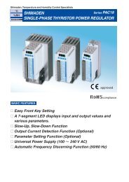
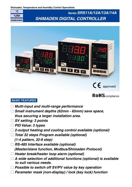
Series SRS11A/12A/13A/14A<br />
<strong>SHIMADEN</strong> <strong>DIGITAL</strong> <strong>CONTROLLER</strong><br />
approved<br />
BASIC FEATURES<br />
compliance<br />
□ Multi-input and multi-range performance<br />
□ Small instrument depths (62mm - 65mm) save space,<br />
thus securing a larger installation area.<br />
□ SV setting: 3 points<br />
□ PID Value: 3 types<br />
□ 2-output heating and cooling control available (optional)<br />
□ Total 32 steps Program available (optional)<br />
(1-4 pattern, 32-8 step)<br />
□ RS-485 Interface available (optional)<br />
(Master/slave function, Modbus/Shimaden Protocol)<br />
□ Heater break/heater loop alarm (optional)<br />
□ A wide selection of additional functions (optional) is available<br />
to suit various needs.<br />
□ Possible to switch off SV/PV value by key operation<br />
□ Parameter mask (non-display) / lock (key lock) function
SMALLER INSTRUMENT DEPTHS<br />
Series SRS11A/12A/13A/14A<br />
Smaller instrument depths save space and secure a larger and flexible installation area.<br />
SRS11A Series<br />
(48×48)<br />
SRS12A Series<br />
(72×72)<br />
SRS13A Series<br />
(96×96)<br />
SRS14A Series<br />
(48×96)<br />
NAMES AND FUNCTIONS<br />
Measured value (PV) display<br />
Target set value (SV) display<br />
Action display<br />
Operating keys<br />
1 Measured value (PV) display<br />
Displays current PV value.<br />
2 Target set value (SV) display<br />
Displays current SV value.<br />
3 Action display<br />
RUN/AT/MAN/OUT1/OUT2/EV1/EV2/<br />
EV3/COM<br />
4 Operating keys<br />
…Parameter key<br />
Displays the next screen in various<br />
screen groups.<br />
…Down key<br />
Decrements setting values.<br />
…Up key<br />
Increments setting values.<br />
…Enter key<br />
Enters setting values.<br />
…RUN/RST key
EXAMPLES OF USE<br />
Series SRS11A/12A/13A/14A<br />
■ EXAMPLE OF 2-OUTPUT CONTROL BY SELECTING CONTROL OUTPUT 2<br />
Output 100%<br />
OUT 1 RA (heating)/OUT 2 DA (cooling) action<br />
Control output 1<br />
(RA characteristics)<br />
Control output 2<br />
(DA characteristics)<br />
Output 100%<br />
OUT 1 RA (heating)/OUT 2 RA (heating) action<br />
Control output 1<br />
(RA characteristics)<br />
Control output 2<br />
(RA characteristics)<br />
Output 0%<br />
Output 0%<br />
−DB<br />
DB=0 DB<br />
−DB DB=0 DB<br />
: Set value (SV) : DB (dead band) : Set value (SV) : DB (dead band)<br />
■ EXAMPLE OF TUNNEL FURNACE PROGRAM<br />
TEMPERATURE CONTROL<br />
Slave<br />
Master Slave<br />
Communication SV communication Communication<br />
■ CT INPUT (CONTROL LOOP ALARM)<br />
For 2 heating stages<br />
SRS10A Series<br />
SRS10A<br />
Series<br />
controller<br />
SRS10A<br />
Series<br />
controller<br />
SRS10A<br />
Series<br />
controller<br />
Heater<br />
Heater<br />
Thyristor<br />
PAC Series<br />
Thyristor<br />
PAC Series<br />
Thyristor<br />
PAC Series<br />
For three-phase<br />
SRS10A Series<br />
Heater<br />
Heater<br />
Electric Oven<br />
Heater<br />
Heater<br />
A<br />
Heater<br />
C<br />
Heater<br />
B<br />
For three-phase<br />
Broken area A B C<br />
CT1 Detectable Undetectable Detectable<br />
CT2 Undetectable Detectable Detectable<br />
■ COMMUNICATION
EXTERNAL DIMENSIONS/PANEL CUTOUT<br />
Series SRS11A/12A/13A/14A
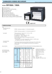
SPECIFICATIONS<br />
Series SRS11A/12A/13A/14A<br />
■ Display<br />
• Display methods<br />
Digital display<br />
: Measured value (PV)/7 segments red LED 4 digits, target set value (SV)/7 segments green LED 4 digits<br />
SRS11A PV height of character: Approx. 12mm SV height of character: Approx. 9mm<br />
SRS12A PV height of character: Approx. 15mm SV height of character: Approx. 12mm<br />
SRS13A PV height of character: Approx. 20mm SV height of character: Approx. 13mm<br />
SRS14A PV height of character: Approx. 12mm SV height of character: Approx. 9mm<br />
Status display<br />
: LED lamp display<br />
Green: RUN, AT, MAN, OUT1, OUT2, COM<br />
Orange: EV1, EV2, EV3<br />
• Display accuracy<br />
: ±(0.25% FS+1 digit) Excluding cold junction temperature compensation accuracy of thermocouple input<br />
Accuracy if set value is lower than -100ºC with K, T, U thermocouples is ±0.7%FS.<br />
Accuracy guarantee not applicable to 400ºC and below of B thermocouple.<br />
• Display accuracy maintaining range : 23ºC±5ºC<br />
• Display resolution : Depends on measuring range and scaling (0.001, 0.01, 0.1, 1)<br />
• Measured value display range : -10 – 110% of measuring range<br />
(Range of Pt-200 – 600ºC is -240 – 680ºC, range of JPt-200 – 500ºC is -240 – 570ºC.)<br />
• Display updating cycle<br />
: 0.25 seconds<br />
■ Setting<br />
• Setting method<br />
• Target value setting range<br />
• Set value limiter<br />
• Key lock<br />
■ Parameter mask/lock function<br />
• Target parameter<br />
PID screen group<br />
PROG screen group<br />
STEP screen group<br />
: By operating 5 keys (PARA, DOWN, UP, ENT, RUN/RST) on the front panel<br />
: Same as measuring range (within setting limiter)<br />
: Individual setting for higher and lower limits, any value is selectable within measuring range.<br />
(Lower limit value
Series SRS11A/12A/13A/14A<br />
Control output resolution : Control output 1: approx. 0.008% (1/13000)<br />
Control output 2: approx. 0.008% (1/13000)<br />
Output accuracy<br />
: Control output 1: ±1.0%FS (5 – 100% output)<br />
Control output 2: ±2.0%FS (5 – 100% output)<br />
• Control output 1<br />
Proportional band (P)<br />
: OFF, 0.1 – 999.9%FS (ON/OFF action by OFF)<br />
Integral time (I)<br />
: OFF, 1 – 6000 seconds (P or PD action by OFF)<br />
Derivative time (D)<br />
: OFF, 1 – 3600 seconds (P or PI action by OFF)<br />
Target value function : OFF, 0.01 – 1.00<br />
ON/OFF hysteresis<br />
: 1 – 999 units (Effective when P=OFF)<br />
Manual reset<br />
: -50.0 – 50.0% (Effective when I=OFF)<br />
Output limiter<br />
: Lower limit 0.0 – 99.9%, higher limit 0.1 – 100.0% (Lower limit value
Series SRS11A/12A/13A/14A<br />
• Time setting<br />
: 0 minutes 0 seconds – 99 minutes 59 seconds/1 step or 0 hours 0 minutes – 99 hours 59 minutes/1 step<br />
• Setting resolution<br />
: 1 minute or 1 second<br />
• Time accuracy<br />
: ±(setting time x 0.005 + 0.25 seconds)<br />
• Setting parameter for each step : SV, step time, PID No.<br />
• No. of pattern execution : Maximum 9999<br />
• PV start<br />
: ON/OFF<br />
• Hold<br />
: Possible either by front panel key input, external control input or communication<br />
• Advance<br />
: Possible either by front panel key input, external control input or communication<br />
• Power failure compensation : None (setting contents are maintained and elapsed time, execution step and number of execution are reset.)<br />
• Guarantee soak zone<br />
: OFF, 1 – 999 units<br />
■ External control input (DI) (option)<br />
• Number of input points<br />
SRS11A<br />
: Maximum 4 points: Exclusive selection with 3 points CT input (DI1, DI2, DI3)<br />
Exclusive selection with 1 point (DI4), control output 2 and event output (EV3)<br />
SRS12A, 13A, 14A : Maximum 4 points: 3 points (DI1, DI2, DI3) no exclusive selection<br />
Exclusive selection with 1 point (DI4), control output 2 and event output (EV3)<br />
• Type of DI assignment<br />
: Selectable from the following 14 types for each DI.<br />
No assignment, EXE1 (RUN1) (control execution/suspension), EXE2 (RUN2) (control execution/<br />
suspension), MAN (manual output), AT (auto tuning), ESV2 (SV external selection 2 bit), ACT1<br />
(output 1 output characteristics), ACT2 (output 2 output characteristics), PROG (programming), HLD<br />
(hold), ADV (advance), PTN2 (start pattern selection 2 bit), PTN3, (start pattern selection 3 bit), L_RS<br />
(unlatching)<br />
• Action input<br />
: Non-voltage contact or open collector (level action) Approx. 5V DC 1mA maximum<br />
• Input minimum holding time : 0.25 seconds<br />
• Isolation<br />
: Not insulated from DI input, system, and CT input but insulated from others<br />
■ CT input (option)<br />
: 2 points selectable when the type of control output (OUT1, OUT2) is contact or SSR<br />
In case of SRS11A, exclusive selection with DI1, DI2 and DI3<br />
• Types of current detection target : Assignable for OUT1 and OUT2<br />
• Current detection method : By CT sensor (sold separately)<br />
• Current capacity<br />
: 30A/50A<br />
• Current setting range<br />
: OFF, 0.1 – 50.0 A (alarm action off when set to OFF)<br />
• Setting resolution : 0.1A<br />
• Current display range : 0.0 – 55.0A<br />
• Display accuracy<br />
: ±2.0 A (for sine wave 50 Hz)<br />
• Alarm action<br />
: Heater break detection when control output ON: Alarm output ON<br />
Heater loop alarm detection when control output OFF: Alarm output ON<br />
• Alarm output : Assignable for event output (EV1, 2, 3)<br />
• Minimum time for action confirmation : ±0.25 seconds for both ON and OFF (each 0.5 second)<br />
• Alarm maintain mode<br />
: Selectable from latching function ON (effective)/OFF (non-effective)<br />
• Standby action<br />
: Selection of "OFF" or "ON" (1, 2, 3) (Standby when power applied only)<br />
• Sampling cycle<br />
: 0.25 seconds<br />
• Isolation<br />
: Not insulated from CT input, input, system and DI but insulated from others<br />
■ Communication function (option) : Exclusive selection with analog output for SRS11A<br />
• Type of communication : EIA standard RS-485<br />
• Communication system : 2-line half duplex start-stop synchronization system<br />
• Communication speed<br />
: 1200, 2400, 4800, 9600, 19200, 38400 bps<br />
• Data format<br />
: Selectable from 7E1, 7E2, 7N1, 7N2, 8E1, 8E2, 8N1, 8N2<br />
• Communication delay time : 1 – 100 (x 0.512 msec)<br />
• Max. number of connections : 32 including host<br />
• Communication address : 1 – 255<br />
• Communication code<br />
: ASCII, MODBUS RTU binary code only<br />
• Communication protocol : Shimaden standard protocol / MODBUS ASCII, RTU<br />
• Other<br />
: Start character and BCC operating method can be selected.<br />
• Communication memory mode : Selectable from EEP, RAM and r_E<br />
• Communication master mode : Can be used as master device when using multiple units<br />
• Start slave address setting : Broadcast, 1 – 255<br />
• End slave address setting : Start address – start address +30<br />
• Write-in data address settng : 0000H – FFFFH<br />
• Communication distance : Max. 500 m (differs according to conditions)<br />
• Isolation<br />
: Isolation for all<br />
■ Analog output (option) : Exclusive selection with communication for SRS11A<br />
• Number of output points : 1 point<br />
• Types of output : Selectable from measured value, target set value (execution SV), control output 1 and control output 2
Series SRS11A/12A/13A/14A<br />
• Output signal/rating : Current 4 – 20 mA DC (max. load resistance 300Ω)<br />
Voltage 0 – 10V DC (max. load current 2 mA)<br />
Voltage 0 – 10mV DC (output resistance 10Ω)<br />
• Output scaling<br />
: Within measuring range or output range (Inversed scaling possible)<br />
• Output accuracy<br />
: ±0.3%FS (for display value)<br />
• Output resolution : Approx. 0.008% (1/13000)<br />
• Output updating cycle<br />
: 0.25 seconds<br />
• Output limiter<br />
: Lower limit 0.0 – 99.9%, higher limit 0.1 – 100.0% (Lower limit value
ORDERING INFORMATION<br />
Series SRS11A/12A/13A/14A<br />
ITEM CODE SPECIFICATIONS<br />
SERIES SRS11A- DIN 48x48 Digital Controller<br />
INPUT<br />
CONTROL OUTPUT 1<br />
CONTROL OUTPUT 2<br />
(OPTION)<br />
8 Multi-input<br />
6 Voltage (V)<br />
Y<br />
I<br />
P<br />
V<br />
Thermocouple: B, R, S, K, E, J, T, N, PLII, WRe5-26,<br />
{U, L (DIN43710)}, AuFe-Cr<br />
R.T.D.: Pt100/JPt100<br />
Voltage (mV): -10 – 10, 0 – 10, 0 – 20,<br />
0 – 50, 0 – 100, 10 – 50mV DC<br />
-1 – 1, 0 – 1, 0 – 2, 0 – 5, 1 – 5, 0 – 10V DC<br />
Input resistance: Min. 500kΩ<br />
Scaling Possible<br />
(inverse scaling<br />
impossible)<br />
Range: -1999 – 9999<br />
Span: 10 – 10000<br />
Contact: 1a, Contact capacity: 240V AC 2A/resistive load<br />
Proportional cycle: 1 – 120 sec.<br />
Current: 4 – 20mA DC<br />
Load resistance: 600Ω max.<br />
SSR drive voltage: 12V±1.5V DC/30mA max.<br />
Proportional cycle: 1 – 120 sec.<br />
Voltage: 0 – 10V DC<br />
Load current: 2mA max.<br />
N- None<br />
Contact: 1a, Contact capacity: 240V AC 2A/resistive load<br />
Y-<br />
Proportional cycle: 1 – 120 sec.<br />
Current: 4 – 20mA DC<br />
I-<br />
Load resistance: 600Ω max.<br />
SSR drive voltage: 12V±1.5V DC/30mA max.<br />
P-<br />
Proportional cycle: 0.5 – 120 sec.<br />
Voltage: 0 – 10V DC<br />
V-<br />
Load current: 2mA max.<br />
Additional event output E- Additional event output 1 point (EV3)<br />
Additional external control<br />
D- Additional external control input 1 point (DI4)<br />
input signal (DI)<br />
90- 100 – 240V AC±10%, 50/60Hz<br />
POWER SUPPLY<br />
08- 24V AC/DC±10%, 50/60Hz<br />
N<br />
None<br />
PROGRAM FUNCTION (OPTION)<br />
P Max. 4 patterns Total number of steps: 32<br />
0 None<br />
EVENT OUTPUT (OPTION)<br />
1 Event output 2 points (EV1, EV2)<br />
0 None<br />
ANALOG OUTPUT/<br />
3 0 – 10mVDC Output resistance: 10Ω<br />
CONMMUNICATION<br />
4 4 – 20mADC Resistive load: 300Ω max.<br />
FUNCTION (OPTION)<br />
6 0 – 10VDC Load current: 2mA max.<br />
5 RS-485 (Shimaden standard protocol, MODBUS protocol)<br />
0 None<br />
EXTERNAL INPUT CONTROL SIGNAL (DI)/<br />
1 CT input 2 points Note: Available only when control output 1 or 2 is Y or P.<br />
CT INPUT (OPTION)/Note: CT sold separately<br />
2 Control input 3 points (DI1, DI2, DI3)<br />
0 Without<br />
REMARKS<br />
9 With<br />
OPTIONAL ACCESSORIES<br />
Name Code Remarks<br />
CT QCC01 CT for 30A (CTL-6-S)<br />
CT QCC02 CT for 50A (CTL-12-S36-8)<br />
Shunt resistor QCS002 250Ω ±0.1% External receiving impedance for current input<br />
Terminal cover QCR001 For SRS11A
ORDERING INFORMATION<br />
Series SRS11A/12A/13A/14A<br />
ITEM CODE SPECIFICATIONS<br />
SERIES<br />
INPUT<br />
SRS12A-<br />
SRS13A-<br />
SRS14A-<br />
CONTROL OUTPUT 1<br />
CONTROL OUTPUT 2<br />
(OPTION)<br />
8 Multi-input<br />
6 Voltage (V)<br />
Y<br />
I<br />
P<br />
V<br />
DIN 72x72 Digital Controller<br />
DIN 96x96 Digital Controller<br />
DIN 96x48 Digital Controller<br />
Thermocouple: B, R, S, K, E, J, T, N, PLII, WRe5-26,<br />
{U, L (DIN43710)}, AuFe-Cr<br />
R.T.D.: Pt100/JPt100<br />
Voltage (mV): -10 – 10, 0 – 10, 0 – 20, 0 – 50,<br />
0 – 100, 10 – 50mV DC<br />
-1 – 1, 0 – 1, 0 – 2, 0 – 5, 1 – 5, 0 – 10V DC<br />
Input resistance: Min. 500kΩ<br />
Scaling Possible<br />
(inverse scaling<br />
impossible)<br />
Range: -1999 – 9999<br />
Span: 10 – 10000<br />
Contact: 1a, Contact capacity: 240V AC 2A/resistive load<br />
Proportional cycle: 1 – 120 sec.<br />
Current: 4 – 20mA DC<br />
Load resistance: 600Ω max.<br />
SSR drive voltage: 12V±1.5V DC/30mA max.<br />
Proportional cycle: 1 – 120 sec.<br />
Voltage: 0 – 10V DC<br />
Load current: 2mA max.<br />
N- None<br />
Contact: 1a, Contact capacity: 240V AC 2A/resistive load<br />
Y-<br />
Proportional cycle: 1 – 120 sec.<br />
Current: 4 – 20mA DC<br />
I-<br />
Load resistance: 600Ω max.<br />
SSR drive voltage: 12V±1.5V DC/30mA max.<br />
P-<br />
Proportional cycle: 1 – 120 sec.<br />
Voltage: 0 – 10V DC<br />
V-<br />
Load current: 2mA max.<br />
Additional event output E- Additional event output 1 point (EV3)<br />
Additional external<br />
D- Additional external control input 1 point (DI4)<br />
control input signal (DI)<br />
90- 100 – 240V AC±10%, 50/60Hz<br />
POWER SUPPLY<br />
08- 24V AC/DC±10%, 50/60Hz<br />
N<br />
None<br />
PROGRAM FUNCTION (OPTION)<br />
P Max. 4 patterns Total number of steps: 32<br />
0 None<br />
EVENT OUTPUT (OPTION)<br />
1 Event output 2 points (EV1, EV2)<br />
0 None<br />
3 0 – 10mVDC Output resistance: 10Ω<br />
ANALOG OUTPUT (OPTION)<br />
4 4 – 20mADC Resistive load: 300Ω max.<br />
6 0 – 10VDC Load current: 2mA max.<br />
CT INPUT (OPTION)/Note: CT sold separately<br />
EXTERNAL INPUT CONTROL SIGNAL (DI) (OPTION)<br />
CONMMUNICATION FUNCTION (OPTION)<br />
REMARKS<br />
0 None<br />
1 CT input 2 points Note: Available only when control output 1 or 2 is Y or P.<br />
0 None<br />
2 Control input 3 points (DI1, DI2, DI3)<br />
0 None<br />
5 RS-485 (Shimaden standard protocol, MODBUS protocol)<br />
0 Without<br />
9 With<br />
OPTIONAL ACCESSORIES<br />
Name Code Remarks<br />
CT QCC01 CT for 30A (CTL-6-S)<br />
CT QCC02 CT for 50A (CTL-12-S36-8)<br />
Shunt resistor QCS002 250Ω ±0.1% External receiving impedance for current input<br />
Terminal cover<br />
QCR002 For SRS12A (3 pcs./set)<br />
QCR007 For SRS13A, SRS14A (2 pcs./set)
MEASURING RANGE CODES<br />
Series SRS11A/12A/13A/14A<br />
Multi-input<br />
Thermocouple<br />
R.T.D.<br />
Voltage<br />
(mV)<br />
Voltage (V)<br />
Input Type Code Measuring range<br />
Kelvin<br />
B 01 *1 0 – 1800 °C 0 – 3300 °F<br />
R 02 0 – 1700 °C 0 – 3100 °F<br />
S 03 0 – 1700 °C 0 – 3100 °F<br />
04 *2 -199.9 – 400.0 °C -300 – 750 °F<br />
K<br />
05 0.0 – 800.0 °C 0 – 1500 °F<br />
06 0 – 1200 °C 0 – 2200 °F<br />
E 07 0 – 700 °C 0 – 1300 °F<br />
J 08 0 – 600 °C 0 – 1100 °F<br />
T 09 *2 -199.9 – 200.0 °C -300 – 400 °F<br />
N 10 0 – 1300 °C 0 – 2300 °F<br />
PLII *3 11 0 – 1300 °C 0 – 2300 °F<br />
WRe5-26 *4 12 0 – 2300 °C 0 – 4200 °F<br />
U *5 13 *2 -199.9 – 200.0 °C -300 – 400 °F<br />
L *5 14 0 – 600 °C 0 – 1100 °F<br />
K 15 *6 10.0 – 350.0 K 10.0 – 350.0 K<br />
AuFe-Cr 16 *7 0.0 – 350.0 K 0.0 – 350.0 K<br />
K 17 *6 10 – 350 K 10 – 350 K<br />
AuFe-Cr 18 *7 0 – 350 K 0 – 350 K<br />
30 -100.0 – 350.0 °C -150.0 – 650.0 °F<br />
31 -200 – 600 °C -300 – 1100 °F<br />
Pt100<br />
32 -100.0 – 100.0 °C -150.0 – 200.0 °F<br />
33 -50.0 – 50.0 °C -50.0 – 120.0 °F<br />
34 0.0 – 200.0 °C 0.0 – 400.0 °F<br />
35 -200 – 500 °C -300 – 1000 °F<br />
36 -100.0 – 100.0 °C -150.0 – 200.0 °F<br />
JPt100 37 -50.0 – 50.0 °C -50.0 – 120.0 °F<br />
38 0.0 – 200.0 °C 0.0 – 400.0 °F<br />
39 -100.0 – 350.0 °C -150.0 – 650.0 °F<br />
40 -199.9 – 550.0 °C -300 – 1000 °F<br />
Pt100<br />
41 0.0 – 350.0 °C 0.0 – 650.0 °F<br />
42 0.0 – 550.0 °C 0 – 1000 °F<br />
43 -199.9 – 500.0 °C -300 – 1000 °F<br />
JPt100 44 0.0 – 350.0 °C 0.0 – 650.0 °F<br />
45 0.0 – 500.0 °C 0 – 1000 °F<br />
-10 – 10 71<br />
0 – 10 72<br />
Measuring range can be set by scaling function within the following range.<br />
0 – 20 73<br />
Initial value: 0.0 – 100.0<br />
0 – 50 74<br />
10 – 50 75 Scaling range: -1999 – 9999 units<br />
0 – 100 76 Span: 10 – 10,000 units<br />
-1 – 1 81 Decimal point position: None, 1/2/3 digits following decimal point<br />
0 – 1 82 Lower limit value is less than higher limit value.<br />
0 – 2 83<br />
NOTE: For current input, install input terminals of the specified receiving<br />
0 – 5 84<br />
impedance (250Ω) and use code 84 (0 – 20 mA) or 85 (4 – 20 mA).<br />
1 – 5 85<br />
0 – 10 86<br />
Thermocouple: B, R, S, K, E, J, T, N: JIS/IEC<br />
R.T.D. Pt100: JIS/IEC JPt100<br />
*1 Thermocouple B: Accuracy guarantee not applicable to 400˚C or below.<br />
*2 Thermocouple K, T, U: Accuracy of those readings below -100.0˚C is 0.75% FS.<br />
*3 Thermocouple PLII: Platinel<br />
*4 Thermocouple WRe5-26: ASTM E988-96<br />
*5 Thermocouple U, L: DIN 43710<br />
*6. Thermocouple K (Kelvin) accuracy<br />
Temperature range<br />
10.0 – 30.0 K (2.0%FS + [CJ error X 20] K + 1K)<br />
30.0 – 70.0 K (1.0%FS + [CJ error X 7] K + 1K)<br />
70.0 – 170.0 K (0.7%FS + [CJ error X 3] K + 1K)<br />
170.0 – 270.0 K (0.5%FS + [CJ error X 1.5] K + 1K)<br />
270.0 – 350.0 K (0.3%FS + [CJ error X 1] K + 1K)<br />
NOTE: For current input, install input terminals of the specified receiving impedance (250Ω) and use code 84 (0 – 20 mA) or 85 (4 – 20 mA).<br />
NOTE: Unless otherwise specified, the measuring range will be set as follows when shipped from the factory:<br />
Input Standard/rating Measuring range<br />
Multi-input K thermocouple 0.0 – 800.0˚C<br />
Voltage (V) 0 – 10V DC 0.0 – 100.0 no legend<br />
*7. Thermocouple Metal-chromel (AuFe-Cr) (Kelvin) accuracy<br />
Temperature range<br />
0.0 – 30.0 K (0.7%FS + [CJ error X 3] K + 1K)<br />
30.0 – 70.0 K (0.5%FS + [CJ error X 1.5] K + 1K)<br />
70.0 – 170.0 K (0.3%FS + [CJ error X 1.2] K + 1K)<br />
170.0 – 280.0 K (0.3%FS + [CJ error X 1] K + 1K)<br />
280.0 – 350.0 K (0.5%FS + [CJ error X 1] K + 1K)
SRS11A<br />
Series SRS11A/12A/13A/14A<br />
SRS12A<br />
External control<br />
input signal<br />
Power supply<br />
17<br />
18<br />
19<br />
20<br />
COM<br />
DI1<br />
DI2<br />
DI3<br />
9<br />
10<br />
L<br />
N<br />
100<br />
240 V AC<br />
50/60 Hz<br />
9<br />
10<br />
L<br />
N<br />
24 V<br />
AC/DC<br />
Control output 1<br />
Current output<br />
SSR drive<br />
Relay contact<br />
voltage output<br />
Voltage output<br />
Communication<br />
RS-485<br />
1<br />
2<br />
1<br />
2<br />
3<br />
17<br />
18<br />
19<br />
9<br />
10<br />
11<br />
11<br />
12<br />
11<br />
12<br />
Event output<br />
COM<br />
EV1<br />
EV2<br />
3<br />
4<br />
5<br />
4<br />
5<br />
6<br />
7<br />
8<br />
20<br />
21<br />
22<br />
23<br />
24<br />
12<br />
13<br />
14<br />
15<br />
16<br />
Control output 2<br />
Relay contact<br />
13<br />
14<br />
Current output<br />
SSR drive<br />
voltage output<br />
Voltage output<br />
13<br />
14<br />
Additional<br />
event output<br />
(EV3)<br />
13<br />
14<br />
EV3<br />
Additional<br />
external<br />
control input<br />
signal<br />
(DI4)<br />
DI4<br />
13<br />
14<br />
Input<br />
CT input<br />
Analog output<br />
TC<br />
6<br />
7<br />
Multi input<br />
RTD<br />
A<br />
B<br />
B<br />
6<br />
7<br />
8<br />
Voltage (mV)<br />
6<br />
7<br />
Voltage (V)<br />
6<br />
7<br />
Current (mA)<br />
6<br />
7<br />
CT1<br />
CT2<br />
21<br />
22<br />
23<br />
24<br />
15<br />
16
SRS13A/SRS14A<br />
Series SRS11A/12A/13A/14A<br />
OPTIONAL TERMINAL COVER<br />
QCR001 QCR002 QCR007<br />
13.6<br />
13.6<br />
63.5<br />
× 3 pcs.<br />
91<br />
× 2 pcs.<br />
47<br />
44<br />
15<br />
17.6<br />
SRS11A SRS12A SRS13A & SRS14A
ACCESSORIES REQUIRED FOR CT INPUT<br />
Series SRS11A/12A/13A/14A<br />
To CT input<br />
terminal of controller<br />
(no polarity)<br />
Heater (load) wiring<br />
CT FOR 30A (QCC01)<br />
CT FOR 50A (QCC02)<br />
10.5<br />
5.8<br />
21<br />
15<br />
7.5<br />
3<br />
10 25<br />
30<br />
2.8<br />
40 9<br />
40<br />
5 30 5<br />
30 40<br />
15<br />
2.36<br />
12<br />
2-3.5<br />
2-M3<br />
Unit: mm<br />
Warning<br />
• The SRS Series is designed for the control of temperature, humidity and other physical values of general industrial equipment.<br />
It is not to be used for any purpose which regulates the prevention of serious effects on human life or safety.<br />
Caution<br />
• If the possibility of loss or damage to your system or property as a result of failure of any part of the process exists, proper<br />
safety measures must be made before the instrument is put into use so as to prevent the occurrence of trouble.<br />
ISO9001/ISO14001<br />
Temperature and Humidity Control Specialists<br />
(The contents of this brochure are subject to change without notice.)<br />
Head Office: 2-30-10 Kitamachi, Nerima-Ku, Tokyo 179-0081 Japan<br />
Phone: +81-3-3931-7891 Fax: +81-3-3931-3089<br />
E-MAIL: exp-dept@shimaden.co.jp URL: http://www.shimaden.co.jp<br />
11BSRS10A300ILC