SHIMADEN DIGITAL CONTROLLER
SHIMADEN DIGITAL CONTROLLER
SHIMADEN DIGITAL CONTROLLER

You also want an ePaper? Increase the reach of your titles
YUMPU automatically turns print PDFs into web optimized ePapers that Google loves.
Shimaden, Temperature and Humidity Control Specialists<br />
°C<br />
%RH<br />
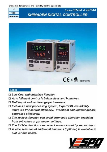
Series SR73A & SR74A<br />
<strong>SHIMADEN</strong> <strong>DIGITAL</strong> <strong>CONTROLLER</strong><br />
BASIC<br />
Low Cost with Interface Function<br />
Auto / Manual control is balanceless and bumpless.<br />
Multi-input and multi-range performance<br />
Includes a new processing system, Expert PID, remarkably<br />
improved PID control efficiency; overshoot and undershoot are<br />
controlled effectively.<br />
The keylock function can avoid erroneous operation resulting<br />
from set values or parameter settings.<br />
The PV bias function can correct errors caused by sensor input.<br />
A wide selection of additional functions (optional) is available to<br />
suit various needs.
SPECIFICATIONS<br />
Display<br />
• Digital display:<br />
• Parameter display:<br />
• Action display:<br />
• Display accuracy:<br />
Measured value (PV)7-segment<br />
green LED 4 digits<br />
Set value (SV)7-segment orange<br />
LED 4 digits<br />
7-segment LED for PV and SV<br />
Green LEDs for 5 points of output<br />
(OUT), auto tuning (AT), stand-by<br />
mode (STBY), communication<br />
(COM) and manual output (MAN).<br />
Red LEDs for 2 points of alarm<br />
(AH, AL / HB).<br />
±(0.5% FS+1 digit)excluding cold<br />
junction temperature<br />
compensation accuracy in the<br />
case of the thermocouple input.<br />
±5% FS for temperatures below<br />
400°C(750°F) of thermocouple B.<br />
• Display accuracy range: 23±5°C(18~28°C)<br />
•Display resolution:<br />
Depends on measuring range<br />
(0.001, 0.01, 0.1, 1)<br />
• Measured display range: –10~110%(–210~680°C for<br />
–200~600°C of R.T.D. input)<br />
Setting<br />
• Setting:<br />
• Setting range:<br />
Input<br />
• Type of input:<br />
• Thermocouple:<br />
By 5 front key switches<br />
Same as measuring range.<br />
Multiple input of Thermocouple,<br />
R.T.D., Voltage (mV), or Voltage<br />
(V), or Current 4~20mA DC by<br />
code selection<br />
B, R, S, K, E, J, T, N, {U, L(DIN<br />
43710)} Refer to Measuring range<br />
code table.<br />
100Ω max.<br />
500kΩ min.<br />
External resistance:<br />
Input impedance:<br />
Burnout:<br />
Standard feature (up scale)<br />
Cold junction<br />
temperature<br />
compensation accuracy: ±2°C (5~45°C)<br />
±5°C to the negative side of<br />
measuring range in case of T and<br />
U input.<br />
•R.T.D.:<br />
Amperage:<br />
Lead wire tolerable<br />
resistance:<br />
JIS Pt100 / JPt100 3-wire type<br />
Approx. 0.25mA<br />
5Ω max. / wire (The 3 lead wires<br />
should have same resistance.)<br />
• Voltage:<br />
0~10, 10~50, 0~100mV DC or<br />
0~1, 1~5, 0~10V DC<br />
Input impedance: 500kΩ min.<br />
•Current:<br />
4~20mA DC<br />
Receiving impedance: 250Ω<br />
• Input scaling function: Scaling possible for voltage (mV,<br />
V) or current (mA) input.<br />
Scaling range: –1999~9999 counts.<br />
Span:<br />
100~5000 counts<br />
Position of decimal point: None, 0.0, 0.00, 0.000<br />
• Sampling cycle: 0.5 sec.<br />
• PV bias range: ±200 unit<br />
• PV filter:<br />
0~100 sec. (0=without filter)<br />
Control<br />
•Control mode:<br />
• Proportional band (P):<br />
Auto tuning PID / ON-OFF control<br />
Off, 0.1~999.9% FS (Off setting:<br />
On-Off action)<br />
• Integral time(I): Off, 1~6000 sec. (Off setting: P-<br />
PD action)<br />
• Derivative time (D): Off, 1~3600 sec. (Off setting: P-<br />
PI action)<br />
• Manual reset (MR):<br />
•Output limiter:<br />
–50.0~50.0% (Valid when P≠OFF<br />
and I=OFF)<br />
Lower limit limiter 0~99%, Higher<br />
limit limiter 1~100% (Priority given<br />
to lower limit limiter)<br />
• Soft start of output: Off, 1~100 sec.<br />
• ON / OFF hysteresis: 1~999 units.<br />
• Proportional cycle: 1~120 sec. (Factory-set value: 30<br />
sec. for contact output and 3 sec.<br />
for SSR drive voltage output.)<br />
• Control output<br />
characteristics:<br />
RA / DA selectable (set to RA<br />
when shipped)<br />
•Set value function (SF): OFF(Off=0.00) and 0.01~1.00<br />
Control Output<br />
• Contact output:<br />
• Current output:<br />
240V AC 2.5A / resistive load:<br />
1.5A / inductive load<br />
4~20mA DC / load resistance:<br />
600Ω max.<br />
• SSR drive voltage output: 15±3V DC (with load resistance at<br />
1.5kΩ) / load current: 20mA<br />
maximum<br />
• Voltage output:<br />
0~10V DC / load current: 2mA<br />
maximum<br />
Manual Control<br />
•Output setting range: 0~100% (setting resolution: 1%)<br />
but within range set by higher /<br />
lower output limiters.<br />
• Auto / manual switching: Balanceless bumpless. Within<br />
proportional band range.<br />
Communication (Optional)<br />
•Signal level:<br />
EIA standards, conforming with<br />
RS-422A and RS-485.<br />
• Communication System: RS-422A 4-wire half duplex multidrop<br />
system. RS-485 2-wire half<br />
duplex multi-drop (bus) system.<br />
• Synchronous system: Start-stop synchronous system.<br />
• Data format:<br />
Data length 7 bits, even parity,<br />
stop bit 1.<br />
• Communication address: Machine numbers are set in a<br />
range from 0 to 99<br />
• Communication rate: 1200, 2400, 4800 and 9600 bps.<br />
• Communication delay: To be set in a range from 0 to 255<br />
(Setting possible only in the case<br />
of RS-485.)<br />
• Communication distance:RS-422A maximum 1200m<br />
(depending on conditions) RS-485<br />
maximum 500m (depending on<br />
conditions)<br />
• Transmission procedure: No procedure.<br />
• Communication code:<br />
• Control signal:<br />
• Error detection:<br />
• Connectable number of<br />
apparatuses:<br />
Conforming with ASCII codes.<br />
Not used.<br />
Vertical parity (even parity)<br />
checking. BCC (block check<br />
character) checking.<br />
Possible to connect 100 units<br />
maximum (including the host,<br />
depending on conditions)
Series SR73A & SR74A<br />
Alarm Output (Optimal)<br />
• Number of alarm points: 2 (AH and AL / HB, both for<br />
normal open and common)<br />
Alarm Type: Selectable from the following 9<br />
combinations. (5 through 8 are<br />
selectable only when apparatus<br />
has heater break alarm function.)<br />
0. Not assigned<br />
1. Higher limit deviation value + lower limit deviation value<br />
without inhibit action<br />
2. Higher limit absolute value + lower limit absolute value<br />
without inhibit action<br />
3. Higher limit deviation value + lower limit deviation value<br />
with inhibit action<br />
4. Higher limit absolute value + lower limit absolute value<br />
with inhibit action<br />
5. Higher limit deviation value without inhibit action + heater<br />
break<br />
6. Higher limit absolute value without inhibit action + heater<br />
break<br />
7. Higher limit deviation value with inhibit action + heater<br />
break<br />
8. Higher limit absolute value with inhibit action + heater<br />
break<br />
• Alarm setting range:<br />
Deviation value:<br />
Higher limit and lower limit<br />
absolute value alarms: Within full<br />
scale of measuring range<br />
Higher limit: 0~2000 unit<br />
Lower limit: –1999~0 unit<br />
On-Off action<br />
• Alarm action:<br />
• Alarm action hysteresis: Fixed to 0.2% of the measuring<br />
range<br />
• Alarm output / rating: Contact la (common) / 240V AC<br />
1.5A (resistive load)<br />
Heater Break Alarm (option)<br />
This function can be added if the instrument has an alarm<br />
option and the control output is the contact type or the SSR<br />
drive voltage type.<br />
• Alarm action:<br />
• Current setting range:<br />
Heater amperage detected by<br />
externally attached CT. (except<br />
0~5V DC input) Alarm output On<br />
upon detection of heater break<br />
while control output is On.<br />
Off, 0.1~50.0A (Alarm action<br />
stops when Off is set.) or, Off, 1-<br />
500A (when 0~5V DC for CT input<br />
is selected)<br />
0.1A or 1A<br />
• Setting resolution:<br />
• Amperage display: 0.0~55.0A or 0~550A<br />
• Display accuracy:<br />
•Minimum time for<br />
action confirmation:<br />
•Alarm holding:<br />
• Sampling cycle:<br />
5% FS (when sine wave is 50 Hz)<br />
or 1% FS (in case of 0~5V DC<br />
input)<br />
On time: 500 msec.<br />
Selectable between Lock<br />
(holding) and Real (no holding)<br />
2 sec.<br />
Set Value Bias (Option)<br />
• Setting range:<br />
• Setting resolution:<br />
• Action input:<br />
–1999~2000 unit<br />
Same as display resolution<br />
Non-voltage contact (bias in<br />
action when SB terminal is<br />
closed)<br />
Others<br />
• Data storage:<br />
By non-volatile memory<br />
(EEPROM)<br />
• Isolation:<br />
Input, control output,<br />
communication and alarm output<br />
circuits are isolated from each<br />
other. Input, set value bias and<br />
CT input circuits are not isolated<br />
from each other.<br />
•Ambient conditions for<br />
use Temperature/humidity<br />
ranges:<br />
–10~50°C and below 90%RH (on<br />
the condition that there is no dew<br />
condensation)<br />
•Height:<br />
2000 m above sea level or lower<br />
• Installation category: II<br />
• Degree of pollution: 2<br />
• Supply voltage /<br />
frequency:<br />
100-260V AC±10% (50 / 60 Hz)<br />
• Power consumption:<br />
• Applicable standard:<br />
• Insulation resistance:<br />
• Dielectric strength:<br />
•Protective structure:<br />
•Material:<br />
• External dimensions<br />
SR73A:<br />
SR74A:<br />
•Mounting:<br />
• Panel thickness:<br />
• Panel cutout<br />
SR73A:<br />
SR74A:<br />
•Weight<br />
SR73A:<br />
SR74A:<br />
12 VA max.<br />
Safety: IEC1010-1<br />
EMC EMI (emission): EN50081-1<br />
EMS (immunity): EN50082-2<br />
Between input / output terminal<br />
and power supply terminal: 500V<br />
DC 20 MΩ minimum Between<br />
input / output terminal and<br />
protective conductor terminal:<br />
500V DC 20 MΩ minimum<br />
1 min. at 2300V AC between input<br />
/ output terminal and power<br />
supply terminal 1 min. at 1500V<br />
AC between power supply<br />
terminal and protective conductor<br />
terminal<br />
Only front panel has simple dustproof<br />
and drip-proof structure<br />
PPO resin molding (equivalent to<br />
UL94V-1)<br />
H96 × W96 × D110<br />
(panel depth: 100)mm<br />
H96 × W48 × D110<br />
(panel depth: 100)mm<br />
Push-in panel (one-touch mount)<br />
1.0~3.5 mm<br />
H92 × W92mm<br />
H92 × W45mm<br />
Approx. 400g<br />
Approx. 300g
ALARM OUTPUT (OPTIONAL)<br />
Series SR73A & SR74A<br />
Alarm Method Alarm Setting Range Action<br />
Higher limit deviation value alarm<br />
0~2000 unit<br />
OFF<br />
ON<br />
Lower limit deviation value alarm<br />
–1999~0 unit<br />
ON<br />
OFF<br />
Higher limit absolute value alarm<br />
within measuring range<br />
OFF<br />
ON<br />
Lower limit absolute value alarm within measuring range ON OFF<br />
Main setting<br />
Alarm setting<br />
Alarm Type:<br />
Alarm setting range:<br />
Alarm action:<br />
Alarm action hysteresis:<br />
Alarm output / rating:<br />
•Selectable from combination of the following 9 types<br />
Alarm code<br />
AH With/Without AL/HB With/Without<br />
assignment inhibit action assignment inhibit action<br />
0( 0 ) Not assigned ----- Not assigned -----<br />
1( 1 )<br />
2( 2 )<br />
3( 3 )<br />
4( 4 )<br />
5( 5 )<br />
6( 6 )<br />
7( 7 )<br />
8( 8 )<br />
Higher limit Without Lower limit Without<br />
deviation value inhibit action deviation value inhibit action<br />
Higher limit Without Lower limit Without<br />
absolute value inhibit action absolute value inhibit action<br />
Higher limit With Lower limit With<br />
deviation value inhibit action deviation value inhibit action<br />
Higher limit With Lower limit With<br />
absolute value inhibit action absolute value inhibit action<br />
Higher limit Without<br />
deviation value inhibit action<br />
Heater break -----<br />
Higher limit Without<br />
absolute value inhibit action<br />
Heater break -----<br />
Higher limit With<br />
deviation value inhibit action<br />
Heater break -----<br />
Higher limit With<br />
absolute value inhibit action<br />
Heater break -----<br />
Higher limit and lower limit absolute value alarms: Within measuring range<br />
Deviation value: Higher limit: 0~2000 unit*<br />
Lower limit: –1999~0 unit* In case SV is out of the<br />
} measuring range, higher and<br />
lower limit values of the<br />
measuring range become the<br />
action points.<br />
On-Off action<br />
Fixed to 0.2% of the measuring range<br />
Contact 1a (common) / 240V AC 1.5A (resistive load)<br />
WIRING EXAMPLE I<br />
•Contact output (Y1)<br />
422A 485<br />
SG<br />
SD+ +<br />
SD –<br />
RD+<br />
RD–<br />
SG<br />
Thermocouple<br />
1<br />
2<br />
3<br />
4<br />
5<br />
6<br />
7<br />
21<br />
SB<br />
22<br />
11<br />
12<br />
13<br />
14<br />
15<br />
16<br />
17<br />
8<br />
18<br />
CT<br />
9<br />
19<br />
23 24<br />
10 20<br />
Heater<br />
SV bias non-voltage contact (closed for input)<br />
Fuse<br />
250V AC 0.5A<br />
Higher limit alarm<br />
Lower limit alarm or<br />
healer break alarm<br />
CT<br />
MC<br />
Instrurment power supply<br />
100-240V AC<br />
50/60Hz<br />
MC : Electro-magnetic switch<br />
Power supply<br />
200V AC<br />
50/60Hz<br />
Note:<br />
1. The heater break alarm function<br />
(optional) can be added when the control<br />
output is of the contact (Y1) or the SSR<br />
drive voltage (P1) type.<br />
2. Fuse: Since the instrument dose not<br />
have a built-in fuse, do not forget<br />
to install a fuse in the power circuit<br />
to be connected to the power<br />
terminal. The fuse should be<br />
positioned between the switch or<br />
the breaker and the instrument<br />
and be attached to the L side of<br />
the power terminal. Fuse Rating:<br />
250V AC 0.5A / medium lagged or<br />
lagged type. Use a fuse which<br />
meets the requirements of IEC127.
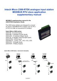
Series SR73A & SR74A<br />
•Current output (I1)<br />
Control output portion only<br />
SR73, SR74<br />
+<br />
14<br />
–<br />
15<br />
16<br />
+<br />
–<br />
4-20mA DC<br />
600Ω Max.<br />
Operating<br />
power supply<br />
PAC series<br />
(thyristor)<br />
Heater<br />
•SSR drive voltage (P1)<br />
Control output portion only<br />
SR73, SR74<br />
+<br />
14<br />
–<br />
15<br />
16<br />
+<br />
–<br />
15V DC<br />
20mA Max.<br />
PAC series<br />
(SSR)<br />
Heater<br />
Operating<br />
power supply<br />
WIRING EXAMPLE II<br />
How to connect SR73A or 74A with host computer<br />
•Control signals<br />
Since the apparatus is provided with input / output<br />
transmitting and receiving data lines and an earthing line<br />
for signals but not with any other signal line, control signals<br />
should be processed by the host side.<br />
The method of processing differs from system to system<br />
and connection details should meet requirements of the<br />
host computer. Examples of connection are shown in the<br />
following.<br />
•Connection of RS-422A<br />
(1) The logical levels of input and output of this apparatus<br />
are basically as follows:<br />
Mark state **–SD+)<br />
However, since the impedance of SD+ and SD– of this<br />
apparatus is high until just before transmission, the<br />
above levels are output just before commencing<br />
transmission.<br />
(2) Example of Connection of RS-422A<br />
Host computer<br />
FG (Earthing for protection)<br />
SD+<br />
SD–<br />
RD+<br />
RD–<br />
SG<br />
Terminal resistance (510Ω)<br />
Shielding wire<br />
SR73A and 74A Controllers 1<br />
terminal No.<br />
SD+<br />
SD–<br />
2<br />
3<br />
Transmitted data<br />
RD+ 4<br />
RD– 5<br />
Received data<br />
SG 1 Earthing for signal<br />
SR73A and 74A Controllers 2<br />
terminal No.<br />
SD+<br />
SD–<br />
2<br />
3<br />
Transmitted data<br />
RD+ 4<br />
RD– 5<br />
Received data<br />
SG 1 Earthing for signal<br />
Note: Some line converters between RS-232C and RS-<br />
422A may have the following indication for terminal<br />
(connector) output. If that is the case, logical levels<br />
Example: Mark state T x D+ > T x D-<br />
Mark state T x D+ < T x D-<br />
Line converter<br />
FG (Earthing for protection)<br />
T x D+<br />
T x D–<br />
R x D+<br />
R x D–<br />
SG<br />
Shielding wire<br />
SR73A and 74A Controllers<br />
terminal No.<br />
SD+ 2<br />
SD– 3<br />
RD+ 4<br />
RD– 5<br />
SG 1<br />
• Connenction of RS-485<br />
(1) The logical levels of input and output of this apparatus<br />
are basically as follows:<br />
Mark state –Terminal < + Terminal<br />
(including the state in which communication is not<br />
carried out)<br />
Space state –Terminal > + Terminal<br />
However, since the impedance of +terminal and<br />
–terminal of this apparatus is high until just before<br />
transmission, the above levels are output just before<br />
commencing transmission.<br />
(2) Example of Connection of RS-485<br />
Host computer<br />
FG (Earthing for protection)<br />
(+)<br />
(–)<br />
SG<br />
Terminal resistance (510Ω)<br />
Shielding wire<br />
SR73A and 74A Controllers 1<br />
terminal No.<br />
(+)<br />
(–)<br />
SG<br />
SR73A and 74A Controllers 2<br />
terminal No.<br />
(+)<br />
(–)<br />
SG<br />
• Terminal resistance<br />
As SR73A and SR74A are not provided with terminal<br />
resistance, connect a 510Ω resistance to only the last (the<br />
furthest from the host) station.<br />
Note: If terminal resistance is connected to two or more,<br />
correct action is not guaranteed.<br />
2<br />
3<br />
1<br />
2<br />
3<br />
1
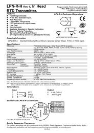
ORDERING INFORMATION<br />
Series SR73A & SR74A<br />
ITEM CODE SPECIFICATIONS<br />
SR73A- H963W963D110 DIN size digital controller for auto tuning with interface function PID control<br />
SERIES<br />
SR74A-<br />
H963W483D110 DIN size digital controller for auto tuning with interface function PID control<br />
·Thermocouple B, R, S, K, E, J, T, N<br />
Value set at<br />
{U, (DIN43710)}<br />
8<br />
K 0~1200˚C<br />
Multi input ·R.T.D. Pt100/JPt100<br />
INPUT<br />
when shipped<br />
·Voltage (mV) 0~10, 10~50, 0~100mV DC<br />
4 Current (mA) 4~20mA DC Value set at 4~20mA/0~100.0 when shipped<br />
6 Voltage (V) 0~1, 1~5, 0~10V DC Value set at 0~1 V/0~100.0 when shipped<br />
Contact (1c) Contact capacity : 240V AC 2.5A/resistive load<br />
Y1-<br />
Proportional cycle fixed to 20sec.<br />
RA(heating<br />
CONTROL I1- Current 4~20mA DC Load resistance : 600Ω max. characteristics)<br />
OUTPUT<br />
SSR drive voltage Output rating : 15 ± 3V DC 20mA max. set when shipped<br />
P1-<br />
Proportional cycle fixed to 2sec.<br />
V1- Voltage 0~10V DC Load current : 2mA max.<br />
0 None<br />
Alarm 2 points (higher and lower limits) alarm (1a)<br />
·Alarm : Higher&lower<br />
OPTIONAL FUNCTION<br />
(for both normal open and common)<br />
limit deviation<br />
1<br />
(Deviation/absolute value and inhibit action are<br />
value(without<br />
selectable)<br />
inhibit action)<br />
· Alarm<br />
Alarm+heater break alarm (can be assigned to AL/HB)<br />
·Heater break alarm<br />
2<br />
· Heater break alarm Setting range : 0.0~30.0A mode : Lock mode,<br />
(for single phase)<br />
Alarm+heater break alarm (can be assigned to AL/HB)<br />
set when shipped<br />
3<br />
(Selectable only for Y1<br />
Setting range : 0.0~50.0A<br />
or P1 control output) 4 SV bias Setting range : –1999~2000Unit<br />
· SV bias 5 Alarm+SV bias<br />
6 Alarm+heater break alarm (30.0A)+SV bias<br />
7 Alarm+heater break alarm (50.0A)+SV bias<br />
5 RS-485<br />
INTERFACE FUNCTION<br />
6 RS-422A<br />
C Without (for CE Marking)<br />
REMARKS<br />
9 with (for remarks other than CE Marking)<br />
ACCESSORIES REQUIRED FOR HEATER BREAK ALARM FUNCTION<br />
• CT wiring • 30A (CTL-6-S) • 50A (CTL-12-S36-8)<br />
15<br />
2.8<br />
30<br />
2.36<br />
To CT<br />
input terminal<br />
10.5<br />
3<br />
25<br />
7.5<br />
φ 5.8<br />
40<br />
φ 12<br />
9<br />
21<br />
Heater (load) wiring<br />
30<br />
40<br />
10<br />
2- φ 3.5<br />
2-M3<br />
15<br />
φ 12<br />
30<br />
7.5<br />
40<br />
(Unit: mm)
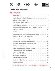
APPLICATION EXAMPLE (SV BIAS)<br />
Series SR73A & SR74A<br />
Temperature sensor<br />
Set value for target temperature (SV)<br />
SR73A<br />
controller<br />
Timer<br />
T<br />
Plant culture tank<br />
23˚C<br />
SV bias (SB) –5˚C<br />
18˚C<br />
Bias operation<br />
signal<br />
ON<br />
OFF Day Night Day Night<br />
Heater<br />
SR73A AND SR74A<br />
•SR73A<br />
External Dimensions<br />
Panel Cutout<br />
110<br />
130 min.<br />
PV<br />
SV<br />
96<br />
˚C<br />
10<br />
100<br />
92 +0.8<br />
0<br />
92 +0.8<br />
0<br />
130 min.<br />
OUT AT AH AH/HB<br />
96<br />
Unit: mm<br />
ENT<br />
SR73A<br />
<strong>SHIMADEN</strong><br />
•SR74A<br />
110<br />
(48 x N-3) +1.0<br />
0<br />
96<br />
10<br />
100<br />
PV<br />
92 +0.8<br />
0<br />
45 +0.6<br />
0<br />
SV<br />
ßC<br />
OUT AT AN AH/HB<br />
ENT<br />
96<br />
130 min.<br />
When instruments are installed<br />
in colse contact with each other<br />
sideways,<br />
N=the number of instruments.<br />
SR74A<br />
<strong>SHIMADEN</strong><br />
Unit: mm<br />
Terminal arrangement<br />
•SR73A<br />
422A 485<br />
SG SG 1<br />
21<br />
31 11 L<br />
SB<br />
Power<br />
SD+ +<br />
2<br />
22<br />
32 12 N<br />
SD– –<br />
3<br />
23<br />
33 13<br />
CT<br />
RD+<br />
4<br />
24<br />
34 14 COM+<br />
CONTROL<br />
RD–<br />
5<br />
25<br />
35 15 NO –<br />
OUTPUT<br />
6<br />
26<br />
36 16 NC<br />
~<br />
Terminal arrangement<br />
•SR74A<br />
422A 485<br />
SG SG 1<br />
11 L<br />
21 22<br />
Power<br />
SD+ +<br />
2<br />
12 N<br />
SB<br />
SD– –<br />
3<br />
13<br />
RD+<br />
4<br />
14 COM+<br />
CONTROL<br />
RD–<br />
5<br />
15 NO –<br />
OUTPUT<br />
6<br />
16 NC<br />
~<br />
IN PUT RTD<br />
+A<br />
TC•mV<br />
V•mA<br />
–B<br />
B<br />
7<br />
27<br />
37 17<br />
8<br />
28<br />
38 18<br />
9<br />
29<br />
39 19<br />
10 30<br />
40 20<br />
COM<br />
AH<br />
AL/HB<br />
ALARM<br />
OUTPUT<br />
IN PUT RTD<br />
+A<br />
TC•mV<br />
V•mA<br />
–B<br />
B<br />
7<br />
17<br />
8<br />
18<br />
CT<br />
9<br />
19<br />
23 24<br />
10 20<br />
COM<br />
AH<br />
AL/HR<br />
ALARM<br />
OUTPUT
MEASURING RANGE CODES<br />
Series SR73A & SR74A<br />
Multi input<br />
Voltage<br />
V<br />
Current<br />
mA<br />
lnput type Code<br />
Measuring<br />
Measuring<br />
Range<br />
Code<br />
Range<br />
*1B 01 0~ 1800˚C 12 0~ 3300˚F<br />
R 02 0~ 1700˚C 13 0~ 3100˚F<br />
S 03 0~ 1700˚C 14 0~ 3100˚F<br />
K 04 –100~ 400˚C 15 –150~ 750˚F<br />
K 05 0~ 1200˚C 16 0~ 2200˚F<br />
E 06 0~ 700˚C 17 0~ 1300˚˚F<br />
J 07 0~ 600˚C 18 0~ 1100˚F<br />
T 08 –199.9~ 200.0˚C 19 –300~ 400˚F<br />
N 09 0~ 1300˚C 20 0~ 2300˚F<br />
*2U 10 –199.9~ 200.0˚C 21 –300~ 400˚F<br />
*2L 11 0~ 600˚C 22 0~ 1100˚F<br />
31 –200~ 600˚C 39 –300~ 1100˚F<br />
Pt100<br />
32 –100.0~ 100.0˚C 40 –150.0~ 200.0˚F<br />
33 –50.0~ 50.0˚C 41 –50.0~ 120.0˚F<br />
34 0.0~ 200.0˚C 42 0~ 400˚F<br />
35 –200~ 600˚C 43 –300~ 1100˚F<br />
JPt100<br />
36 –100.0~ 100.0˚C 44 –150.0~200.0˚F<br />
37 –50.0~ 50.0˚C 45 –50.0~120.0˚F<br />
38 0.0~ 200.0˚C 46 0~ 400˚F<br />
0~ 10 71<br />
10~ 50 72<br />
0~100 73<br />
Thermocouple<br />
R. T. D.<br />
Voltage<br />
mV<br />
0~ 1 81<br />
0~ 5 82<br />
0~ 10 83<br />
4~ 20 95<br />
lnitial value : 0.0~100.0<br />
Conditions of scaling<br />
Scaling setting range :<br />
–1999~9999,<br />
Span :100~5000 counts<br />
Position of decimal point:<br />
No decimal point,the<br />
first,second and third<br />
decimal places<br />
Thermocouple<br />
B, R, S, K, E, J, T, N : JIS/ANSI/IEC<br />
R. T. D.<br />
Pt100 : Present JIS/IEC<br />
JPt100 : Old JIS<br />
*1 Thermocouple B : Accuracy not<br />
guaranteed for temperatures<br />
below 400˚C(750˚F)<br />
*2 Thermocouple U, L·DIN43710<br />
TERMINAL COVER (AVAILABLE<br />
SR73A<br />
SR74A<br />
Model<br />
SR5301-9<br />
SR5401-7<br />
Material / Appearance: PVC / transparent<br />
Thickness: 1mm<br />
Mounting: 2+B tight pan-head screws<br />
M2.336mm<br />
Warning<br />
• The SR73A & SR74A series is designed for the control of temperature, humidity and other physical values of general<br />
industrial equipment. (It is not to be used for any purpose which regulates the prevention of serious effects on human life or<br />
safety.)<br />
Caution<br />
• If the possibility of loss or damage to your system or property as a result of failure of any part of the process exists,<br />
proper safety measures must be made before the instrument is put into use so as to prevent the occurrence of trouble.