RF12 Universal ISM Band FSK Transceiver
RF12 Universal ISM Band FSK Transceiver
RF12 Universal ISM Band FSK Transceiver

Create successful ePaper yourself
Turn your PDF publications into a flip-book with our unique Google optimized e-Paper software.
<strong>RF12</strong><br />
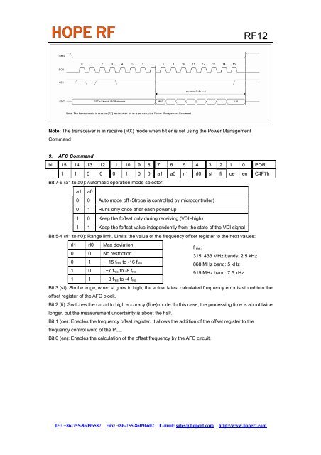
Note: The transceiver is in receive (RX) mode when bit er is set using the Power Management<br />
Command<br />
9. AFC Command<br />
bit 15 14 13 12 11 10 9 8 7 6 5 4 3 2 1 0 POR<br />
1 1 0 0 0 1 0 0 a1 a0 rl1 rl0 st fi oe en C4F7h<br />
Bit 7-6 (a1 to a0): Automatic operation mode selector:<br />
a1 a0<br />
0 0 Auto mode off (Strobe is controlled by microcontroller)<br />
0 1 Runs only once after each power-up<br />
1 0 Keep the foffset only during receiving (VDI=high)<br />
1 1 Keep the foffset value independently from the state of the VDI signal<br />
Bit 5-4 (rl1 to rl0): Range limit. Limits the value of the frequency offset register to the next values:<br />
rl1 rl0 Max deviation<br />
0 0 No restriction<br />
0 1 +15 f res to -16 f res<br />
1 0 +7 f res to -8 f res<br />
1 1 +3 f res to -4 f res<br />
f res:<br />
315, 433 MHz bands: 2.5 kHz<br />
868 MHz band: 5 kHz<br />
915 MHz band: 7.5 kHz<br />
Bit 3 (st): Strobe edge, when st goes to high, the actual latest calculated frequency error is stored into the<br />
offset register of the AFC block.<br />
Bit 2 (fi): Switches the circuit to high accuracy (fine) mode. In this case, the processing time is about twice<br />
longer, but the measurement uncertainty is about the half.<br />
Bit 1 (oe): Enables the frequency offset register. It allows the addition of the offset register to the<br />
frequency control word of the PLL.<br />
Bit 0 (en): Enables the calculation of the offset frequency by the AFC circuit.<br />
Tel: +86-755-86096587 Fax: +86-755-86096602 E-mail: sales@hoperf.com http://www.hoperf.com