RF12 Universal ISM Band FSK Transceiver
RF12 Universal ISM Band FSK Transceiver
RF12 Universal ISM Band FSK Transceiver

You also want an ePaper? Increase the reach of your titles
YUMPU automatically turns print PDFs into web optimized ePapers that Google loves.
<strong>RF12</strong><br />
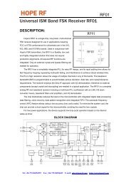
Note:<br />
Lock bit is high when the AFC loop is locked, f same bit indicates when two subsequent measuring<br />
results are the same, toggle bit changes state in every measurement cycle.<br />
In automatic operation mode (no strobe signal is needed from the microcontroller to update the<br />
output offset register) the AFC circuit is automatically enabled when the VDI indicates potential incoming<br />
signal during the whole measurement cycle and the circuit measures the same result in two subsequent<br />
cycles.<br />
There are three operation modes, example from the possible application:<br />
1, (a1=0, a0=1) The circuit measures the frequency offset only once after power up. In this way<br />
extended TX-RX maximum distance can be achieved.<br />
Possible application:<br />
In the final application, when the user inserts the battery, the circuit measures and compensates for<br />
the frequency offset caused by the crystal tolerances. This method allows for the use of a cheaper quartz<br />
in the application and provides protection against tracking an interferer.<br />
2a, (a1=1, a0=0) The circuit automatically measures the frequency offset during an initial effective<br />
low data rate pattern –easier to receive (i.e.: 00110011) of the package and changes the receiving<br />
frequency accordingly. The further part of the package can be received by the corrected frequency<br />
settings.<br />
2b, (a1=1, a0=0) The transmitter must transmit the first part of the packet with a step higher<br />
deviation and later there is a possibility to reduce it.<br />
In both cases (2a and 2b), when the VDI indicates poor receiving conditions (VDI goes low), the<br />
output register is automatically cleared. Use these settings when receiving signals from different<br />
transmitters transmitting in the same nominal frequencies.<br />
3, (a1=1, a0=1) It’s the same as 2a and 2b modes, but suggested to use when a receiver operates<br />
with only one transmitter. After a complete measuring cycle, the measured value is kept independently of<br />
the state of the VDI signal.<br />
Tel: +86-755-86096587 Fax: +86-755-86096602 E-mail: sales@hoperf.com http://www.hoperf.com