RF12 Universal ISM Band FSK Transceiver
RF12 Universal ISM Band FSK Transceiver
RF12 Universal ISM Band FSK Transceiver

You also want an ePaper? Increase the reach of your titles
YUMPU automatically turns print PDFs into web optimized ePapers that Google loves.
<strong>RF12</strong><br />
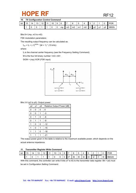
10. TX Configuration Control Command<br />
bit 15 14 13 12 11 10 9 8 7 6 5 4 3 2 1 0 POR<br />
1 0 0 1 1 0 0 mp m3 m2 m1 m0 0 p2 p1 p0 9800h<br />
Bits 8-4 (mp, m3 to m0):<br />
<strong>FSK</strong> modulation parameters:<br />
The resulting output frequency can be calculated as:<br />
f out = f 0 + (-1) SIGN * (M + 1) * (15 kHz)<br />
where:<br />
f 0 is the channel center frequency (see the Frequency Setting Command)<br />
M is the four bit binary number <br />
SIGN = (mp) XOR (<strong>FSK</strong> input)<br />
Bits 2-0 (p2 to p0): Output power:<br />
p2 p1 p0 Relative Output Power [dB]<br />
0 0 0 0<br />
0 0 1 -3<br />
0 1 0 -6<br />
0 1 1 -9<br />
1 0 0 -12<br />
1 0 1 -15<br />
1 1 0 -18<br />
1 1 1 -21<br />
The output power given in the table is relative to the maximum available power, which depends on the<br />
actual antenna impedance.<br />
11. Transmitter Register Write Command<br />
bit 15 14 13 12 11 10 9 8 7 6 5 4 3 2 1 0 POR<br />
1 0 1 1 1 0 0 0 t7 t6 t5 t4 t3 t2 t1 t0 B8AAh<br />
With this command, the controller can write 8 bits (t7 to t0) to the transmitter data register. Bit 7 (el) must<br />
be set in Configuration Setting Command.<br />
Tel: +86-755-86096587 Fax: +86-755-86096602 E-mail: sales@hoperf.com http://www.hoperf.com