RF12 Universal ISM Band FSK Transceiver
RF12 Universal ISM Band FSK Transceiver
RF12 Universal ISM Band FSK Transceiver

Create successful ePaper yourself
Turn your PDF publications into a flip-book with our unique Google optimized e-Paper software.
<strong>RF12</strong><br />
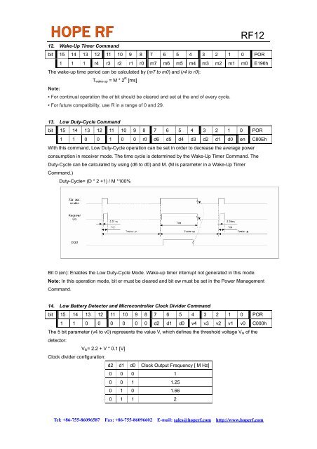
12. Wake-Up Timer Command<br />
bit 15 14 13 12 11 10 9 8 7 6 5 4 3 2 1 0 POR<br />
1 1 1 r4 r3 r2 r1 r0 m7 m6 m5 m4 m3 m2 m1 m0 E196h<br />
The wake-up time period can be calculated by (m7 to m0) and (r4 to r0):<br />
T wake-up = M * 2 R [ms]<br />
Note:<br />
• For continual operation the et bit should be cleared and set at the end of every cycle.<br />
• For future compatibility, use R in a range of 0 and 29.<br />
13. Low Duty-Cycle Command<br />
bit 15 14 13 12 11 10 9 8 7 6 5 4 3 2 1 0 POR<br />
1 1 0 0 1 0 0 r0 d6 d5 d4 d3 d2 d1 d0 en C80Eh<br />
With this command, Low Duty-Cycle operation can be set in order to decrease the average power<br />
consumption in receiver mode. The time cycle is determined by the Wake-Up Timer Command. The<br />
Duty-Cycle can be calculated by using (d6 to d0) and M. (M is parameter in a Wake-Up Timer<br />
Command.)<br />
Duty-Cycle= (D * 2 +1) / M *100%<br />
Bit 0 (en): Enables the Low Duty-Cycle Mode. Wake-up timer interrupt not generated in this mode.<br />
Note: In this operation mode, bit er must be cleared and bit ew must be set in the Power Management<br />
Command.<br />
14. Low Battery Detector and Microcontroller Clock Divider Command<br />
bit 15 14 13 12 11 10 9 8 7 6 5 4 3 2 1 0 POR<br />
1 1 0 0 0 0 0 0 d2 d1 d0 v4 v3 v2 v1 v0 C000h<br />
The 5 bit parameter (v4 to v0) represents the value V, which defines the threshold voltage V lb of the<br />
detector:<br />
V lb = 2.2 + V * 0.1 [V]<br />
Clock divider configuration:<br />
d2 d1 d0 Clock Output Frequency [ M Hz]<br />
0 0 0 1<br />
0 0 1 1.25<br />
0 1 0 1.66<br />
0 1 1 2<br />
Tel: +86-755-86096587 Fax: +86-755-86096602 E-mail: sales@hoperf.com http://www.hoperf.com