Bios Integrator 110 User Manual - Mesa Labs
Bios Integrator 110 User Manual - Mesa Labs
Bios Integrator 110 User Manual - Mesa Labs

Create successful ePaper yourself
Turn your PDF publications into a flip-book with our unique Google optimized e-Paper software.
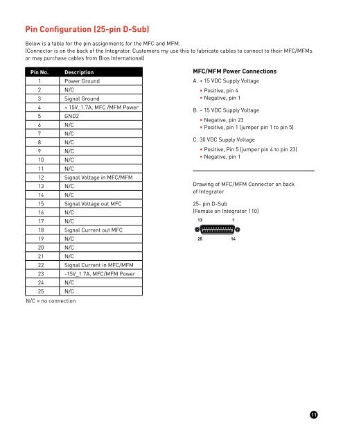
Pin Configuration (25-pin D-Sub)Below is a table for the pin assignments for the MFC and MFM.(Connector is on the back of the <strong>Integrator</strong>. Customers my use this to fabricate cables to connect to their MFC/MFMsor may purchase cables from <strong>Bios</strong> International)Pin No. Description1 Power Ground2 N/C3 Signal Ground4 + 15V_1.7A, MFC /MFM Power5 GND26 N/C7 N/C8 N/C9 N/C10 N/C11 N/C12 Signal Voltage in MFC/MFM13 N/C14 N/C15 Signal Voltage out MFC16 N/C17 N/C18 Signal Current out MFC19 N/C20 N/C21 N/C22 Signal Current in MFC/MFM23 -15V_1.7A, MFC/MFM Power24 N/C25 N/CN/C = no connectionMFC/MFM Power ConnectionsA. + 15 VDC Supply Voltage• Positive, pin 4• Negative, pin 1B. – 15 VDC Supply Voltage• Negative, pin 23• Positive, pin 1 (jumper pin 1 to pin 5)C. 30 VDC Supply Voltage• Positive, Pin 5 (jumper pin 4 to pin 23)• Negative, pin 1Drawing of MFC/MFM Connector on backof <strong>Integrator</strong>25- pin D-Sub(Female on <strong>Integrator</strong> <strong>110</strong>)132511411