Bios Integrator 110 User Manual - Mesa Labs
Bios Integrator 110 User Manual - Mesa Labs
Bios Integrator 110 User Manual - Mesa Labs

You also want an ePaper? Increase the reach of your titles
YUMPU automatically turns print PDFs into web optimized ePapers that Google loves.
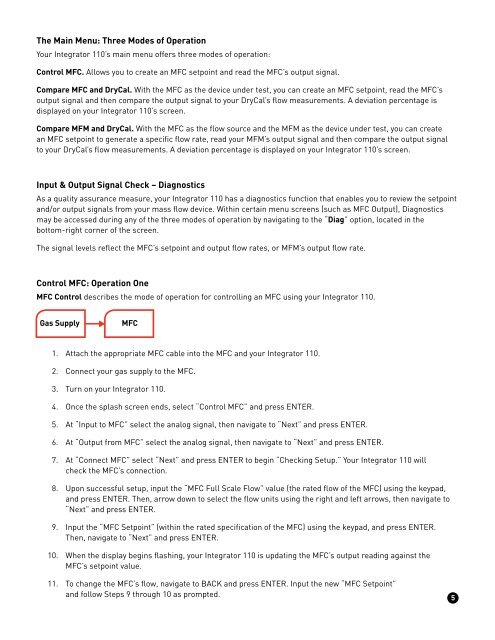
The Main Menu: Three Modes of OperationYour <strong>Integrator</strong> <strong>110</strong>’s main menu offers three modes of operation:Control MFC. Allows you to create an MFC setpoint and read the MFC’s output signal.Compare MFC and DryCal. With the MFC as the device under test, you can create an MFC setpoint, read the MFC’soutput signal and then compare the output signal to your DryCal’s flow measurements. A deviation percentage isdisplayed on your <strong>Integrator</strong> <strong>110</strong>’s screen.Compare MFM and DryCal. With the MFC as the flow source and the MFM as the device under test, you can createan MFC setpoint to generate a specific flow rate, read your MFM’s output signal and then compare the output signalto your DryCal’s flow measurements. A deviation percentage is displayed on your <strong>Integrator</strong> <strong>110</strong>’s screen.Input & Output Signal Check – DiagnosticsAs a quality assurance measure, your <strong>Integrator</strong> <strong>110</strong> has a diagnostics function that enables you to review the setpointand/or output signals from your mass flow device. Within certain menu screens (such as MFC Output), Diagnosticsmay be accessed during any of the three modes of operation by navigating to the “Diag” option, located in thebottom-right corner of the screen.The signal levels reflect the MFC’s setpoint and output flow rates, or MFM’s output flow rate.Control MFC: Operation OneMFC Control describes the mode of operation for controlling an MFC using your <strong>Integrator</strong> <strong>110</strong>.Gas SupplyMFC1. Attach the appropriate MFC cable into the MFC and your <strong>Integrator</strong> <strong>110</strong>.2. Connect your gas supply to the MFC.3. Turn on your <strong>Integrator</strong> <strong>110</strong>.4. Once the splash screen ends, select “Control MFC” and press ENTER.5. At “Input to MFC” select the analog signal, then navigate to “Next” and press ENTER.6. At “Output from MFC” select the analog signal, then navigate to “Next” and press ENTER.7. At “Connect MFC” select “Next” and press ENTER to begin “Checking Setup.” Your <strong>Integrator</strong> <strong>110</strong> willcheck the MFC’s connection.8. Upon successful setup, input the “MFC Full Scale Flow” value (the rated flow of the MFC) using the keypad,and press ENTER. Then, arrow down to select the flow units using the right and left arrows, then navigate to“Next” and press ENTER.9. Input the “MFC Setpoint” (within the rated specification of the MFC) using the keypad, and press ENTER.Then, navigate to “Next” and press ENTER.10. When the display begins flashing, your <strong>Integrator</strong> <strong>110</strong> is updating the MFC’s output reading against theMFC’s setpoint value.11. To change the MFC’s flow, navigate to BACK and press ENTER. Input the new “MFC Setpoint”and follow Steps 9 through 10 as prompted.5