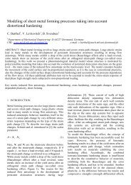
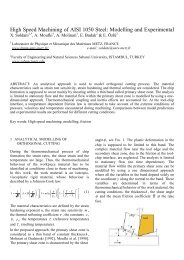
eJ / 2βD pD mr pJ / 2PunchFig. 2.Geometrical parameters characteristic of blanking.The main conclusions of <strong>the</strong>se studies show that <strong>the</strong>size of burr <strong>de</strong>pends mainly on <strong>the</strong> blankingclearance, <strong>the</strong> wear condition of <strong>the</strong> tool edge andproperties of <strong>the</strong> cutting materials and <strong>the</strong> toolmateriel. According to <strong>the</strong> studies carried out in [1]and [2], it appears that <strong>the</strong> wear promotes <strong>the</strong>appearance of burr and that <strong>the</strong> increase in <strong>the</strong>blanking clearance results in an increase in <strong>the</strong>fracture angle of <strong>the</strong> shear zone and <strong>the</strong> height of <strong>the</strong>burr. This is confirmed also in [3] and [4]. Withregards to <strong>the</strong> properties of blanking materials,Gréban in [5] says that <strong>the</strong> composition of cuttingalloys has a strong influence on <strong>the</strong> quantity of burrsthat is created during <strong>the</strong> blanking operation.However, <strong>the</strong> works are more on <strong>the</strong> <strong>the</strong>oreticalstudy of <strong>the</strong> conditions of burr appearance, than onan experimental metrology on <strong>the</strong> burr amount.αr mBlank-hol<strong>de</strong>rSheet metalDie3.1 MetrologyWe can see that in literature, <strong>the</strong>re are many ways ofmeasuring burr, but fundamentally based on a<strong>de</strong>structive test of blanking pieces and <strong>the</strong>refore ofmetrology in a few positions of <strong>the</strong> cutting edge.O<strong>the</strong>r methods that have been proposed formetrology burr heights were <strong>the</strong> non-contact ortactile optical profilometry [7], or <strong>the</strong> visionmetrology [8] of <strong>the</strong> cutting edge, which is aimed atpieces with straight faces. The latter allows <strong>the</strong>naccess to <strong>the</strong> profile heights of burr over a length ofcut board of 4mm. Ano<strong>the</strong>r example is ameasurement using <strong>the</strong> shadow of burr or a moretraditional measure, <strong>the</strong> mechanical profilometry.3.2 Crushed burrIn <strong>the</strong> case of progressive blanking, complexgeometry of <strong>the</strong> parts is produced by several pressstrokes, which has <strong>the</strong> effect of crushing burrs. Thismakes it more difficult to measure <strong>the</strong> height of <strong>the</strong>burr by traditional means.3 METROLOGY OF BURRThe possibility to estimate <strong>the</strong> burr size on <strong>the</strong> blankpieces remains of great importance in <strong>the</strong> blankingindustry, because <strong>the</strong> quality of <strong>the</strong> products is<strong>de</strong>termined with <strong>the</strong> evaluation of <strong>the</strong> level ofacceptable burr on <strong>the</strong> parts. It is possible to study,in <strong>the</strong>ory, <strong>the</strong> emergence of blanking burrs.However, if we wish to verify <strong>the</strong> <strong>the</strong>oreticalpredictions, it is necessary to be able to accuratelyand reliably measure <strong>the</strong> quantity of burrs. Tosummarize, we can return to what might be a<strong>de</strong>finition of <strong>the</strong> burr height, <strong>the</strong> main criterionmentioned here. According to [6], because <strong>the</strong> sheetcan have a residual macroscopic <strong>de</strong>formation during<strong>the</strong> cutting operation, <strong>the</strong> height of burr is <strong>de</strong>fined as"<strong>the</strong> difference between <strong>the</strong> highest point of burr and<strong>the</strong> surface of <strong>the</strong> sheet metal immediately adjacentto <strong>the</strong> burr". This <strong>de</strong>finition seems satisfactory andwill be <strong>the</strong> basis for <strong>de</strong>velopment of our work.Fig. 3. Crushed burr.This has prompted us to seek, in this work, a newmethod more able to give us a precise quantificationof <strong>the</strong> crushed burr. To do this, we sought to <strong>de</strong>fine areference plan around <strong>the</strong> cutting form, because <strong>the</strong>adjacent sheet is distorted.3.3 Establishing a means of measurementIn our approach to <strong>the</strong> burr quantification, we soughtto meet a need, which is to confront <strong>the</strong> <strong>the</strong>oreticalresults with experimental robust measurements.3.3.a Images AcquisitionThe <strong>de</strong>vice used is a microscope Infinitefocus ®
Alicona (Fig.4). It is based on an optical microscopecoupled to a camera. Unlike a confocal microscope,which uses a monochromatic sensor, <strong>the</strong> <strong>de</strong>vice usesa sensor of contrast in color. On <strong>the</strong> whole height,<strong>the</strong> microscope collects images which are <strong>the</strong>nanalysed by <strong>the</strong> software. The latter analyses eachpixel and compares it to its neighbours to see if it isfocused or not. Then, it reconstructs a threedimensionalimage from this focus. From this image,surface-, volume-, surface state- and topographydimensional measurements are possible. Inaccordance with selected lens, <strong>the</strong> image size rangesfrom 2.1x1.6mm ² to 103x83 µm² and resolution inheight from 444nm to 20nm. If <strong>the</strong> sample or area ofinterest is larger than <strong>the</strong> size of capture of <strong>the</strong>selected lens, it is possible to achieve a multi-fieldacquisition through motorized tables. We only needto i<strong>de</strong>ntify <strong>the</strong> entire area to be analysed, and byinterconnection between image fields acquired withrecoveries, we reconstructed a joined-fie image.Profile afterstraighteningProfile beforestraighteningFig. 5 . Profiles on <strong>the</strong> surface of <strong>the</strong> sheet before and afterstraightening .• Secondly, an image processing is performed inor<strong>de</strong>r to extract <strong>the</strong> profiles that we wishvertically from <strong>the</strong> contour of <strong>the</strong> blanked shape(Fig. 6).Blanked ShapeSheet metalProfile beginningProfileFig. 4. The optical <strong>de</strong>vice measurement: InfiniteFocus ®3.3.b MeasurementThe measurement method is <strong>de</strong>veloped within <strong>the</strong>LMS specifically for quantifying <strong>the</strong> burr volume.The originality of this method lies in <strong>the</strong>transformation of <strong>the</strong> blanked shape, (here a circularshape). The main stages of this transformation are:Fig. 6. Example of obtained profile.• Thirdly, <strong>the</strong> profiles are extracted in multiples soas to build a rectangular matrix; each profilebeing <strong>the</strong> average of 100 adjacent profiles.Thereafter, <strong>the</strong> image is adjusted, outsi<strong>de</strong> <strong>the</strong>zone of <strong>the</strong> blun<strong>de</strong>r, with a linear polynomial of<strong>de</strong>gree 2, which assembles all <strong>the</strong> profile (Fig. 7).• First, a straightening of <strong>the</strong> image around <strong>the</strong>blanked shape (hole) is achieved (Fig. 5). This isdone in or<strong>de</strong>r to eliminate any imperfections in<strong>the</strong> image rectitu<strong>de</strong>. The straightening of <strong>the</strong>image (outsi<strong>de</strong> <strong>the</strong> zone of burr) is ma<strong>de</strong> with <strong>the</strong>method of least squares.Fig. 7. Representation of <strong>the</strong> profiles assembling.• Finally, <strong>the</strong> volume is <strong>de</strong>termined only in <strong>the</strong>areas of <strong>the</strong> burr presence on <strong>the</strong> image.