Here - the ESAFORM 2008 Conference - INSA de Lyon
Here - the ESAFORM 2008 Conference - INSA de Lyon
Here - the ESAFORM 2008 Conference - INSA de Lyon

You also want an ePaper? Increase the reach of your titles
YUMPU automatically turns print PDFs into web optimized ePapers that Google loves.
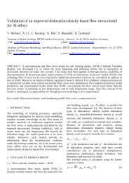
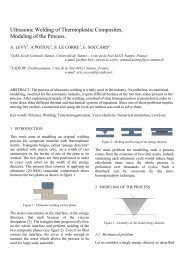
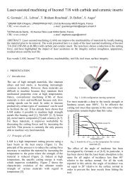
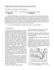
aluminium alloy was AlSi 8 Cu 3 Fe, commonly usedfor die casting. The cooling bath is constituted of adiluted solution (1:80) of a commercial die lubricant.The duration of a typical cycle is of 30s with anactual immersion time of 4s for both <strong>the</strong> aluminiumalloy and cooling baths. All <strong>the</strong> specimens testedwere periodically analyzed to <strong>de</strong>tect <strong>the</strong> formation ofsurface <strong>de</strong>fects by SEM inspection.3 RESULTS AND DISCUSSIONThe reflected light micrograph of <strong>the</strong> ball crater(figure 1) clearly shows <strong>the</strong> multilayer structure of<strong>the</strong> coatings and led to a thickness measurement of2.875±0.074 μm, and clearly shows <strong>the</strong> multilayeredstructure of <strong>the</strong> coatings.Fig. 2. Adhesion Test: appearance of Rockwell in<strong>de</strong>ntations onspecimen A3The coatings <strong>de</strong>posited tested in reciprocatingsliding in term of friction coefficient exhibited asimilar trend, where <strong>the</strong> friction coefficient increasedgradually from 0.55 to 0.65. SEM micrographs of<strong>the</strong> wear scars for coatings A1, A3, B2 and C2(figure 3) shows ploughings marks along <strong>the</strong>direction of sliding, instead for coatings D1 and D3(figure 4) <strong>de</strong>monstrate ploughings marks along <strong>the</strong>direction of sliding plus signs of <strong>de</strong>lamination areas.Fig. 1. Reflected light micrograph of a ball crater on A1The appearance of Rockwell C in<strong>de</strong>ntation onrepresentative coated systems is reported in figure 2.The adhesion was evaluated on <strong>the</strong> base of anobservation of <strong>the</strong> aspects of <strong>the</strong> cracks and of <strong>the</strong>presence of coating <strong>de</strong>tachments around <strong>the</strong>in<strong>de</strong>ntation. The adhesion evaluated through this testcan be consi<strong>de</strong>red good since no <strong>de</strong>tachments of <strong>the</strong>coating along <strong>the</strong> edge of <strong>the</strong> in<strong>de</strong>ntation could berevealed.Fig. 3. SEM micrographic wear scars specimen A1The hardness evaluations for <strong>the</strong> different coatingsas a function of increasing applied weights and, as aconsequence, of increasing in<strong>de</strong>ntation <strong>de</strong>pth. The Acoatings presented <strong>the</strong> highest film hardness (46GPa), <strong>the</strong> D coatings <strong>the</strong> lowest (38 GPa), whereas<strong>the</strong> B and C coatings exhibited an intermediatehardness value (43 GPa).Fig. 4. SEM micrographic wear scars specimen D1