use of digital checking fixtures and scanning techniques for reverse ...
use of digital checking fixtures and scanning techniques for reverse ...
use of digital checking fixtures and scanning techniques for reverse ...

You also want an ePaper? Increase the reach of your titles
YUMPU automatically turns print PDFs into web optimized ePapers that Google loves.
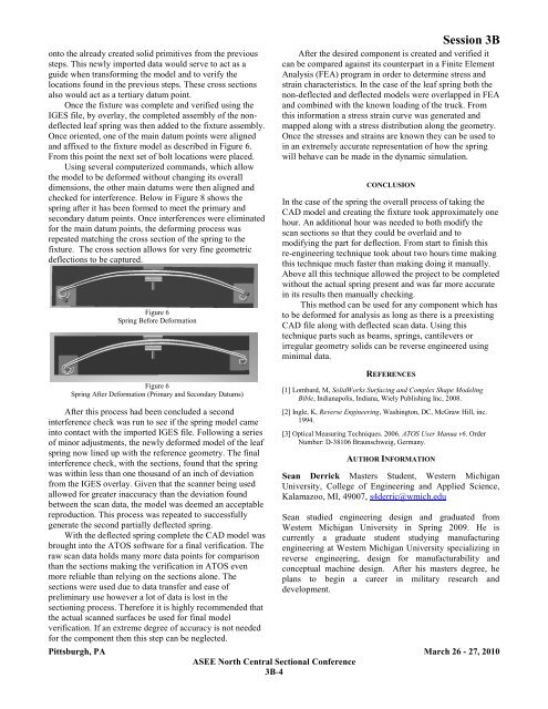
onto the already created solid primitives from the previoussteps. This newly imported data would serve to act as aguide when trans<strong>for</strong>ming the model <strong>and</strong> to verify thelocations found in the previous steps. These cross sectionsalso would act as a tertiary datum point.Once the fixture was complete <strong>and</strong> verified using theIGES file, by overlay, the completed assembly <strong>of</strong> the nondeflectedleaf spring was then added to the fixture assembly.Once oriented, one <strong>of</strong> the main datum points were aligned<strong>and</strong> affixed to the fixture model as described in Figure 6.From this point the next set <strong>of</strong> bolt locations were placed.Using several computerized comm<strong>and</strong>s, which allowthe model to be de<strong>for</strong>med without changing its overalldimensions, the other main datums were then aligned <strong>and</strong>checked <strong>for</strong> interference. Below in Figure 8 shows thespring after it has been <strong>for</strong>med to meet the primary <strong>and</strong>secondary datum points. Once interferences were eliminated<strong>for</strong> the main datum points, the de<strong>for</strong>ming process wasrepeated matching the cross section <strong>of</strong> the spring to thefixture. The cross section allows <strong>for</strong> very fine geometricdeflections to be captured.Figure 6Spring Be<strong>for</strong>e De<strong>for</strong>mationSession 3BAfter the desired component is created <strong>and</strong> verified itcan be compared against its counterpart in a Finite ElementAnalysis (FEA) program in order to determine stress <strong>and</strong>strain characteristics. In the case <strong>of</strong> the leaf spring both thenon-deflected <strong>and</strong> deflected models were overlapped in FEA<strong>and</strong> combined with the known loading <strong>of</strong> the truck. Fromthis in<strong>for</strong>mation a stress strain curve was generated <strong>and</strong>mapped along with a stress distribution along the geometry.Once the stresses <strong>and</strong> strains are known they can be <strong>use</strong>d toin an extremely accurate representation <strong>of</strong> how the springwill behave can be made in the dynamic simulation.CONCLUSIONIn the case <strong>of</strong> the spring the overall process <strong>of</strong> taking theCAD model <strong>and</strong> creating the fixture took approximately onehour. An additional hour was needed to both modify thescan sections so that they could be overlaid <strong>and</strong> tomodifying the part <strong>for</strong> deflection. From start to finish thisre-engineering technique took about two hours time makingthis technique much faster than making doing it manually.Above all this technique allowed the project to be completedwithout the actual spring present <strong>and</strong> was far more accuratein its results then manually <strong>checking</strong>.This method can be <strong>use</strong>d <strong>for</strong> any component which hasto be de<strong>for</strong>med <strong>for</strong> analysis as long as there is a preexistingCAD file along with deflected scan data. Using thistechnique parts such as beams, springs, cantilevers orirregular geometry solids can be <strong>reverse</strong> engineered usingminimal data.Figure 6Spring After De<strong>for</strong>mation (Primary <strong>and</strong> Secondary Datums)After this process had been concluded a secondinterference check was run to see if the spring model cameinto contact with the imported IGES file. Following a series<strong>of</strong> minor adjustments, the newly de<strong>for</strong>med model <strong>of</strong> the leafspring now lined up with the reference geometry. The finalinterference check, with the sections, found that the springwas within less than one thous<strong>and</strong> <strong>of</strong> an inch <strong>of</strong> deviationfrom the IGES overlay. Given that the scanner being <strong>use</strong>dallowed <strong>for</strong> greater inaccuracy than the deviation foundbetween the scan data, the model was deemed an acceptablereproduction. This process was repeated to successfullygenerate the second partially deflected spring.With the deflected spring complete the CAD model wasbrought into the ATOS s<strong>of</strong>tware <strong>for</strong> a final verification. Theraw scan data holds many more data points <strong>for</strong> comparisonthan the sections making the verification in ATOS evenmore reliable than relying on the sections alone. Thesections were <strong>use</strong>d due to data transfer <strong>and</strong> ease <strong>of</strong>preliminary <strong>use</strong> however a lot <strong>of</strong> data is lost in thesectioning process. There<strong>for</strong>e it is highly recommended thatthe actual scanned surfaces be <strong>use</strong>d <strong>for</strong> final modelverification. If an extreme degree <strong>of</strong> accuracy is not needed<strong>for</strong> the component then this step can be neglected.REFERENCES[1] Lombard, M, SolidWorks Surfacing <strong>and</strong> Complex Shape ModelingBible, Indianapolis, Indiana, Wiely Publishing Inc, 2008.[2] Ingle, K, Reverse Engineering, Washington, DC, McGraw Hill, inc.1994.[3] Optical Measuring Techniques. 2006. ATOS User Manua v6. OrderNumber: D-38106 Braunschweig, Germany.AUTHOR INFORMATIONSean Derrick Masters Student, Western MichiganUniversity, College <strong>of</strong> Engineering <strong>and</strong> Applied Science,Kalamazoo, MI, 49007, s4derric@wmich.eduSean studied engineering design <strong>and</strong> graduated fromWestern Michigan University in Spring 2009. He iscurrently a graduate student studying manufacturingengineering at Western Michigan University specializing in<strong>reverse</strong> engineering, design <strong>for</strong> manufacturability <strong>and</strong>conceptual machine design. After his masters degree, heplans to begin a career in military research <strong>and</strong>development.Pittsburgh, PA March 26 - 27, 2010ASEE North Central Sectional Conference3B-4