laboratory experiments on a doubly fed induction generator
laboratory experiments on a doubly fed induction generator
laboratory experiments on a doubly fed induction generator

Create successful ePaper yourself
Turn your PDF publications into a flip-book with our unique Google optimized e-Paper software.
120 fn sync [1]PThis is also known as the synchr<strong>on</strong>ous speed, where f is thesystem frequency in hertz, and P is the number of poles inthe machine. This rotating magnetic field then passes overthe rotor windings, inducing current, I. When this currentflows through the windings, a force is induced <strong>on</strong> the rotorby the Lorentz Law F I B [2]As the rotor approaches synchr<strong>on</strong>ous speed, the inducedvoltage <strong>on</strong> the rotor decreases. However, <strong>on</strong>ce the rotor is atsynchr<strong>on</strong>ous speed there is no induced voltage, thus there isno current through the rotor to yield a magnetic field. Withno rotor magnetic field, the induced torque becomes 0. Ifthe speed of the machine is driven to a speed greater thann sync the machine will behave as a <strong>generator</strong> because there isa reversal in directi<strong>on</strong> of the torque. A typical torque/speedcharacteristic of an inducti<strong>on</strong> machine is shown in Figure 1.Sessi<strong>on</strong> 4DIn a wind turbine applicati<strong>on</strong>, negative slip is desirable sothe machine is in the generating regi<strong>on</strong> of its torque speedcharacteristic. To force the machine into the generatingregi<strong>on</strong>, the rotor frequency may be influenced externally,therefore varying the slip.DFIG Wind Turbine ModelA DFIG wind turbine makes use of a wound-rotor inducti<strong>on</strong><strong>generator</strong> with external voltage <strong>on</strong> the rotor of the machine.In a Closed Loop scheme, the stator coils of the machine arec<strong>on</strong>nected to the grid. In an Open Loop scheme, or selfexcited,the stator coils are c<strong>on</strong>nected to a capacitor bank toprovide the reactive energy needed to propagate the rotatingmagnetic field. The external voltage in this experiment isbeing applied by a Variable Frequency Drive (VFD). Figures2 and 3 are schematic representati<strong>on</strong>s of these two schemes.The purpose of the VFD in the DFIG is to manipulate thefrequency of the rotor voltage to keep the machine in thegenerating regi<strong>on</strong>. The commercial VFD operates <strong>on</strong>ly withthe following fixed, steady-state settings: output frequency,output voltage, and output power factor.Figure 1: A typical torque/speed characteristic of aninducti<strong>on</strong> machineThe voltage induced in the rotor of an inducti<strong>on</strong> motordepends <strong>on</strong> difference in rotati<strong>on</strong>al speed between the statorFigure 2: Closed Loop DFIG c<strong>on</strong>figurati<strong>on</strong> with externalvoltage applied by VFDfield and the rotor field. This difference is used to define theslip speed of the machine. Slip speed is defined asnslip nsync nm[3]where n m is the mechanical shaft speed of the machine. With[3] the slip of the machine can be found bys nnslipsync*100%Using the slip of the machine, the frequency <strong>on</strong> the rotor canbe found usingsf f r [5][4]Figure 3: Open Loop DFIG c<strong>on</strong>figurati<strong>on</strong> with externalvoltage applied by VFDPittsburgh, PA March 26 - 27, 2010ASEE North Central Secti<strong>on</strong>al C<strong>on</strong>ference4D-2
In the open loop c<strong>on</strong>figurati<strong>on</strong>, capacitors are c<strong>on</strong>nected tothe stator of the machine to provide sufficient excitati<strong>on</strong>reactance to produce voltage at the stator terminals. Factorsthat affect the regulati<strong>on</strong> of the generated voltage are themachine magnetizati<strong>on</strong> properties, magnitude of theexcitati<strong>on</strong> capacitance, and the machine‟s resistive circuits.If the excitati<strong>on</strong> capacitance is too small, the <strong>generator</strong> willfail to building up voltage. If it is too large, the machinemay experience voltages higher than its nameplate rating 5 .A disadvantage of a self-excited DFIG c<strong>on</strong>figurati<strong>on</strong> is thatwith properly sized capacitors attached to the stator, thegenerated voltage decreases with an increasing, balanced,three phase load, neglecting the power factor 5 .In a closed loop c<strong>on</strong>figurati<strong>on</strong>, the reactive energy requiredto stabilize the magnetic field is provided by thegrid/frequency c<strong>on</strong>verter.Laboratory ExperimentsWith an external, variable frequency source exciting thewound rotor of the inducti<strong>on</strong> machine, the equivalent circuitof the machine is shown in Figure 4.Sessi<strong>on</strong> 4DWhen the stator is c<strong>on</strong>nected to the grid, the grid imposes itsvoltage and frequency to the stator of the machine, thereforethe rotor current from the VFD is a moderator of active andreactive power between the inducti<strong>on</strong> machine and the grid.In a self-excited DFIG arrangement, it is required that thevoltage be c<strong>on</strong>trolled to maintain the nameplate ratings ofthe machine.E r is a c<strong>on</strong>trol voltage in the self-excited DFIG arrangement.Under system loadEs isjXs isRs isZload[8]Because the DFIG‟s mmf‟s rotati<strong>on</strong>al directi<strong>on</strong> can be in thesame or the opposite directi<strong>on</strong>, the frequency of the stator fora 3 pole machine isfs fm fr[9]where f m is the mechanical shaft frequency. To dem<strong>on</strong>stratea DFIG in the self-excited envir<strong>on</strong>ment, data was acquiredby holding the shaft speed c<strong>on</strong>stant at 3540 rpm and varyingthe frequency of the injected voltage <strong>on</strong> the rotor.Figure 4: The equivalent circuit of the DFIG with an external voltage supplied by the VFD, with loadThe inducti<strong>on</strong> machine stator and rotor voltages are given bythe following steady-state phasor equati<strong>on</strong>sEr Vvfd irRr irjXr [6]Es isjXsisRs[7]The as part of the equivalent circuit, the following machineparameters were measured:Rr 1.2 , Xr . 844, Rs . 4,Xs . 152 ,Figure 5: The <str<strong>on</strong>g>laboratory</str<strong>on</strong>g> experimental equipmentPittsburgh, PA March 26 - 27, 2010ASEE North Central Secti<strong>on</strong>al C<strong>on</strong>ference4D-3
A wye-c<strong>on</strong>figurati<strong>on</strong> of 30 μF capacitors was c<strong>on</strong>nected tothe terminals of the stator.Sessi<strong>on</strong> 4DFigure 6: Laboratory experimental setupFigure 8: Stator voltage with a varied capacitance at ac<strong>on</strong>stant shaft speed.Figure 7: Experimental results of the stator line to linevoltage against the VFD frequency injected into the rotor.The machine speed and capacitance are held c<strong>on</strong>stantFigure 7 shows a plot of the stator terminal voltage againstthe injected rotor frequency, where the frequency injected bythe VFD was varied. The capacitance was held at 30 μFwith the dynamometer speed varied. It was calculated thatthe res<strong>on</strong>ant capacitance of the machine used in the labexperiment at 3600 rpm is 31.4 μF. Capacitance was thenvaried when the shaft speed was held c<strong>on</strong>stant. The datataken is seen in Figure 8.In the open loop system, the electric energy supplied by thesystem can work under its nominal c<strong>on</strong>diti<strong>on</strong>s, and thevoltage magnitude and frequency may be maintained withinthe tolerated limits of the system. Capacitors must bec<strong>on</strong>nected to the stator of the machine to serve as a sourcefor the reactive energy that is required to generate themagnetic field of the machine. With variable capacitance itis possible to maintain a c<strong>on</strong>stant stator voltage in variablewind with a VFD. However, the system is sensitive to theload; and can become unstable. Investigati<strong>on</strong> of a loadedsystem is to be investigated.The next <str<strong>on</strong>g>experiments</str<strong>on</strong>g> are a closed loop DFIG with a gridc<strong>on</strong>necti<strong>on</strong>. The initial step in this simulati<strong>on</strong> is tosynchr<strong>on</strong>ize the machine to the grid, <strong>on</strong>ce the machine is upto its operating speed. Because of stator voltage limits, theequivalent grid power was dropped to 85 VAC 60Hz for theexperiment. Figure 9 is a schematic showing the c<strong>on</strong>necti<strong>on</strong>,with 120V 40W light bulbs in series. These are used to limitcurrents as the stator is synchr<strong>on</strong>ized to the grid. When themachine is not synchr<strong>on</strong>ized with the grid, there is a voltagedrop across the bulbs because the output of the machine‟sstator is not in phase with the grid power. Depending <strong>on</strong> thevector phase difference between the two, the lights flicker atthe difference frequency. When the machine is fullysynchr<strong>on</strong>ized with the grid, the bulbs will go completely out;effectively the terminal voltage <strong>on</strong> the machine matches thatof the grid, resulting in no potential difference across thebulbs. Once this occurs, the switch may be thrown, shortingout the bulbs and matching the stator with the grid. Thisacti<strong>on</strong> simulates a synchroscope for <strong>generator</strong>s.Figure 9: Closed loop simulati<strong>on</strong>, synchr<strong>on</strong>izingthe machine to the gridPittsburgh, PA March 26 - 27, 2010ASEE North Central Secti<strong>on</strong>al C<strong>on</strong>ference4D-4
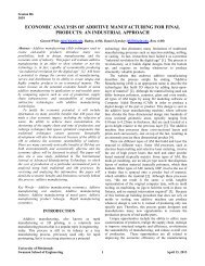
Stator Voltage (Volts)VFD power into the rotor (VA)Figure 10: An oscilloscope probe of the Stator voltage andgrid voltage before synchr<strong>on</strong>izing. Once these waveformsare matched (in phase), the switch may be thrownOnce synchr<strong>on</strong>ized with the VFD activated, steady-statereadings were sampled from attached meters. Figure 11 is aplot of the stator voltage as a functi<strong>on</strong> of machine speed,with f m + f vfd = 60 Hz. The stator voltage remained steady asthe Shaft speed varied.Figure 11: The Stator voltage vs Machine Speedf m + f vfd = 60 HzFigure 11 shows the stator voltage vs. machine speed. Notethat the stator voltage remains nearly c<strong>on</strong>stant over thevarying speed of the rotor. This is important in verifyingnegligible stator voltage oscillati<strong>on</strong>s over the rotor speeds asit synchr<strong>on</strong>izes with the frequency of the grid. Observe thatthe machine speed in the graph centers <strong>on</strong> the nominal speedof 3600 rpm. 3600 rpm is the shaft speed of the machineduring exact synchr<strong>on</strong>izati<strong>on</strong> with the grid. Equati<strong>on</strong> [1]illustrates this relati<strong>on</strong>ship. Figure 12, shows that the statorvoltage remains relatively c<strong>on</strong>stant as the real power ischanged <strong>on</strong> the VFD by adjusting the power factor. Figure13 shows a similar plot of the VFD power supplied to therotor against the stator power, with the power factor varied.Figure 14 shows a plot of the stator voltage against reactivepower <strong>on</strong> the machine‟s stator and Figure 15 shows a plot ofthe stator voltage as a functi<strong>on</strong> of power factor and Figure 16is a plot of the stator voltage against the rotor frequency.Sessi<strong>on</strong> 4DNote the Stator Voltage scaling for the plots in Figure 14 andFigure 16.Stator Voltage Vs. Stator Real Power as VFD Power Factor VariesPittsburgh, PA March 26 - 27, 2010ASEE North Central Secti<strong>on</strong>al C<strong>on</strong>ference4D-51009080706050403020100pf=.3pf=.5pf=.4pf=.6pf=.7pf=.80 20 40 60 80 100 120 140Stator Power (Watts)pf=.9pf=1Figure 12: The Stator voltage vs Stator Real Power deliveredto the „Grid‟. Machine speed is kept c<strong>on</strong>stant at 3600 RPM,the critical point <strong>on</strong> the torque speed characteristic, within areas<strong>on</strong>able tolerance. Power factor of the VFD is marked foreach point.1301201101009080706050403020100Power Supplied to the rotor by the VFD vs Stator Real Powerdelivered to the 'Grid'pf=.5pf=.4pf=.6pf=.9pf=.3pf=.7pf=.80 20 40 60 80 100 120 140Stator Power (Watts)pf=1Figure 13: Power Supplied to the rotor by the VFD vs StatorReal Power delivered to the „Grid‟. Machine speed is keptc<strong>on</strong>stant at 3600 RPM, the critical point <strong>on</strong> the torque speedcharacteristic, within a reas<strong>on</strong>able tolerance. Power factorof the VFD is marked for each point.Figure 14: The Stator voltage vs Stator ReactivePower Delivered to the „Grid‟
Sessi<strong>on</strong> 4Dparameters to c<strong>on</strong>trol stator output <strong>on</strong> a DFIG. The DFIGmay be <strong>fed</strong> and c<strong>on</strong>trolled from the rotor with a VFD, inboth self-excited and grid c<strong>on</strong>nected envir<strong>on</strong>ments. To gainpeak efficiency in the generating system, the scalarinput provided by the VFD adapted the rotor characteristicsin such a way that voltage was maintained <strong>on</strong> the generatingend. The simulati<strong>on</strong> suggests interesting and attractiveperformances of the DFIG in an experimental envir<strong>on</strong>ment.AcknowledgmentFigure 15: The Stator voltage vs VFD PowerFactorFigure 16: Sampled Stator Voltage vs SampledVFD rotor frequencyAnalysisSuccessively, we can show that the stator voltage can bemaintained by injecting the rotor circuit with a VFD output.Note that increasing the rotor speed produces transients inthe voltage of the stator. We can also say that by varying thepower factor, which effectively changes the magnitude ofthe real and reactive power comp<strong>on</strong>ents, we can stillmaintain a c<strong>on</strong>stant stator voltage; however, the statorcurrent will compensate accordingly.By inspecting Figure 13 it is apparent that the net power intothe DFIG is negative for stator output of less than 110W.Once the stator output exceeds 110 watts the power appliedto the rotor by the VFD is less than the output power, and anet positive power is delivered to the grid. In other words,the system will not deliver power to the grid until inputpower from the wind turbine exceeds 110W.C<strong>on</strong>clusi<strong>on</strong>The simulati<strong>on</strong> results from the proposed models show thecapabilities of the DFIG operating in a closed loop and openloop envir<strong>on</strong>ment. The DFIG was initially simulated byinjecting the rotor in an open-loop, self-excited envir<strong>on</strong>ment,followed by simulati<strong>on</strong> in the closed loop arrangement. Thislab simulati<strong>on</strong> suggests an aspect of regulati<strong>on</strong> of rotorSpecial thanks to Dr. George Kusic for his mentoring,advice, and c<strong>on</strong>tributi<strong>on</strong> to the lab simulati<strong>on</strong>.Reference[1] U.S. Department of Energy, 20% Wind Energy by2030: Increasing Wind Energy’s C<strong>on</strong>tributi<strong>on</strong> to U.S.Electricity supply,. Washingt<strong>on</strong> D.C.: U.S. Department ofEnergy, July 2008, p. 1,6.[2] Henrik Stiesdal, “The Wind Turbine, Comp<strong>on</strong>ents andOperati<strong>on</strong>.” Wind Missi<strong>on</strong> , Autumn 1999, p. 13 [Online].Available:http://www.windmissi<strong>on</strong>.dk/workshop/B<strong>on</strong>usTurbine.pdf, [Accessed: December 2009],.[3] Hans Rostoen, Tore M. Undeland, Terje Gjengedal,“Doubly Fed Inducti<strong>on</strong> Generator in a Wind Turbine,”IEEE Norway Secti<strong>on</strong>, p.2, 2002.[4] S. Chapman, Electric Machinery Fundamentals. NewYork:Mc Graw-Hill, 2005, p. 384-387.[5] K.A Nigim, M.A. Kazerani, and M.A Salama,“Identifying machine parameters influencing the operati<strong>on</strong>of the self-excited inducti<strong>on</strong> <strong>generator</strong>,” Elsevier PublishingCompany Inc, 2003, p. 2.[6] Said Drid, Mohhamad-Said Nait-Said, AbdesslamMakouf, Mohamed Tadjine, “Doubly Fed Inducti<strong>on</strong>Generator Modeling and Scalar C<strong>on</strong>troller for Supplying anIsolated side” Journal of Electrical Systems, vol 2, no. 2, pp.103-115, 2006.Appendix AEat<strong>on</strong> VFD SVX9000 AF drive parameters- V1-3~208-240V 50/60Hz I1- 31A, Output V2 3~0-V1 0-320Hz, I225/31A, P2 7.5CT/10VTHampden ULM Model 120 parameters- Universal Machine:1.5-2 KVA, 208/120V 3 phase 60 Hz. 3400-3600 RPM inAC modes. Stator, 24 slots wound with 12 coil single layerwinding, coil pitch 1-12. Measured circuit per phaseequivalents: Rs=.4 Ohms, Ls=14.07 mH, Rr=1.0 Ohms,Lr=2.55mH.Pittsburgh, PA March 26 - 27, 2010ASEE North Central Secti<strong>on</strong>al C<strong>on</strong>ference4D-6