design and construction of mobile surveillance robot
design and construction of mobile surveillance robot
design and construction of mobile surveillance robot

Create successful ePaper yourself
Turn your PDF publications into a flip-book with our unique Google optimized e-Paper software.
ALTERNATIVE DESIGNSSession 4CThere were three different <strong>design</strong>s considered for use: ahanging weight <strong>design</strong> [1], a “hamster ball” driven<strong>design</strong>[2], <strong>and</strong> a dual-tread <strong>design</strong>[3]. The capabilities <strong>and</strong>requirements were considered along with several othercriteria when generating these <strong>design</strong> possibilities.The hanging weight <strong>design</strong> consisted <strong>of</strong> a central shaftwith a carriage hanging from the shaft as displayed in Figure2. The carriage would have the ability to rotate around theshaft which would allow for movement forward <strong>and</strong>backwards. The carriage would also have a small weightinside which would shift side to side to allow the sphere totilt from side to side while moving forward or backward, <strong>and</strong>in so doing provide a turning capability.FIGURE 3HAMSTER BALL DRIVEN DESIGNThe dual-tread <strong>design</strong> would contain two wheels thathave the ability to turn in opposite directions to allow for azero turn radius. The <strong>design</strong> would not be perfectlyspherical, but would still retain the benefits <strong>of</strong> a spherical<strong>design</strong>. A model <strong>of</strong> the dual-tread <strong>design</strong> is displayed inFigure 4.FIGURE 2HANGING WEIGHT DESIGNThe “hamster ball” <strong>design</strong> would operate similar to howa hamster is able to move around in a plastic ball. A <strong>robot</strong>would be contained within a clear plastic sphere withcontrollable wheel(s) at the bottom that roll along the inside<strong>of</strong> the sphere. The wheel(s) would be able to rotate so thatthe sphere could travel in any direction. It would alsocontain stabilization arms that would keep the <strong>robot</strong>centered, the wheel(s) in contact with the sphere, <strong>and</strong> wouldalso protect the components inside the <strong>robot</strong> if the spherewere to suffer a sudden impact. A sketch for the “hamsterball” <strong>design</strong> is displayed in Figure 3.FIGURE 4DUAL-TREAD DESIGNAll three <strong>of</strong> these <strong>design</strong>s were evaluated using adecision matrix that included several <strong>design</strong> criteriaimportant to the project. The results can be seen in Table 1.Pittsburgh, PA March 26 - 27, 2010ASEE North Central Sectional Conference4C-2
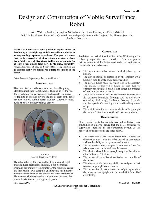
Session 4CTABLE 1DECISION MATRIXCriteriaWeightHanging Carriage Hamster Ball Dual-Tread SphereScore Total Score Total Score TotalStability 25 0.0 0.0 0.5 12.5 1.0 25.0Cost 10 1.0 10.0 0.3 3.3 0.0 0.0Durability 8 0.5 4.0 0.0 0.0 1.0 8.0Power Use 6 1.0 6.0 0.0 0.0 0.5 3.0Feasibility 10 1.0 10.0 0.0 0.0 1.0 10.0Mobility 15 0.0 0.0 0.8 11.3 1.0 15.0Ease <strong>of</strong> Assembly 8 1.0 8.0 0.3 2.7 0.0 0.0Size 5 0.0 0.0 0.7 3.3 1.0 5.0Complexity 5 1.0 5.0 0.0 0.0 0.3 1.7Clarity 8 0.3 2.7 1.0 8.0 0.0 0.0Total 100 45.7 41.1 67.7The <strong>design</strong> that was selected based on the specifiedcriteria was the dual-tread <strong>design</strong>. It was determined that thedual-tread model would be the most stable <strong>and</strong> the most<strong>mobile</strong> due to its wheeled <strong>design</strong>. It should also be easier toinsert equipment inside <strong>of</strong> the dual-tread <strong>design</strong>, allowing fora smaller size which will benefit the mobility <strong>of</strong> the <strong>robot</strong>both in-use <strong>and</strong> for transportation.PROPOSED SYSTEM DESIGNThe <strong>design</strong> chosen to fulfill the requirements is a dual-tread<strong>robot</strong> with a capsule shape as shown in Figure 5.The middle cylindrical-section <strong>of</strong> the <strong>robot</strong> is stationarywhile the two wheels are domed on the outside <strong>and</strong> arecontrolled separately, allowing for a zero-turn radius. Themechanical, controls, data acquisition, <strong>and</strong> powersubsystems are contained within the middle section <strong>of</strong> the<strong>robot</strong>.The elements <strong>of</strong> the subsystems are mounted in such away that the center <strong>of</strong> gravity is well below the geometriccenter <strong>of</strong> the <strong>robot</strong>. The camera <strong>and</strong> transmitters are mountedcloser to the center <strong>of</strong> the section, on the shaft. This allowsfor a minimization <strong>of</strong> interference in the signals due to themotors <strong>and</strong> power systems. The power subsystem ismounted near the bottom <strong>of</strong> the containment section toprovide stability <strong>and</strong> to also prohibit interference from themechanical systems to the power performance.The different subsystems are hard-mounted to the shaftfor strength <strong>and</strong> stability. The central shaft remains relativelystationary as the wheels rotate around the shaft. The outershell <strong>of</strong> MSR is made <strong>of</strong> polycarbonate to increase strength<strong>and</strong> durability, while also allowing for optical clarity.Polycarbonate also has a low electrical conductivity, whichis beneficial for the power system <strong>design</strong>.FIGURE 5DUAL-TREAD ROBOT DESIGNDESIGN OF MECHANICAL SUBSYSTEMThe drive train for the Mobile Surveillance Robot consists <strong>of</strong>two (2) electric motors, four (4) gears, a stationary shaft, <strong>and</strong>two (2) wheels with bearings. The motors drive the two sets<strong>of</strong> gears, which are attached to the wheels. The wheels arePittsburgh, PA March 26 - 27, 2010ASEE North Central Sectional Conference4C-3
attached to the stationary central shaft through the use <strong>of</strong>internal bearings.The electric motors were selected to meet severalspecified criterion including maximum voltage, maximumpower, minimum torque, minimum rotational speeds, <strong>and</strong>overall dimensions. The required torque was calculatedbased on a 10 lb <strong>design</strong> with traveling up a 5˚ ramp with anacceleration <strong>of</strong> 2 ft/s 2 . The required rotational speed wasbased on a desired speed <strong>of</strong> 5 ft/s. The desired length was themaximum length possible to mount the motors back to backin the center <strong>of</strong> the <strong>robot</strong>.Based on these criteria, a Portescap B-230013-12Abrushless DC motor was chosen for use in the MSR. Table 2summarizes the desired specifications <strong>and</strong> the actualspecifications <strong>of</strong> the motor chosen.CriterionTable 2: Motor Specifications [4]Desired MotorSpecification SpecificationMax. Voltage 12 V 12 VMax. Power 20 W 28.8 WMin. Torque 0.75 in-lb 1.0 in-lbMin. Rotational Speeds 480 RPM 2650 RPMLength < 1.75 in 1.44 inDiameter < 1.5 in 2.22 inThe diameter <strong>and</strong> power consumption <strong>of</strong> the selected motorwere larger than desired. However, due to a difficultymeeting all <strong>of</strong> the desired specifications, it was decided thatthis motor would be acceptable for the <strong>design</strong>.The gears were initially selected based on dimensionalrequirements <strong>of</strong> the motor so that the motor would beapproximately 3 inches below the center <strong>of</strong> the shaft. Thereason the motor was to be placed at this location was toprevent electromagnetic interference with data collection,transmission, <strong>and</strong> control signals from the motors. Asecondary <strong>design</strong> requirement was to have a large gear ratiobecause DC motors generally have a high rotational speed<strong>and</strong> a low torque which needed to be stepped down for theMSR’s desired speed. The two spur gears that were selectedhad a pressure angle <strong>of</strong> 20˚<strong>and</strong> a pitch <strong>of</strong> 16. The large gearis made <strong>of</strong> nylon <strong>and</strong> the pinion in made <strong>of</strong> steel. The largegear has a pitch diameter <strong>of</strong> 5 inches with a 0.5 inch bore.The small gear has a pitch diameter <strong>of</strong> 1 inch with a 0.25inch bore. The large gear was modified from the stock<strong>design</strong>. The bore was increased so that it has a clearance fitaround the bearing on the shaft, <strong>and</strong> four small holes weredrilled into the wheel to allow it to be attached to the largegear. Also, the hubs on all gears were removed because <strong>of</strong>width constraints. Figure 6 shows how the motors <strong>and</strong> gearsfit in the MSR assembly.FIGURE 6MECHANICAL DRIVE SYSTEMSession 4CThe central shaft supports the two (2) hemispheres <strong>and</strong> thecentral cylinder. The wheels are attached to the shaft withbearings. The shaft also serves as a mount for the camera,motors, batteries, <strong>and</strong> other electronic equipment. The shaftis made from 0.75 inch diameter circular aluminum stockthat is approximately 12 inches long. It has six (6) stepchanges as shown in Figure 7 to facilitate the mounting <strong>of</strong>the bearings <strong>and</strong> the camera:FIGURE 7SHAFT DESIGNThe two (2) wheels were made from two 12 x 12 x0.375 inch polycarbonate plates. Polycarbonate was chosenbecause it is a durable plastic that is permeable to electricsignals. The plates were machined to 12 inch diameterwheels with cutouts (spokes) to reduce weight <strong>and</strong> provideaccess to the space outside the wheels. A finite elementanalysis was conducted using ANSYS Workbench ® thatverified that the wheels would still have a safety factorabove 10 when a 10 lb load was apply. The wheels also havea groove on the outer edge to allow a wide o-ring to beattached to provide traction <strong>and</strong> durability to the wheels.The outer race <strong>of</strong> the bearing was press-fit onto the 1.375inch bore <strong>of</strong> the wheel. The inner race <strong>of</strong> the wheel’sbearing was secured onto the 0.5 inch diameter section <strong>of</strong> thecentral shaft by threading the shaft using a nut to fix it inplace.Pittsburgh, PA March 26 - 27, 2010ASEE North Central Sectional Conference4C-4
DESIGN OF CONTROLS SUBSYSTEMThe <strong>design</strong> chosen to control the motors <strong>of</strong> the <strong>robot</strong> is thatsimilar to a remote control car. The system has one sixchannel 72MHz computer radio that transmits using pulseposition modulation. The radio uses a rechargeable batterypack which eliminates the need for replacement batteries. Asix channel FM receiver is used to receive the pulse positionmodulation signal from the radio <strong>and</strong> convert the signal to apulse width modulation. The signal is then sent to the twomotor controllers which determine the speed <strong>and</strong> direction <strong>of</strong>the motors. The additional channels could be used for futureapplications. The motor controllers that were selected arecapable <strong>of</strong> h<strong>and</strong>ling input voltage <strong>of</strong> up to 25 volts. Theyalso allow the motor controllers to be connected to acomputer by a USB device that allows for the acceleration<strong>and</strong> deceleration curves to be manipulated, providingoptimal performance <strong>and</strong> power consumption. The motorcontrollers used are also able to detect when the batteries arebelow the minimum voltage to operate <strong>and</strong> will shut down toprotect the batteries from damage. The control system ispowered by the same battery, <strong>and</strong> the motor controllersprovide power to the receiver which will eliminate the needfor extra wires. Figure 8 displays the wiring diagram for thecontrol system.FIGURE 8WIRING DIAGRAM OF CONTROL SYSTEM [ 5]A computer is used to interface with the RF transmitterthrough a National Instruments data acquisition device tosend control signals to the <strong>robot</strong>. Computer s<strong>of</strong>tware wasdeveloped to generate the signal that is sent out by thetransmitter to the <strong>robot</strong>. The system allows for predefinedmovements to be programmed as well as adjust thesensitivity <strong>of</strong> the control system. An Xbox controller thencan be attached to the computer <strong>and</strong> used as an analog inputto the s<strong>of</strong>tware so that the <strong>robot</strong> can be easily driven.Session 4CActions can also be assigned to the buttons on the keyboard<strong>and</strong> controller to perform specific actions.DESIGN OF DATA ACQUISITION SUBSYSTEMThe data acquisition consists <strong>of</strong> one wireless camera thatrequires 12 Volts <strong>and</strong> 0.5 Amps. The camera includes itsown transmitter that operates at 2.4GHz. The cameratransmits to a receiver that is connected to a display at thebase station.Future expansions <strong>of</strong> the system would allow thecamera feed to be displayed on a computer as well asrecorded, either onboard the <strong>robot</strong> or at the base station.Additional data sensors may be incorporated into the <strong>design</strong>such as a temperature sensor or a sensor that detects variousenvironmental conditions.DESIGN OF POWER SUBSYSTEMThe power system is <strong>design</strong>ed to operate with four batteries.Each <strong>of</strong> the motors require 12 V <strong>and</strong> a maximum current <strong>of</strong>2.4 A. Two lithium polymer batteries are used to power thetwo motors. The chosen battery provides 14.8 V <strong>and</strong> 2.2 Ah,allowing for a 25% contingency in power flow management.A third battery is also connected to the motor subsystem inorder to allow for a longer life before charging. Lithiumpolymer was selected because a large enough voltage <strong>and</strong>current can be provided while the battery itself is relativelysmall. The chosen camera also operates at 12 V, so the sametype <strong>of</strong> lithium polymer battery is used. While the camerahas a receiver built into it, the <strong>robot</strong> requires a receiver forthe controller. The acquired receiver does not need anadditional power source; therefore, no battery is needed.The decided optimal system <strong>design</strong> for the powermanagement requires an isolation <strong>of</strong> two subsystems. Thisallows for a minimal interaction <strong>of</strong> the electromagneticfields <strong>and</strong> ambiguous current flow. It also allows the <strong>design</strong>process to focus on the specifics <strong>of</strong> the current <strong>and</strong> voltagefor each <strong>of</strong> the elements in the overall object <strong>design</strong> <strong>of</strong> the<strong>robot</strong>.The first system is <strong>design</strong>ed for the management <strong>of</strong> themotor control system. This system requires an integration <strong>of</strong>the controls systems <strong>and</strong> the power systems, as well as themechanical motors. The system is <strong>design</strong>ed with three <strong>of</strong> thefour batteries in parallel. This is allowable because thespeed controllers can regulate the current supplied to themotor. A voltage regulator is also present to step down the14.8 V source to the required 12 V. The presence <strong>of</strong> asecond battery allows for the achievement <strong>of</strong> the optimalcurrent requirement for the desired ten minutes <strong>of</strong> peakoperation. The third battery is present in the case that one <strong>of</strong>the batteries fail as well as to provide more power to thesystem overall. The circuit used in this subsystem can beseen below in Figure 9.Pittsburgh, PA March 26 - 27, 2010ASEE North Central Sectional Conference4C-5
Session 4Ccircuits. This low battery indicator consists <strong>of</strong> twotransistors <strong>and</strong> an LED, which will turn on at a specifiedvoltage. The indicated voltage is set to allow enough powerto keep the speed controllers in operation <strong>and</strong> return theMSR to the user. The LED for the motor subsystem isvisible to the camera so the operator <strong>of</strong> the device knows tobring the MSR back for recharging <strong>and</strong> data collection.CONCLUSIONFIGURE 9MOTOR SUBSYSTEM CIRCUITThe physical <strong>design</strong> <strong>of</strong> the <strong>robot</strong> allows for the fourbatteries to be positioned in the lower half <strong>of</strong> the middlesection. This assists in the self-righting ability <strong>of</strong> the ball.Sufficient distance was maintained between the batteries <strong>and</strong>the motors to prevent interference with electromagneticfields. This is important to the operational performance <strong>of</strong>the <strong>robot</strong> <strong>and</strong> prevents the lithium polymer batteries fromlosing the ability to recharge.The second system is <strong>design</strong>ed to power the datacollection unit. Only one battery is needed for the powerrequirements over 10 minutes. A transistor acts as a switchto protect the batteries from using all <strong>of</strong> their charge. Thecircuit for the camera subsystem is shown below in Figure10.In this project, several alternative <strong>design</strong>s were considered<strong>and</strong> compared based on their ability to meet the requirementsestablished by the <strong>design</strong> team. The requirements werecreated in order to assure that the <strong>robot</strong> was able to becontrolled wirelessly from another location without line <strong>of</strong>sight, provide live video feedback, <strong>and</strong> have at least tenminutes <strong>of</strong> full operational capabilities. Other criteriaconsidered in the comparison <strong>of</strong> the <strong>design</strong> alternatives werestability, cost, durability, power consumption, feasibility,mobility, manufacturability, size, <strong>and</strong> <strong>surveillance</strong> clarity. Itwas concluded that a dual tread capsule shape <strong>design</strong> wouldbest fulfill these requirements established by the <strong>design</strong>team. Once this <strong>design</strong> was chosen the eight-student <strong>design</strong>team divided the <strong>design</strong> into four subsystems to better utilizethe specialties <strong>of</strong> each team member. The subsystemsconsisted <strong>of</strong> a mechanical subsystem, created by the fourmechanical engineering students on the <strong>design</strong> team, acontrol <strong>and</strong> a data acquisition subsystem, both created by thetwo computer engineering students on the <strong>design</strong> team, <strong>and</strong> apower subsystem created by the two electrical engineeringstudents.REFERENCES[1] Perterdewnl. "Balbot." YouTube. 20 June 2007. Web. 11 Oct. 2009..[2] Rusil. "Spherical Autonomic Robot S.A.R." YouTube. 28 June 2006.Web. 11 Oct. 2009. .FIGURE 10CAMERA SUBSYSTEM CIRCUITA manual three way switch is present in order toconnect to the separate charging circuits for each subsystem.This will isolate the rest <strong>of</strong> circuit during the chargingprocess. A low battery indicator is also present in both[3] Palmisano. "Cyclone RC Robot Kit." YouTube. 20 Apr. 2008. Web. 11Oct. 2009. .[4] "B-230013-12A Spec Doc." Portescap. A Danaher Motion Company.Web. 8 Feb. 2010. hhttp://www.portescap.com/BrushlessSlottedDC>.[5] Drivers Ed Guide Instruction Manual for All Castle Creations Car <strong>and</strong>Truck Brushless Power Systems. Castle Creations, 2009. Print.Pittsburgh, PA March 26 - 27, 2010ASEE North Central Sectional Conference4C-6