use of digital checking fixtures and scanning techniques for reverse ...
use of digital checking fixtures and scanning techniques for reverse ...
use of digital checking fixtures and scanning techniques for reverse ...

You also want an ePaper? Increase the reach of your titles
YUMPU automatically turns print PDFs into web optimized ePapers that Google loves.
Session 3BUse <strong>of</strong> Digital Checking Fixtures <strong>and</strong> ScanningTechniques <strong>for</strong> Reverse Engineering PurposesSean DerrickWestern Michigan University, s4derric@wmich.eduDr. Mitchel KeilWestern Michigan University, mitchel.keil@wmich.eduAbstract - This case study will examine <strong>and</strong> teachmethods <strong>for</strong> <strong>reverse</strong> engineering components usingincomplete <strong>digital</strong> scan data, CAD models <strong>and</strong> a <strong>digital</strong><strong>checking</strong> fixture technique. In this example acommercially available truck leaf spring had itsgeometry captured in both a deflected <strong>and</strong> non deflectedstate. However due to time <strong>and</strong> <strong>scanning</strong> constraints, thedeflected spring was only partially captured makingdirect Reverse Engineering (RE) impossible. Once thenon deflected spring was modeled the partial scan datawas <strong>use</strong>d to generate a <strong>digital</strong> <strong>checking</strong> fixture. Usingthis fixture the non deflected model was altered togenerate a very accurate representation <strong>of</strong> the deflectedspring.Index Terms – Center <strong>for</strong> Advanced Vehicle Design <strong>and</strong>Simulation (CAViDS), Computer Aided Design (CAD),Geometric Dimensioning <strong>and</strong> Tolerance (GD&T), ReverseEngineering (R.E).INTRODUCTIONOptical <strong>and</strong> <strong>digital</strong> scanners have made Reverse Engineering(R.E.) relatively easy compared to conventional manualmeasuring <strong>techniques</strong>. Structured light or lasers are <strong>use</strong>d tomap the geometry <strong>of</strong> a component <strong>and</strong> that geometry can be<strong>digital</strong>ly recreated using CAD systems. These systems allow<strong>for</strong> measurement accuracy to be within the thous<strong>and</strong>s, if nottens <strong>of</strong> thous<strong>and</strong>s, <strong>of</strong> the inch. However with any newtechnology there can be draw backs or imperfections. Thedraw back with scanners is that if the data is incompletethen RE becomes extremely difficult if not impossiblewithout the original component present. This situation couldarise if time constraints prevent all <strong>of</strong> the geometry frombeing captured by the scanner or if line <strong>of</strong> sight access isn’tpossible. Problems also arise if data is lost or corruptedduring file transfers <strong>of</strong>fThis paper will present a technique to help <strong>reverse</strong>engineer a component with partial scan data. Specifically,this paper will show how to <strong>reverse</strong> engineer a deflectedcomponent using partial data <strong>and</strong> a non-deflected model.For teaching purposes this paper will present this techniqueas a practical case study which was <strong>use</strong>d in an actualresearch project.METHODOLOGYThe principles <strong>of</strong> this technique are already firmly grounded<strong>and</strong> <strong>use</strong>d in the non <strong>digital</strong> realm. The principles are <strong>use</strong>d inGeometric Dimensioning <strong>and</strong> Tolerance (GD&T) as well asdimensional metrology. In most practical cases, todetermine the dimensions <strong>of</strong> a deflected part, a fixture iscreated using known dimensions. Then a non deflectedcomponent is placed into the fixture <strong>and</strong> de<strong>for</strong>med to meetthe desired dimensions. Once deflected, the part can beanalyzed <strong>and</strong> <strong>use</strong>d <strong>for</strong> various purposes. This processusually involves time intensive operations to generate anactual fixture <strong>and</strong> also requires the de<strong>for</strong>med part asreverence. Furthermore, to generate extremely accurateresults precision machining <strong>and</strong> joining operations arerequired to reproduce a deflection <strong>of</strong> a thous<strong>and</strong>ths <strong>of</strong> aninch. Significant cost will go into creating a fixture accurateenough to replicate the circumstances.A similar methodology is being implemented in <strong>digital</strong>CAD media. Virtual CAD models are paired with partialscan data to generate a <strong>checking</strong> fixture in the computer.Then a free state CAD component is modified <strong>and</strong>manipulated to meet the fixture, thereby accuratelyrepresenting the deflected component. This technique isfaster <strong>and</strong> cheaper than that <strong>of</strong> the conventional means <strong>and</strong>can be conducted numerous times.For this <strong>digital</strong> technique primary <strong>and</strong> secondarydatums are located in the object that is to be reproduced.Following this step, CAD primitive shapes are made torepresent these datums. Once the primitives are created theyare then assembled in a <strong>for</strong>m <strong>of</strong> a <strong>digital</strong> <strong>checking</strong> fixture.The fixture, to be presented in the coming example, issimply a CAD assembly produced in Solidworks.[1] Thescan data to be duplicated is overlaid into the fixture <strong>for</strong>verification to act as both a tertiary datum as well as ameasurement reference. The scan data is also <strong>use</strong>d to checkdeviation after modification. A completed CAD model isthen inserted into the fixture <strong>and</strong> modified till it matches thescan geometry. Along with being much faster <strong>and</strong> cheaperthan actually fabricating a real component fixture, there isone additional bonus. Scanner technology capturesextremely tight tolerances <strong>and</strong> surface deviations there<strong>for</strong>emaking this methods final product extremely precisecompared to manual <strong>and</strong> conventional means.Pittsburgh, PA March 26 - 27, 2010ASEE North Central Sectional Conference3B-1
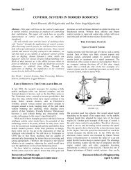
The following steps are <strong>use</strong>d in order to per<strong>for</strong>m thefixture technique: Generate <strong>digital</strong> X,Y <strong>and</strong> Z sections <strong>of</strong> the object Locate critical datum features Generate parametric primary datum Generate parametric secondary datum Place datums in CAD assembly Overlay <strong>digital</strong> sections on assembly Place part to be de<strong>for</strong>med in fixture De<strong>for</strong>m component to match datums Verify final product <strong>for</strong> accuracy using scan dataSession 3Bincomplete or obstructed from the scanners view bysurrounding components <strong>of</strong> the truck. The lack <strong>of</strong>in<strong>for</strong>mation made direct duplication <strong>of</strong> the deflected springsdirectly from the scan data impossible. There was no longeraccess to the truck itself to allow <strong>for</strong> re<strong>scanning</strong> <strong>of</strong> thedesired geometry. There<strong>for</strong>e, a method was developed toreproduce the deflected spring using its basic geometry <strong>and</strong>then modified to meet known dimensions <strong>of</strong> its deflectedcounter parts. A <strong>digital</strong> picture taken <strong>of</strong> the non deflectedspring can be seen below in Figure 1 along with its <strong>reverse</strong>engineered CAD model.CASE STUDYIn this case study the overall project involved the <strong>reverse</strong>engineering <strong>of</strong> a production model Peterbuilt truck. Thetruck’s geometry was captured using <strong>digital</strong> white light<strong>scanning</strong> technology <strong>and</strong> then reproduced into a CADmodel. The model would then be <strong>use</strong>d in a dynamicsimulation program called ADAMS-car. Once in ADAMS-Car roll over analysis <strong>of</strong> the truck could be conducted <strong>and</strong>then analyzed. The resulting data would then be <strong>use</strong> by thePeterbuilt Company, which produces the truck.The research was conducted at Western MichiganUniversities Center <strong>for</strong> Advanced Vehicle Design <strong>and</strong>Simulation (CAViDS) laboratory. The project was tasked to<strong>reverse</strong> engineer components, verses simply retrieving priorCAD files from the company, in order to factor inmanufacturing differences <strong>and</strong> variances which the idealCAD files neglect or cannot account <strong>for</strong>. Those variancesmade our simulations as accurate as possible to the realmanufactured trucks. [2]Towards the end <strong>of</strong> the project, several componentsneeded to be clarified or re-created prior to simulation. One<strong>of</strong> the components which needed to be worked on was thetruck’s leaf spring assembly. Three scans <strong>of</strong> the springassembly were taken <strong>for</strong> the project. From these scans threemodels would be generated. One model was <strong>of</strong> the overallspring assembly in a non-deflected state, resting on theground, while fully assembled. The second model was <strong>of</strong> thespring assembly in place on the truck. This second assemblywould be deflected but only under assembly conditions. Thetruck was lifted into the air so that no other weight wasplaced onto the spring. The third <strong>and</strong> final model would be<strong>of</strong> the spring in its deflected resting state, with the truck onthe ground <strong>and</strong> the weight <strong>of</strong> an unloaded truck bearingdown upon it. The three models would be <strong>use</strong>d to helpcalculate <strong>and</strong> verify the computer generated spring’s motion<strong>and</strong> deflection as well as to create the initial spring CADmodel.The challenge <strong>of</strong> creating the computer models wouldbe in the lack <strong>of</strong> provided in<strong>for</strong>mation. Scans <strong>of</strong> the leafspring assembly were conducted months prior to its CADduplication <strong>and</strong> be<strong>for</strong>e the need <strong>for</strong> multiple models wouldbe required or even requested. Complete scans <strong>of</strong> the leafspring assembly, in its not deflected state, were conducted.However scans <strong>of</strong> the mounted spring were eitherFigure 1Non Deflected Spring (top) RE CAD Model (bottom)Though the scans did not allow <strong>for</strong> direct duplication,they did however capture key areas where the spring was tobe mounted relative to other components in its deflectedstate. Also some geometry <strong>of</strong> the spring was captured thatallowed <strong>for</strong> referencing based upon mounting points. Inother words the scanner revealed datum points <strong>and</strong> key crosssections <strong>of</strong> the spring. Enough key points existed that amodel <strong>of</strong> the non deflected spring could be modified <strong>and</strong>aligned with these points to reproduce its deflectedcounterpart.To modify the non deflected model, a <strong>for</strong>m <strong>of</strong> <strong>digital</strong><strong>checking</strong> fixture was created using the datum pointscaptured in the scan. Like a real life measuring fixture, thedatum points would hold the work piece in place while themain cross sections <strong>of</strong> the spring were bent <strong>and</strong> manipulatedto match the known cross-sections which were captured inthe partial scan. The non de<strong>for</strong>med spring would bemanipulated till it would align with the known sections <strong>of</strong>the de<strong>for</strong>med spring. Once finalized the de<strong>for</strong>med springwas then re-inserted into the known scanned geometry to beverified <strong>and</strong> to calculate percentage error. This techniqueallows <strong>for</strong> accurate reproduction beca<strong>use</strong> the s<strong>of</strong>twarechanges the model according to how the metal wouldde<strong>for</strong>m under loading conditions.Pittsburgh, PA March 26 - 27, 2010ASEE North Central Sectional Conference3B-2
Technique StepsFor this project an ATOS II white light scanner was <strong>use</strong>d toscan part geometry. [3] Once scanned, the surface geometry<strong>of</strong> a part is stored inside the attached s<strong>of</strong>tware. The ATOSs<strong>of</strong>tware allows a <strong>use</strong>r to divide up the scanned surface intosections. Too accurately model components in this way,sections along the X, Y <strong>and</strong> Z axis were made at fivemillimeter increments. An example <strong>of</strong> the spring sectionsalong the X-axis can be seen in Figure 2. In this figure thesections are overlaid on the part. When these sections areoverlaid on top <strong>of</strong> one another the entire part can be seen inthree dimensions. This is the starting point to this <strong>reverse</strong>technique.Figure 2Scan Sections Overlaid on ModelThe second step in creating the <strong>digital</strong> fixture was tolocate <strong>and</strong> identify the main datum reference points, then tocreate a three dimensional solid primitive to act in its place.In the case <strong>of</strong> the leaf spring, these points were the two ends<strong>of</strong> the spring <strong>and</strong> the top assembly mounts. All three <strong>of</strong>these primary points are bolt locations <strong>and</strong> regardless <strong>of</strong> theamount <strong>of</strong> deflection, these points will always be bolted inthese locations. An example <strong>of</strong> the described location canbe seen highlighted in Figure 3.Session 3Bboth a known size <strong>and</strong> had their geometry captured in allthree scans. An example <strong>of</strong> the finished first step can beseen in Figure4.Figure 4Primitive Cylinders with Spring <strong>for</strong> ReverenceThe third step in creating the fixture was to locate <strong>and</strong>represent secondary datums. In the springs case thesecondary datum would be where surfaces <strong>of</strong> the springwould come in contact with known surfaces <strong>of</strong> the truck.For example the leaf spring included a mounting platewhich not only rein<strong>for</strong>ced the bolt <strong>for</strong> the center axle mountbut also came in full contact with the axle itself. Also, twomounting plates, which are perpendicular to their mountingbolts at either end <strong>of</strong> the spring, were located. These arepoints which, like the bolts from the first step, will neverchange being in contact. However they are not as critical asthe bolt locations beca<strong>use</strong> there have larger variances. Thesesurfaces can shift <strong>and</strong> slide depending on the amount <strong>of</strong>deflection <strong>and</strong> how they were assembled. For example theends <strong>of</strong> the spring will bolt to the frame <strong>of</strong> the vehicle <strong>and</strong>prevent the spring from translation along the X, Y, <strong>and</strong> Zaxis. The surface <strong>of</strong> the vehicle frame, that the spring isbrought up against, prevents translation in only the Z axis<strong>and</strong> prevents rotation. Beca<strong>use</strong> the surface allows <strong>for</strong> alarger degree <strong>of</strong> translational movement <strong>and</strong> is not as criticalto the overall design intent, as the bolts, the surfaces are asecondary reference. After locating these points, they wererepresented in the CAD model by solid surfaces which thespring primitive would be joined against using matecomm<strong>and</strong>s. An example <strong>of</strong> the third step can be seen belowin Figure 5.Figure 3Primary Datum LocationsThese points represented the primary datum points. Theprimitives where made as cylinders, which represented thebolts that affix the spring in reality. All three <strong>of</strong> the bolts areFigure 5Primary <strong>and</strong> Secondary Datums with Spring <strong>for</strong> ReferenceThe final step in creating the fixture was to import thescanned sections <strong>of</strong> the deflected leaf spring into the fixturemodel. The imported sections were transferred into themodel as an IGES <strong>for</strong>mat. The points were then overlaidPittsburgh, PA March 26 - 27, 2010ASEE North Central Sectional Conference3B-3
onto the already created solid primitives from the previoussteps. This newly imported data would serve to act as aguide when trans<strong>for</strong>ming the model <strong>and</strong> to verify thelocations found in the previous steps. These cross sectionsalso would act as a tertiary datum point.Once the fixture was complete <strong>and</strong> verified using theIGES file, by overlay, the completed assembly <strong>of</strong> the nondeflectedleaf spring was then added to the fixture assembly.Once oriented, one <strong>of</strong> the main datum points were aligned<strong>and</strong> affixed to the fixture model as described in Figure 6.From this point the next set <strong>of</strong> bolt locations were placed.Using several computerized comm<strong>and</strong>s, which allowthe model to be de<strong>for</strong>med without changing its overalldimensions, the other main datums were then aligned <strong>and</strong>checked <strong>for</strong> interference. Below in Figure 8 shows thespring after it has been <strong>for</strong>med to meet the primary <strong>and</strong>secondary datum points. Once interferences were eliminated<strong>for</strong> the main datum points, the de<strong>for</strong>ming process wasrepeated matching the cross section <strong>of</strong> the spring to thefixture. The cross section allows <strong>for</strong> very fine geometricdeflections to be captured.Figure 6Spring Be<strong>for</strong>e De<strong>for</strong>mationSession 3BAfter the desired component is created <strong>and</strong> verified itcan be compared against its counterpart in a Finite ElementAnalysis (FEA) program in order to determine stress <strong>and</strong>strain characteristics. In the case <strong>of</strong> the leaf spring both thenon-deflected <strong>and</strong> deflected models were overlapped in FEA<strong>and</strong> combined with the known loading <strong>of</strong> the truck. Fromthis in<strong>for</strong>mation a stress strain curve was generated <strong>and</strong>mapped along with a stress distribution along the geometry.Once the stresses <strong>and</strong> strains are known they can be <strong>use</strong>d toin an extremely accurate representation <strong>of</strong> how the springwill behave can be made in the dynamic simulation.CONCLUSIONIn the case <strong>of</strong> the spring the overall process <strong>of</strong> taking theCAD model <strong>and</strong> creating the fixture took approximately onehour. An additional hour was needed to both modify thescan sections so that they could be overlaid <strong>and</strong> tomodifying the part <strong>for</strong> deflection. From start to finish thisre-engineering technique took about two hours time makingthis technique much faster than making doing it manually.Above all this technique allowed the project to be completedwithout the actual spring present <strong>and</strong> was far more accuratein its results then manually <strong>checking</strong>.This method can be <strong>use</strong>d <strong>for</strong> any component which hasto be de<strong>for</strong>med <strong>for</strong> analysis as long as there is a preexistingCAD file along with deflected scan data. Using thistechnique parts such as beams, springs, cantilevers orirregular geometry solids can be <strong>reverse</strong> engineered usingminimal data.Figure 6Spring After De<strong>for</strong>mation (Primary <strong>and</strong> Secondary Datums)After this process had been concluded a secondinterference check was run to see if the spring model cameinto contact with the imported IGES file. Following a series<strong>of</strong> minor adjustments, the newly de<strong>for</strong>med model <strong>of</strong> the leafspring now lined up with the reference geometry. The finalinterference check, with the sections, found that the springwas within less than one thous<strong>and</strong> <strong>of</strong> an inch <strong>of</strong> deviationfrom the IGES overlay. Given that the scanner being <strong>use</strong>dallowed <strong>for</strong> greater inaccuracy than the deviation foundbetween the scan data, the model was deemed an acceptablereproduction. This process was repeated to successfullygenerate the second partially deflected spring.With the deflected spring complete the CAD model wasbrought into the ATOS s<strong>of</strong>tware <strong>for</strong> a final verification. Theraw scan data holds many more data points <strong>for</strong> comparisonthan the sections making the verification in ATOS evenmore reliable than relying on the sections alone. Thesections were <strong>use</strong>d due to data transfer <strong>and</strong> ease <strong>of</strong>preliminary <strong>use</strong> however a lot <strong>of</strong> data is lost in thesectioning process. There<strong>for</strong>e it is highly recommended thatthe actual scanned surfaces be <strong>use</strong>d <strong>for</strong> final modelverification. If an extreme degree <strong>of</strong> accuracy is not needed<strong>for</strong> the component then this step can be neglected.REFERENCES[1] Lombard, M, SolidWorks Surfacing <strong>and</strong> Complex Shape ModelingBible, Indianapolis, Indiana, Wiely Publishing Inc, 2008.[2] Ingle, K, Reverse Engineering, Washington, DC, McGraw Hill, inc.1994.[3] Optical Measuring Techniques. 2006. ATOS User Manua v6. OrderNumber: D-38106 Braunschweig, Germany.AUTHOR INFORMATIONSean Derrick Masters Student, Western MichiganUniversity, College <strong>of</strong> Engineering <strong>and</strong> Applied Science,Kalamazoo, MI, 49007, s4derric@wmich.eduSean studied engineering design <strong>and</strong> graduated fromWestern Michigan University in Spring 2009. He iscurrently a graduate student studying manufacturingengineering at Western Michigan University specializing in<strong>reverse</strong> engineering, design <strong>for</strong> manufacturability <strong>and</strong>conceptual machine design. After his masters degree, heplans to begin a career in military research <strong>and</strong>development.Pittsburgh, PA March 26 - 27, 2010ASEE North Central Sectional Conference3B-4