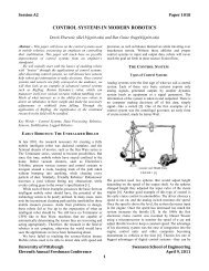
design and construction of mobile surveillance robot
design and construction of mobile surveillance robot
design and construction of mobile surveillance robot

Create successful ePaper yourself
Turn your PDF publications into a flip-book with our unique Google optimized e-Paper software.
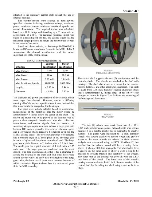
attached to the stationary central shaft through the use <strong>of</strong>internal bearings.The electric motors were selected to meet severalspecified criterion including maximum voltage, maximumpower, minimum torque, minimum rotational speeds, <strong>and</strong>overall dimensions. The required torque was calculatedbased on a 10 lb <strong>design</strong> with traveling up a 5˚ ramp with anacceleration <strong>of</strong> 2 ft/s 2 . The required rotational speed wasbased on a desired speed <strong>of</strong> 5 ft/s. The desired length was themaximum length possible to mount the motors back to backin the center <strong>of</strong> the <strong>robot</strong>.Based on these criteria, a Portescap B-230013-12Abrushless DC motor was chosen for use in the MSR. Table 2summarizes the desired specifications <strong>and</strong> the actualspecifications <strong>of</strong> the motor chosen.CriterionTable 2: Motor Specifications [4]Desired MotorSpecification SpecificationMax. Voltage 12 V 12 VMax. Power 20 W 28.8 WMin. Torque 0.75 in-lb 1.0 in-lbMin. Rotational Speeds 480 RPM 2650 RPMLength < 1.75 in 1.44 inDiameter < 1.5 in 2.22 inThe diameter <strong>and</strong> power consumption <strong>of</strong> the selected motorwere larger than desired. However, due to a difficultymeeting all <strong>of</strong> the desired specifications, it was decided thatthis motor would be acceptable for the <strong>design</strong>.The gears were initially selected based on dimensionalrequirements <strong>of</strong> the motor so that the motor would beapproximately 3 inches below the center <strong>of</strong> the shaft. Thereason the motor was to be placed at this location was toprevent electromagnetic interference with data collection,transmission, <strong>and</strong> control signals from the motors. Asecondary <strong>design</strong> requirement was to have a large gear ratiobecause DC motors generally have a high rotational speed<strong>and</strong> a low torque which needed to be stepped down for theMSR’s desired speed. The two spur gears that were selectedhad a pressure angle <strong>of</strong> 20˚<strong>and</strong> a pitch <strong>of</strong> 16. The large gearis made <strong>of</strong> nylon <strong>and</strong> the pinion in made <strong>of</strong> steel. The largegear has a pitch diameter <strong>of</strong> 5 inches with a 0.5 inch bore.The small gear has a pitch diameter <strong>of</strong> 1 inch with a 0.25inch bore. The large gear was modified from the stock<strong>design</strong>. The bore was increased so that it has a clearance fitaround the bearing on the shaft, <strong>and</strong> four small holes weredrilled into the wheel to allow it to be attached to the largegear. Also, the hubs on all gears were removed because <strong>of</strong>width constraints. Figure 6 shows how the motors <strong>and</strong> gearsfit in the MSR assembly.FIGURE 6MECHANICAL DRIVE SYSTEMSession 4CThe central shaft supports the two (2) hemispheres <strong>and</strong> thecentral cylinder. The wheels are attached to the shaft withbearings. The shaft also serves as a mount for the camera,motors, batteries, <strong>and</strong> other electronic equipment. The shaftis made from 0.75 inch diameter circular aluminum stockthat is approximately 12 inches long. It has six (6) stepchanges as shown in Figure 7 to facilitate the mounting <strong>of</strong>the bearings <strong>and</strong> the camera:FIGURE 7SHAFT DESIGNThe two (2) wheels were made from two 12 x 12 x0.375 inch polycarbonate plates. Polycarbonate was chosenbecause it is a durable plastic that is permeable to electricsignals. The plates were machined to 12 inch diameterwheels with cutouts (spokes) to reduce weight <strong>and</strong> provideaccess to the space outside the wheels. A finite elementanalysis was conducted using ANSYS Workbench ® thatverified that the wheels would still have a safety factorabove 10 when a 10 lb load was apply. The wheels also havea groove on the outer edge to allow a wide o-ring to beattached to provide traction <strong>and</strong> durability to the wheels.The outer race <strong>of</strong> the bearing was press-fit onto the 1.375inch bore <strong>of</strong> the wheel. The inner race <strong>of</strong> the wheel’sbearing was secured onto the 0.5 inch diameter section <strong>of</strong> thecentral shaft by threading the shaft using a nut to fix it inplace.Pittsburgh, PA March 26 - 27, 2010ASEE North Central Sectional Conference4C-4