Xilinx - Design Reuse Methodology for ASIC and FPGA Designers.pdf
Xilinx - Design Reuse Methodology for ASIC and FPGA Designers.pdf
Xilinx - Design Reuse Methodology for ASIC and FPGA Designers.pdf

You also want an ePaper? Increase the reach of your titles
YUMPU automatically turns print PDFs into web optimized ePapers that Google loves.
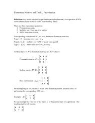
24module critical_good (in0, in1, in2, in3, critical, out);input in0, in1, in2, in3, critical;output out;assign out = ((in0&in1) | ~in2) & ~in3 & ~critical;endmodulein0in1in2in3criticalout3.4 Tristate vs. Mux BusesFigure 15 - Critical Path after RecodingThe first consideration in designing any on-chip bus is whether to use a tristate bus or amultiplexer-based bus. Tristate buses are popular <strong>for</strong> board-level designs <strong>and</strong> are also commonlyfound in <strong>FPGA</strong>-based designs, because they reduce the number of wires <strong>and</strong> are readily availableon many <strong>FPGA</strong> devices. Tristate buses are problematic <strong>for</strong> on-chip interconnection since it isessential that only one driver is active on the bus at any one-time; any bus contention, withmultiple drivers active at the same time, can increase power consumption <strong>and</strong> reduce thereliability of the chip. There are additional problems in <strong>ASIC</strong>s that do not exist <strong>for</strong> <strong>FPGA</strong>s. Forexample, <strong>ASIC</strong> designers must make sure that tristate buses are never allowed to float. <strong>FPGA</strong>technologies provide weak keeper circuits that pull-up the floating bus to a known value.Tristate buses are especially problematic <strong>for</strong> modules designed <strong>for</strong> reuse. There are a limitednumber of tristate resources (i.e., tristate buffers connected to interconnect) in each device family<strong>and</strong> device size within a family. The next designer may not have enough resources available,<strong>for</strong>cing a significant redesign.Guidelines – We recommend using multiplexer-based buses when designing <strong>for</strong> reuse since theyare technology-independent <strong>and</strong> more portable.3.5 Arithmetic Functions<strong>FPGA</strong> architectures designed <strong>for</strong> system level integration contains dedicated carry logic circuitrythat provides fast arithmetic carry capabilities <strong>for</strong> high-speed arithmetic functions. The dedicatedcarry logic is generally inferred by the synthesis tools from an arithmetic operator (i.e., +, -, /). Inthe <strong>Xilinx</strong> Virtex architecture a 16x16 multiplier can effectively use the carry logic from themultiplier oper<strong>and</strong> “*” <strong>and</strong> operate at 60MHz non-pipelined <strong>and</strong> 160MHz with pipeline stages.Many synthesis tools have libraries of pre-optimized functions, such as Synopsys <strong>Design</strong>Warelibraries, which can be inferred from RTL code as shown in the example following.sum = a_in * b_in.