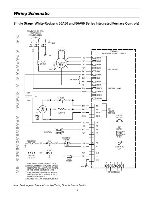
Wiring SchematicSingle Stage (White-Rodger’s 50A50 and 50A55 Series Integrated <strong>Furnace</strong> Controls)12120 VOLT, 60 HZ., 1 PH.POWER SUPPLYPER LOCAL CODESNHGNDCF3456789WH/1BKGRDOORSWITCHGNDGNDGRBRBRI.D.BLOWERMTR.BK“A”“B”“C”BK/1BK/4COOLHEATPARKPARKLINEXFMR50A50-ALLINTEGRATED FURNACE CONTROLHOT 120VAC0OPTIONALBK/3BK/2EACHUMqWHWH/1CIR NLINE NNEUTRAL 120VACwertyuiopasdfghjkl;zYL/4120V24VTNSFUSE LINK4FUSE LINK2 3 4GRGNDIND.MTR.YL/2YL/3BKWHGAS VALVETCOTCO-B321, 3YL/11 USED ON 90% FURNACE MODELS ONLY.2 DIRECT VENT MODELS HAVE ONE MANUALRESET FLAME ROLL OUT SWITCH INSTEADOF TWO, SINGLE-USE FUSIBLE LINKS.3 USED ON DOWNFLOW/HORIZONTAL ANDUPFLOW/HORIZONTAL MODELS. TCO-B ISREVERSE FLOW SWITCH.4 MAY BE A FUSE LINK OR BIMETAL SWITCH.BKWH1 TCO-BIGNITORCMBKWHPRESSURESWITCHFLAMESENSORWH/4BK/6BK/5WH/6WH/5BLRDBL/1RD/1ORYLYL/5WHGNDGR1234639124510711128XFMR NEAC NHUM NINDIGNIND NIGN NTRTHMVMVPSHLIHLOFPGNDHOT120VACNEUTRALJUMPER50A50-571DIPSWITCHONOFF123DIAGNOSTICLEDY W G R CTO THERMOSTATNote: See Integrated <strong>Furnace</strong> Control on Timing Chart for Control Details.15
Two Stage 50A51 Sequence of <strong>Operation</strong>White-Rodgers Integrated <strong>Furnace</strong>Control 50A51-405/-495 ModelsWhen the service disconnect 1 is in the “ON” position,power is applied through the blower door interlockswitch 6 to the controls line voltage input terminals 8and out of the control to the primary side of thecontrol transformer “XFMR” u. The secondary sideof the control transformer supplies 24 volts to thecontrol through terminal “TH” and “TR” po. Controlterminal “R” ; supplies 24 volts to the “R” terminalof the room thermostat.Once power is applied, the control flashes the LEDlight “ON” for one second and performs a self checkroutine. Following the normal system check, thecontrol flashes the LED one time per second (slow flash)continuously while in stand-by.On a call for heat, 24 volts is applied from the roomthermostats “W1” terminal to the “W1” terminal zon the control. The control checks and confirmsnormally closed contacts at the temperature cut out“TCO” j, auxillary limit (downflow and someupflow/horizontal models), the flame roll-out fuse link(two fuse links are used on downflow and upflow/horizontal models) l and normally open contacts atthe safety pressure switch #1 j. With all safety andcontrol switches in their proper position, the controlwill energize the induced draft motor on high speed wand flashes the LED two times per second continuously(fast flash) during a call for heat.When safety pressure switch “#1” j closes, thecontrol switches the induced draft motor to low speed wand begins the ignition sequence. The hot surface|ignitor w is energized for several seconds (see note)allowing the thermal element to heat up. The controlthen switches 24 volts to its “MVL” and “MV COM” gterminals to terminals #1 g and #2 f on the gasvalve. The redundant and main solenoids are energizedallowing gas flow and main burner ignition. Whenflame current is sensed by the control through its“FP” ; terminal, the 45 second indoor blower motortime delay “ON” begins. Flame failure response timeis set for 2 seconds. After flame has been establishedfor 10 seconds, the flame failure response time isreset for 0.7 seconds. If flamed current is not sensed bythe control within the trial for ignition period (see note),the main valve low and redundant gas valvesolenoids g, a are de-energized. The control willbegin a interpurge cycle and adds additional secondsto the hot surface ignitor warm-up timing (see note).The control energizes the gas valve for the secondattempt to establish main burner ignition. If againflame current is not sensed by the control within thetrial for ignition period (see note), the control will repeatthe previous cycle before locking out. At the end ofthe indoor blower motor delay “ON” timing, linevoltage is applied at control terminal “HEAT LO” 6energizing the indoor blower motor at low heat fanspeed, supplying warm air to the space.If the temperature in the space continues to fall, thethermostat second stage contacts “W2” close.24 volts is switched from thermostat terminal “W2” tothe “W2” terminal z on the control. A 30 second,2nd stage recognition time delay begins. At the end ofthe 30 second delay, the induced draft motor isswitched to high speed w causing pressure switch #2 dto close. When pressure switch #2 closes, 24 volts isswitched from control terminal “MVH” d to the gasvalve terminal #3 d energizing the second stagesolenoid allowing increased gas flow to the burners.At the same time, the indoor blower motor isswitched to high heat fan speed 7.When second stage thermostat contacts “W2” satisfy,the induced draft motor is switched back to low speed wcausing pressure switch #2 d to open breaking thecircuit to the second stage gas valve solenoid d. <strong>Gas</strong>flow is reduced to the burners. The indoor blowermotor will switch back to low heat fan speed after a30 second delay 6.When first stage thermostat contacts “W1” satisfy,the main valve low and the redundant gas valvesolenoids g are de-energized extinguishing mainburner flame. Once the control senses the loss offlame current (0.7 sec.) ;, the induced draft motor wis de-energized after a five second post-purge cycle.The indoor blower motor “OFF” timing begins. At theend of the indoor blower motor “OFF” timing, theindoor blower motor is de-energized and the cycleis complete.Note: See Timing Chart for details or Integrated <strong>Furnace</strong>Control Label.16