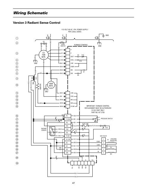
Wiring SchematicVersion 3 Radiant Sense Control1234567890qwertyuiopasdfghjklRD/4BL/4GRGNDBK/4120V.TNS24V.WH/4IGNITORBRWHWHCFI.D.FANMTR.**WHBRGRNGNDRADIANTSENSORHOTWH/1VENTMTR.**COMNONCK7“C”“B”“A”BKBK/1BK/4BK/6BK/5WH/1WHWH/6WH/5WH/4WH/2COLDWH/3K1BK/1WH/7115 VOLT 60 HZ. 1PH. POWER SUPPLYPER LOCAL CODESHDOORSWITCHK2K4BK2ABKPCP COMPOROIFSOFSIFS MVHI LIMGEGCGRGMPPHEATCOOLLINEXFMRINDIGNLINECIRCINDIGNXF MRFURNACE CONTROLOR/1BRORYL/3K4YL/1BR/2BL/1OR/2RD/1K3K6K1BK1AK7FUSE LINKK6K3C G W R TR THYL/2GRGNDEQSOCOMRMNCPRESSURE SWITCHNOTCOGAS VALVE12345GNDIMPORTANT: FURNACE CONTROLREPLACEMENT MUST BE AUTHORIZEDO.E.M. PART ONLYPART NO. KIT 3793R1(HOLDINGRESISTOR)RVMVBLGRWHRDBL/4RD/447
White-Rodgers 50A52-100/101/102 Sequence of <strong>Operation</strong>Version 4 (E93, E1, E2, E3) 5 Relays,3 Wire Flame Switch Radiant SensorThis control contains a micro-processor allowing asingle re-try upon ignition failure or loss of flame. It is a“two try” board. It also provides an automatic resetafter three hours following a system lock-out condition.When the disconnect is in the “ON” position 1, poweris applied through the blower door interlock switch 2to the control line voltage input terminal 5 and out ofthe control to the primary side of the control transformer“XFMR.”6 The low voltage side of the transformer 9supplies 24 volts to the control through terminals “TH”and “TR.”l Control terminal “R” l supplies 24 voltsto the “R” terminal on the room thermostat.24 Volt Power OnWhen 24 volt power is present at terminals TH andTR l on the furnace control, no relays are activated. Inthis model, the K1 indoor fan cooling relay will only beenergized when power is applied to the “G” terminal lon the furnace control. In the event of a limit trip o, theindoor fan motor 3 will run at the chosen heating speed.Typical Start UpOn a call for heat, the indoor thermostat completesthe circuit from the “R” terminal to “W” to the commoncontact of the combustion air pressure switch u throughthe limit switch and roll-out fuse link o. (On downflowand horizontal models, an additional limit switch andfuse link may be used.) It also starts the micro-processor.As the control micro-processor is energized, the K 3normally open relay contacts closes 7, and starts theInduced Draft Motor 0. When the Induced Draft Motorcomes up to speed, the combustion air pressure switchu trips supplying power through the normally closed(cold) radiant sensor contacts a to the redundant hand EQSO gas valve terminals f. The hot surfaceignitor 0 is also energized when the K 4 relay contacts8 close. The flame switch radiant sensor normally closed(cold) contacts a will transfer to the hot position whensufficient radiant energy is sensed.The microprocessor k initiates a timing cycle forignition. After 17 seconds (see note), the normally openK 5 contacts j (main gas valve) will close. The controlwill allow the ignitor to remain on until a total of 90seconds (see note) have passed. If at the end of 90seconds (see note), the control has not sensed theflame switch radiant sensor bi-metal trip, it will lockout.If the flame switch radiant sensor bi-metal has trippednormally within time allowed, the gas valve will beenergized through K 5 j. Two things then happen, the45 second indoor fan heat-on time delay will start and a90 second flame proving cycle will be started.After the gas valve has been energized for one second,the ignitor is de-energized.Providing the furnace fires normally, the cycle willcontinue until a normal shut-down.If the flame switch radiant sensor bi-metal resets tothe normally closed (cold) position a, indicating no flame48is present, within the 90 second flame proving time, onere-try will be initiated after a 60 second purge by the combustionblower. If this re-try fails, the control will lock out.After the furnace is in normal operation for more than90 seconds, any fault causing a burner shut-down willbe followed by two tries for re-ignition. This is calleda recycle.Typical Shut DownWhen the thermostat is satisfied and power isremoved from the “W” terminal l, the gas valve isde-energized. The indoor fan time delay circuitkeeps contacts K 2 3 closed for approximately 90seconds to allow all of the heat to be extracted fromthe furnace. When the contacts open, the indoorblower stops, unless constant fan was selected.Circuit Safety FeaturesThe circuit is arranged to prove that the combustionblower 0 is operating. The pressure switch normallyopen contacts u must always start in the normally openposition and trip to a closed position, proving that theswitch is functioning. This also proves that the InducedDraft Motor is circulating air through the furnace.The flame switch radiant sensor bi-metal signals itstripped or “hot” position a to the micro-processor s.This circuit maintains safe operation of the gas valve.If the flame switch radiant sensor bi-metal is “hot” atthe start of a cycle, the redundant valve h cannot bepowered since the normally closed contacts would beopen. Resistor EQSO (Electrical Quick Shut Off) providescurrent flow enough to hold the redundant valve open,but will not allow it to open from a closed position f.If either limit device opens o, (due to high heatexchanger temperature or roll-out), relay K 2 3 willpower the indoor blower on the selected heating speedand relay K 3 7 will power the combustion blower.In both of these cases, the indoor blower and thecombustion blower will be powered until the limitre-sets. The combustion blower will then stop immediatelybut the indoor blower will continue with the normalblower shut-down sequence. E93 and E1 controls willthen energize the ignitor and begin another ignitionsequence. E2 controls will not energize the ignitor untilthe radiant sensor trips to the cold position.A momentary power interruption will cause the microprocessork to de-energize and break the holdingcircuit. This will cause the system to enable a re-start onlyafter the pressure switch opens and then closes again,proving its operation i.A momentary gas interruption will cause the flameswitch radiant sensor to start cooling. In about 30seconds, the switch will transfer to the cold position a,closing the main valve j and stopping gas flow. Thenormal ignition start-up cycle will begin if the thermostatis calling for heat.Note: 50A52-101 (E93, E3) and 50A52-102 (E90, E4) have amimimum warm up time of 12 seconds and a maximumtime of 30 seconds