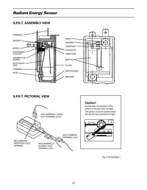
Radiant Energy SensorS.P.D.T. ASSEMBLY VIEWTERMINALMAGNETEPOXYSTATIONARYCONTACTCALIBRATIONSCREWSTATIONARYARMTERMINALRIVETRIVETWASHERTERMINALCONTACTSARMATUREBIMETALGLASSSWITCHCASEBRACKETS.P.D.T. PICTORIAL VIEWWH/7 NORMALLY OPENHOT TERMINAL (3/16")Caution!Do Not alter the position of theignitor or the gas may not light.The ignitor must be located withinthe burner face as shown at right.WH/2 COMMONTERMINAL (1/4")RED MARKINGIDENTIFIES COLDTERMINALWH/3 NORMALLYCLOSED COLDTERMINAL (1/4")Fig. 2 18-CN12P23-141
White-Rodgers 50A52-100 Sequence of <strong>Operation</strong>Version 1 (E90) 7 Relays, 2 Wire FlameSwitch Radiant SensorThis control allows a constant re-try for ignition aftera flame failure.When the disconnect is in the “ON” position, 1 poweris applied through the blower door interlock switch 2 tothe control line voltage input terminal 6 and out of thecontrol to the primary side of the control transformer“XFMR” 7. The low voltage side of the transformer 0supplies 24 Volts to the control through terminals “TH”and “TR” ;. Control terminal “R” ; supplies 24 voltsto the “R” terminal on the room thermostat.24 Volt Power OnWhen 24 volt power is present at terminals TH and TRon the furnace control, relay K 5 k will be energizedthrough the flame roll-out fuse link and limitswitch p. (On horizontal and downflow models, anadditional limit switch and fuse link may be used.)The normally closed K 5A contacts open ; and thenormally open K 5B contacts close z. This prevents theK 1 cooling relay z from being energized until poweris applied to the “G” terminal ; on the furnace control.Note: If the limit switch or the flame roll-out fuselink opens, relay K 5 k will be de-energized and thenormally closed K 5A contacts ; will complete acircuit to the K 1 cooling relay z. The indoor blowermotor will run on the cooling speed selected.Typical Start UpOn a call for heat, the indoor thermostat completesthe circuit from the R terminal to W then through thelimit switch and roll-out fuse link to the commoncontact of the combustion air pressure switch i andthus to relays K 2 and K 7 i.When relay K 2 i is energized, its K 2A contactsclose u, providing a holding circuit for itself. ContactsK 7 i also close, and start the Induced Draft Motor q.When the Induced Draft Blower comes up to speed, thecombustion pressure switch trips, connecting power(through the flame switch NC radiant sensor bi-metal) a,to relays K 4 and K 6 d.When relay K 6 d is energized, its contacts 9 connectline power to the ignitor q. Also, normally open contactsK 4B h close, bypassing the EQSO (Electrical QuickShut Off) resistor f and allowing the redundant gasvalve h to pull in. Normally closed contacts K 4A jopen, removing power from the K 3 l fan time delaycircuit and the main gas valve. As the ignitor heats up,its’ radiant energy is sensed by the flame switch radiantsensor bi-metal which will cause the contacts to open.When the contacts open, relays K 6 and K 4 dare de-energized allowing contacts K 6 to open 9,de-energizing the ignitor. At the same time, normally42open contacts K 4B h open, but the redundant valveis held open due to the EQSO resistor in series with theRV coil. Normally closed contact K 4A j closes, allowingthe main valve to open (thus gas flows and ignitiontakes place) and the K 3 fan time delay circuit startsthe time delay to start the indoor blower 4 (normally a45 second delay), then warm air circulation begins.Typical Shut DownWhen the thermostat is satisfied and power is removedfrom the “W” terminal ;, the gas valve is de-energized.The time delay circuit keeps contacts K 3 4 closed forapproximately 90 seconds to allow all of the heat to beextracted from the furnace. When the contacts open, theindoor blower stops.Circuit Safety FeaturesThe circuit is arranged to prove that the combustionblower is operating. The pressure switch i must alwaysstart in the normally closed position and then trip to anopen position, proving that the switch is functioning. Thisalso proves that the Induced Draft Motor q is circulatingair through the furnace.The flame switch radiant sensor bi-metal a controls relayK 4. Its contacts maintain safe operation of the gas valve.If the flame switch is open at the start of a cycle, theredundant valve h cannot open due to the normallyopen contacts K 4B h. (The EQSO resistor providescurrent flow enough to hold the valve open, but willnot allow it to open from a closed position).If the limit switch opens, (due to high heat exchangertemperature), it will power the indoor blower by deenergizingrelay K 5 k, thus energizing relay K 1 z andturning on the blower on cooling speed 5.A momentary power interruption will cause relay K 2 ito de-energize and break its holding circuit u. This willcause the circuit to restart only after the pressure switchcloses again, proving its operation.A momentary gas interruption will cause the flame switchradiant sensor bimetal a to start cooling. In about 30seconds, the switch will close, energizing relay K 4, dthus opening the normally closed contact K 4A jclosing the main gas valve j and stopping gasflow. Relay K 6 and K 4 d will be energized, and anew start up cycle will begin.Note: This furnace has been certified to allow unburnedgas to flow for a stated “flame failure response time”and then be ignited without excessive flame roll-out.The roll-out fuse link will open the circuit and stop gasflow if it is overheated due to a flame roll-out. (Ondownflow and horizontal models, an additional limitswitch or fuse link may be used.) As an example, this mayoccur with a blocked flue. At this time, the indoor blowerwill be powered on the selected cooling speed.