

Residential Gas Furnace Operation - HVAC.Amickracing
Residential Gas Furnace Operation - HVAC.Amickracing
Residential Gas Furnace Operation - HVAC.Amickracing

You also want an ePaper? Increase the reach of your titles
YUMPU automatically turns print PDFs into web optimized ePapers that Google loves.
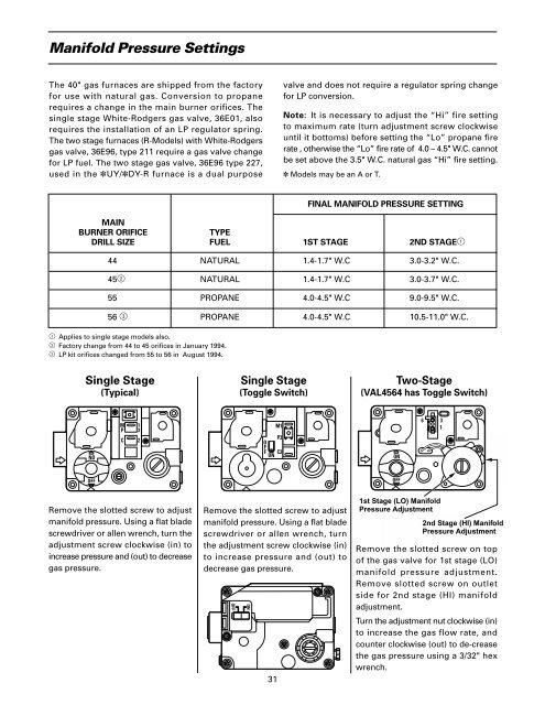
Manifold Pressure SettingsThe 40" gas furnaces are shipped from the factoryfor use with natural gas. Conversion to propanerequires a change in the main burner orifices. Thesingle stage White-Rodgers gas valve, 36E01, alsorequires the installation of an LP regulator spring.The two stage furnaces (R-Models) with White-Rodgersgas valve, 36E96, type 211 require a gas valve changefor LP fuel. The two stage gas valve, 36E96 type 227,used in the ✽UY/✽DY-R furnace is a dual purposevalve and does not require a regulator spring changefor LP conversion.Note: It is necessary to adjust the “Hi” fire settingto maximum rate (turn adjustment screw clockwiseuntil it bottoms) before setting the “Lo” propane firerate , otherwise the “Lo” fire rate of 4.0 – 4.5" W.C. cannotbe set above the 3.5" W.C. natural gas “Hi” fire setting.✽ Models may be an A or T.FINAL MANIFOLD PRESSURE SETTINGMAINBURNER ORIFICETYPEDRILL SIZE FUEL 1ST STAGE 2ND STAGE144 NATURAL 1.4-1.7" W.C 3.0-3.2" W.C.452 NATURAL 1.4-1.7" W.C 3.0-3.7" W.C.55 PROPANE 4.0-4.5" W.C 9.0-9.5" W.C.56 3 PROPANE 4.0-4.5" W.C 10.5-11.0" W.C.1 Applies to single stage models also.2 Factory change from 44 to 45 orifices in January 1994.3 LP kit orifices changed from 55 to 56 in August 1994.Single Stage(Typical)Single Stage(Toggle Switch)Two-Stage(VAL4564 has Toggle Switch)NOMPC132M1P3OFFC2 ONON6 31OFFOFFRemove the slotted screw to adjustmanifold pressure. Using a flat bladescrewdriver or allen wrench, turn theadjustment screw clockwise (in) toincrease pressure and (out) to decreasegas pressure.Remove the slotted screw to adjustmanifold pressure. Using a flat bladescrewdriver or allen wrench, turnthe adjustment screw clockwise (in)to increase pressure and (out) todecrease gas pressure.311st Stage (LO) ManifoldPressure Adjustment2nd Stage (HI) ManifoldPressure AdjustmentRemove the slotted screw on topof the gas valve for 1st stage (LO)manifold pressure adjustment.Remove slotted screw on outletside for 2nd stage (HI) manifoldadjustment.Turn the adjustment nut clockwise (in)to increase the gas flow rate, andcounter clockwise (out) to de-creasethe gas pressure using a 3/32" hexwrench.


