

Residential Gas Furnace Operation - HVAC.Amickracing
Residential Gas Furnace Operation - HVAC.Amickracing
Residential Gas Furnace Operation - HVAC.Amickracing

Create successful ePaper yourself
Turn your PDF publications into a flip-book with our unique Google optimized e-Paper software.
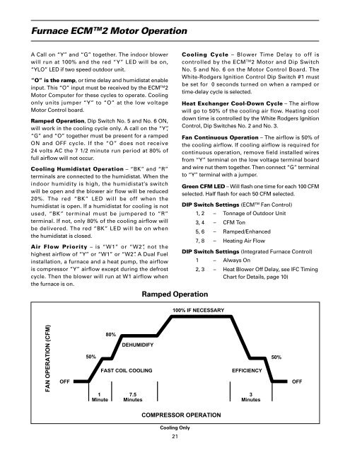
<strong>Furnace</strong> ECM TM 2 Motor <strong>Operation</strong>A Call on “Y” and “G” together. The indoor blowerwill run at 100% and the red “Y” LED will be on,“YLO” LED if two speed outdoor unit.“O” is the ramp, or time delay and humidistat enableinput. This “O” input must be received by the ECM TM 2Motor Computer for these cycles to operate. Coolingonly units jumper “Y” to “O” at the low voltageMotor Control board.Ramped <strong>Operation</strong>, Dip Switch No. 5 and No. 6 ON,will work in the cooling cycle only. A call on the “Y”,“G” and “O” together must be present for a rampedON and OFF cycle. If the “O” does not receive24 volts AC the 7 1/2 minute run period at 80% offull airflow will not occur.Cooling Humidistat <strong>Operation</strong> – “BK” and “R”terminals are connected to the humidistat. When theindoor humidity is high, the humidistat’s switchwill be open and the blower air flow will be reduced20%. The red “BK” LED will be off when thehumidistat is open. If a humidistat for cooling is notused, “BK” terminal must be jumpered to “R”terminal. If not, only 80% of the cooling airflow willbe delivered. The red “BK” LED will be on whenthe humidistat is closed.Air Flow Priority – is “W1” or “W2”, not thehighest airflow of “Y” or “W1” or “W2”. A Dual Fuelinstallation, a furnace and a heat pump, the airflowis compressor “Y” airflow except during the defrostcycle. Then the blower will run at W1 airflow whenthe furnace is on.Ramped <strong>Operation</strong>Cooling Cycle – Blower Time Delay to off iscontrolled by the ECM TM 2 Motor and Dip SwitchNo. 5 and No. 6 on the Motor Control Board. TheWhite-Rodgers Ignition Control Dip Switch #1 mustbe set for 0 seconds turned on when a ramped ortime-delay cycle is selected.Heat Exchanger Cool-Down Cycle – The airflowwill go to 50% of the cooling air flow. Heating cooldown time is controlled by the White Rodgers IgnitionControl, Dip Switches No. 2 and No. 3.Fan Continuous <strong>Operation</strong> – The airflow is 50% ofthe cooling airflow. If cooling airflow is required forcontinuous operation, remove field installed wiresfrom “Y” terminal on the low voltage terminal boardand wire nut them together. Then connect “G” terminalto “Y” terminal with a jumper.Green CFM LED – Will flash one time for each 100 CFMselected. Half flash for each 50 CFM selected.DIP Switch Settings (ECM TM Fan Control)1, 2 – Tonnage of Outdoor Unit3, 4 – CFM Ton5, 6 – Ramped/Enhanced7, 8 – Heating Air FlowDIP Switch Settings (Integrated <strong>Furnace</strong> Control)1 – Always On2, 3 – Heat Blower Off Delay, see IFC TimingChart for Details, page 10)100% IF NECESSARYFAN OPERATION (CFM)OFF50%1Minute80%DEHUMIDIFYFAST COIL COOLING7.5MinutesEFFICIENCY3Minutes50%OFFCOMPRESSOR OPERATIONCooling Only21


