

Residential Gas Furnace Operation - HVAC.Amickracing
Residential Gas Furnace Operation - HVAC.Amickracing
Residential Gas Furnace Operation - HVAC.Amickracing

Create successful ePaper yourself
Turn your PDF publications into a flip-book with our unique Google optimized e-Paper software.
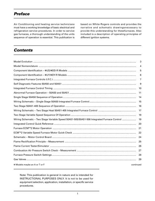
PrefaceAir Conditioning and heating service techniciansmust have a working knowledge of basic electrical andrefrigeration service procedures. In order to servicegas furnaces, a thorough understanding of the unitssequence of operation is essential. This publication isbased on White-Rogers controls and provides thenarrative and schematic drawingsnecessary toprovide this understanding for thesefurnaces. Alsoincluded is a description of operating principles ofdifferent ignition systems.ContentsModel Evolution .......................................................................................................................................................... 3Model Nomenclature .................................................................................................................................................. 4Component Identification – ✽UD/✽DD-R Models ...................................................................................................... 5Component Identification – ✽UY/✽DY-R Models ....................................................................................................... 6Integrated <strong>Furnace</strong> Controls (I.F.C.) ............................................................................................................................ 7Self Diagnostic Features 50A50 and 50A51 ............................................................................................................... 9Integrated <strong>Furnace</strong> Control Timing ............................................................................................................................ 10Abnormal <strong>Furnace</strong> <strong>Operation</strong> – 50A50 and 50A51 .................................................................................................... 11Single Stage 50A50 Sequence of <strong>Operation</strong>.............................................................................................................. 14Wiring Schematic – Single Stage 50A50 Integrated <strong>Furnace</strong> Control...................................................................... 15Two Stage 50A51-405 Sequence of <strong>Operation</strong> .......................................................................................................... 16Wiring Schematic – Two Stage Heat 50A51-405 Integrated <strong>Furnace</strong> Control ......................................................... 17Two Stage Variable Speed Sequence Of <strong>Operation</strong> .................................................................................................. 18Wiring Schematic – Two Stage Variable Speed 50A51-505/50A51-506 Integrated <strong>Furnace</strong> Control ..................... 19Integrated Control Quick Reference ........................................................................................................................... 20<strong>Furnace</strong> ECM TM 2 Motor <strong>Operation</strong> ............................................................................................................................. 21ECM TM 2 Variable Speed <strong>Furnace</strong> Motor Quick Check ............................................................................................... 22Schematic – Motor Control Board .............................................................................................................................. 24Flame Rectification Principle – Measurement ........................................................................................................... 25Flame Current Tester/Simulator ................................................................................................................................. 26Combustion Air Pressure Switch Check – Measurement ......................................................................................... 27<strong>Furnace</strong> Pressure Switch Settings .............................................................................................................................. 28<strong>Gas</strong> Valves .................................................................................................................................................................... 29✽ Models maybe an A or T or FcontinuedNote: This publication is general in nature and is intended forINSTRUCTIONAL PURPOSES ONLY. It is not to be used forequipment selection, application, installation, or specific serviceprocedures.1


