Create successful ePaper yourself
Turn your PDF publications into a flip-book with our unique Google optimized e-Paper software.
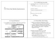
Microtime Computer Inc.3.2.3. Example_3 : InterruptScenario :This project demonstrates● How I/O pins can be configured as a trigger device for interrupt triggering.● How interrupt mechanism in uCOS-II should be organized for proper operation.When project executing, press the button in target board, KEY0, and check if LED is toggledaccordingly.Note :The control process and code explanation shown in this section is specifically used forPTK-STM32F207 and may not be applied for other platforms.Project Browsing :<strong>ePBB</strong>\Applications\Projects\PTK-STM32F207\EWARM-V6\OS_uCOS-II\base_button_irq\demo.ewwApplication groupVector tableStartup programmain() programUCOS-II boardsupport packageBSP :board device driverBSP :interrupt handling codeBSP :MCU peripheralclock control code<strong>ePBB</strong> LibrariesPTK board levelInitial programPTK LED devicedriverMCU peripheralsdriverUCOS-II :RTOS frameworkProject map fileProject image fileFigure-9. Interrupt project (OS_uCOS-II)3-15 ePPB <strong>Development</strong> <strong>Guide</strong>