Nkamouna Project Environmental & Social Assessment Executive ...
Nkamouna Project Environmental & Social Assessment Executive ...
Nkamouna Project Environmental & Social Assessment Executive ...

You also want an ePaper? Increase the reach of your titles
YUMPU automatically turns print PDFs into web optimized ePapers that Google loves.
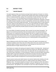
containing an underdrain system. Low perimeter berms will preclude run-on onto the Glauber Salt pad.Perimeter channels within each cell will collect precipitation and convey it to a stormwater collection pondoutside of the Glauber Salt pad.2.3.5 Tailings ManagementThe TSFs will contain the PUG and CCD tailings and associated water produced over the 24-yr mine life.The PUG TSF tailings deposition provides for deposition of the tailings from individual drop bars (openpipe discharges) strategically located around the PUG TSF perimeter. The TSF will be systematicallyfilled to form a tailings slope of approximately 0.25 percent from north to south in the facility. This willmaintain the decant pond in the southern portion of the facility. The tailings will be flocculated beforedeposition to improve sedimentation and decant development rates of the clayey tailings.The CCD TSF tailings deposition also provides for deposition from individual drop bars strategicallylocated around the CCD TSF cell perimeters. Tailings will be progressively deposited from the northernand eastern limits of the two cells to form tailings slope/beach slopes of approximately 0.5 percent to thesouthwest corners of the cells where the decant structures and underdrain collection sumps will belocated. The decant ponds in the facilities are expected to cover significant portions of each cell.The Glauber Salt will be placed into lined bulk bags at the process plant. The bags will be transported tothe GS Pad, where they will be placed, stacked, and periodically covered with plastic sheeting. It isanticipated that precipitation onto the GS Pad that contacts spilled Glauber Salt will not require watertreatment before release to the environment.2.3.6 Mineral ProcessingOre processing initially involves beneficiation, or PUG. In the PUG, ore is be crushed, scrubbed, andsized to separate the low-grade fine tailings waste from a high-grade, coarse concentrate. The coarsematerial is washed of fine particulates and dewatered before advancing to the leaching circuit. The PUGPlant has been designed to treat 8,500 tpd of ore, based on a 16-hour-per-day operating schedule.High-grade concentrate will be conveyed to the adjacent Leach Plant which will consist of a grinding mill,agitated leach tanks, thickeners, and a leach and recovery circuit. The material will go through severalstages of clarification, purification, and the CCD circuit that will dissolve specific metals into pregnant andbarren solutions. The acidic impregnated solution is separated and neutralized, causing the metals toprecipitate. The barren slurry is sent though three purification circuits to remove residual cobalt, nickel,and aluminum before the manganese carbonate precipitation circuit. Manganese carbonate will beprecipitated by the addition of soda ash.A Glauber Salt recovery circuit will be installed to treat solution from the sodium sulfate rich water pond toremove sodium sulfate as Glauber Salt (sodium sulfate decahydrate). The generated solids will bestored, bagged and transported to the Glauber Salt Pad north of the TSFs where the bags will be stackedand stored in a lined facility. GeoCam has contacted potential vendors to put in place a purchaseagreement to sell and ship off site the Glauber Salt product. The mother liquor will be used for soda ashmake-up, and excess solution will be pumped to a discharge buffer pond prior to controlled discharge tothe Edjé River.Most of the mineral process steps do not generate a waste by any definition. Instead, the processequipment is designed for a specific function in a series of physical and chemical steps to recover valuesfrom the <strong>Nkamouna</strong> ore and reject gangue minerals and other impurities at the appropriate stage in theprocess. Additionally, in the above mentioned processes and areas, scrubbers will be installed to captureemissions from vent gases in the leach and sulfide areas.Tailings management and storage was previously described in Sections 2.3.4 and 2.3.5.<strong>Executive</strong> Summary, Rev 02-5