PWR Transient Xenon Modeling and Analysis using Studsvik CMS
PWR Transient Xenon Modeling and Analysis using Studsvik CMS
PWR Transient Xenon Modeling and Analysis using Studsvik CMS
- No tags were found...

Create successful ePaper yourself
Turn your PDF publications into a flip-book with our unique Google optimized e-Paper software.
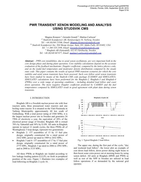
Proceedings of 2010 LWR Fuel Performance/TopFuel/WRFPMOrl<strong>and</strong>o, Florida, USA, September 26-29, 2010Paper 0116<strong>PWR</strong> TRANSIENT XENON MODELING AND ANALYSISUSING STUDSVIK <strong>CMS</strong>Magnus Kruners a , Gerardo Gr<strong>and</strong>i b , Mattias Carlsson ca) <strong>Studsvik</strong> Sc<strong>and</strong>power AB, Stenåsavägen 34, Varberg, SwedenTel: +46 (0)340 13506, Email: Magnus.Kruners@studsvik.comb) <strong>Studsvik</strong> Sc<strong>and</strong>power Inc, 504 Shoup Avenue, Suite 201, Idaho Falls, ID 83402, USATel: +1 208 528 2398, Email: Gerardo.Gr<strong>and</strong>i@studsvik.comc) Ringhals AB (Vattenfall), 432 85 Väröbacka, SwedenTel: +46 (0)340 667477, Email: mattias1.carlsson@vattenfall.comAbstract – <strong>PWR</strong> core instabilities, due to axial xenon oscillations, are very important both in thecore design phase <strong>and</strong> during plant operation. Core stability calculations depend on the accurateevaluation of the feedback mechanisms: Doppler coefficient, computed by the lattice physics code,<strong>and</strong> on the nodal fuel temperature <strong>and</strong> moderator density distributions computed by the steadystate code. This paper contains the results of typical <strong>PWR</strong> transient scenarios for which the corestability <strong>and</strong> axial xenon transients have been assessed. Such core follow axial xenon transientshave been studied by means of the <strong>Studsvik</strong> <strong>CMS</strong> code package (CASMO5 <strong>and</strong> SIMULATE5).SIMULATE5 calculations have been performed for the Ringhals-2, Ringhals-3 <strong>and</strong> Ringhals-4(<strong>PWR</strong>s) over a wide range of operating conditions – including detailed load follow <strong>and</strong> coastdown operation. The more negative Doppler coefficient predicted by CASMO5 <strong>and</strong> the fueltemperatures computed by SIMULATE5 result in good agreement with plant data during xenontransients.I. INTRODUCTIONRinghals AB is a Swedish nuclear power site with fourreactors units, three pressurized water reactors <strong>and</strong> oneboiling water reactor. It is situated on the Värö Peninsula inVarberg Municipality approximately 60 km south ofGothenburg. With a total power rating of 3560 MWe, it isthe largest nuclear power site in Sweden <strong>and</strong> generates 24TWh of electricity a year, the equivalent of 20% of theelectrical power usage of Sweden. Ringhals AB is owned70% by Vattenfall <strong>and</strong> 30% by E.ON. All units in Ringhalsoperate in typical 12 month cycles, the three <strong>PWR</strong>s all ofWestinghouse 3 loop design, represent two generations:• Ringhals 2: 157 assemblies of 15 by 15 fuel pinsdesign, originally constructed for a rated power of2432 MW T power up rated in 1989 to 2652 MW T .• Ringhals 3 <strong>and</strong> 4: 157 assemblies of 17 by 17 fuel pinsdesign, originally constructed for a rated power of2775 MW T . Ringhals 3 up rated in 2006 to 2992 MW T<strong>and</strong> in 2008 to 3135 MW T .All three <strong>PWR</strong>s at Ringhals are loaded according tolow leakage loading pattern (LLLP), no fresh in peripheralposition of the core. Figure 1 illustrates two examples ofload following on Ringhals 2 cycle 16.Fig. 1. Typical Ringhals 2 load follow.The upper one, during the first part of the cycle, “day<strong>and</strong> weekend load follow”, the lower plot an example ofcost down load follow, down power during night hours tothen boost some extra power out at morning hours by <strong>using</strong>xenon deficit. All units at Ringhals (BWR <strong>and</strong> <strong>PWR</strong>) aswell as rest of the NPP in Sweden are utilized in loadfollow operations if so dem<strong>and</strong>ed by the national gridoperator.
Proceedings of 2010 LWR Fuel Performance/TopFuel/WRFPMOrl<strong>and</strong>o, Florida, USA, September 26-29, 2010Paper 0116I.A. Sensitiveness to axial xenon oscillationsThe fuel loaded in the Ringhals <strong>PWR</strong>s has in thisstudy, an enrichment in the range of 3.40 – 3.95 wt % 235 U.About one quarter of the core is replaced per cycle (36 – 44fuel assemblies) around half of those assemblies withoutGd.The relatively low enrichment, in combination with aflat or slightly double humped axial power distribution, dooften results in cores that are highly sensitive to xenonoscillations. Fig. 2 shows the measured power <strong>and</strong> deltaflux a (DI) during a load follow close to BOC. Fig. 3 showsthe same quantities during the coast down starting at EOFP100% power (226 EFPD from BOC) <strong>and</strong> ending 44 dayslater at 69% power. Both cases show a tendency towardsaxial power shape oscillations.I.B. Operational support/guidanceTo provide support <strong>and</strong> guidance for operating coresthat are highly sensitive to xenon induced axial poweroscillations, the reactor engineer needs an accurate in-corefuel management (ICFM) system.Two ICFM systems will be considered in whatfollows, namely: ‘C4/IP3/S3’ <strong>and</strong> ‘C5/S5’. ‘C4/IP3/S3’ isshorth<strong>and</strong> for the old generation of <strong>CMS</strong> codes (CASMO-4(C4) [1], INTERPIN-3 (IP3) [2], <strong>and</strong> SIMULATE-3 (S3)[3]), while ‘C5/S5’ designates the new generation of <strong>CMS</strong>codes CASMO5 (C5) [4] <strong>and</strong> SIMULATE5 (S5) [5].Differences between these two ICFM systems,relevant for <strong>PWR</strong> transients, will be described in thispaper. CASMO5 developments, which have a significantimpact on the fuel temperature coefficient, are discussed inSection II. The SIMULATE5 fuel pin model is described inSection III. Section III includes a comparison ofSIMULATE5 predicted centerline temperatures againstHalden experimental data is included.CASMO5’s more faithful modeling of the fueltemperature coefficient, together with the SIMULATE5fuel temperature calculation, bring significantimprovements in the prediction of <strong>PWR</strong> transients.Extensive ‘C5/S5’ predictive calculations were performedfor Ringhals <strong>PWR</strong>s over a wide range of operatingconditions. A few examples of such calculations will bediscussed in Section IV.Fig. 2. Load follow <strong>and</strong> delta flux close to BOC.II. FUEL TEMPERATURE COEFFICIENTCASMO5 has many new features compared with itspredecessor CASMO-4. Among them, the replacement ofthe L-library (based primarily on ENDF/B IV data) by thelatest available nuclear data (ENDF/B VII.0) [4], <strong>and</strong> thecorrect treatment of the 238 U resonance treatment [6] have asignificant impact on the fuel temperature coefficient(FTC).Table I <strong>and</strong> Figure 4 illustrate the FTC for one of the15 by 15 UO 2 lattices with a 3.6% enrichment used in thepresent work.Fig. 3. Power <strong>and</strong> delta flux during coast down.a DI % is the axial offset times core power in %
Proceedings of 2010 LWR Fuel Performance/TopFuel/WRFPMOrl<strong>and</strong>o, Florida, USA, September 26-29, 2010Paper 0116FTC (pcm/K)TABLE IComparison of the FTC for a UO 2 lattice at 20 GWd/TTemperature CASMO-4 CASMO5[K] [pcm/K] [pcm/K]800 -2.57 -2.89900 -2.40 -2.751000 -2.30 -2.661100 -2.22 -2.581200 -2.14 -2.460.00-0.50-1.00-1.50-2.00-2.50-3.00Fig. 4. Comparison of FTC for UO 2 lattice.Results from Table I show that the Doppler coefficientpredicted <strong>using</strong> CASMO5 cross section data is ~12% morenegative than CASMO-4 cross section data. It is interestingto mention that the proper treatment of the 238 U resonanceelastic scattering is the main contributor to the morenegative Doppler coefficient [7]. Results in Section IV willshow that the more negative fuel temperature coefficientcomputed by CASMO5 has a significant impact on thedamping of axial power oscillations during xenontransients.III. FUEL TEMPERATURECASMO-4CASMO5-3.50700 800 900 1000 1100 1200 1300Temperature (K)SIMULATE5, <strong>Studsvik</strong>’s next generation nodal code,has been developed to address the challenges of advancedcore designs with increased heterogeneity <strong>and</strong> aggressiveoperating strategies. S5 relies on detailed modeling of thefuel assembly geometry taking into account thecomplicated mix of fuel enrichment zones, control rodzones, <strong>and</strong> spacer grids. One of the differences betweenSIMULATE5 <strong>and</strong> its predecessor SIMULATE-3 for <strong>PWR</strong>cores is the thermal-hydraulics (TH).S5 <strong>PWR</strong> TH which can model each of the assembliesin the core has an active channel <strong>and</strong> a number of parallelwater rods [8]. S5 offers two ways to compute the <strong>PWR</strong>assembly flow distribution. The ‘1D’ model assumes thatradial cross flow can be neglected. The advanced crossflow model allows assembly or nodal cross flow. The S5cross flow model is close to that of the COBRA IIIC [9]code with balance equations for flow rate, energy, axialmomentum, <strong>and</strong> lateral momentum.The 3D fuel temperature distribution is evaluated inthe TH module by solving the one-dimensional, heatconduction equation for the average fuel pin of each nodeinstead of relying on pre-computed fuel temperature tables.The SIMULATE5 fuel pin model is based on modelsderived from the INTERPIN-4 code [10]. The fuel <strong>and</strong>cladding thermal conductivities are temperature <strong>and</strong>burnup dependent. Different sets of correlations areprovided for UO 2 <strong>and</strong> MOX fuel. The closure of the gapbetween the cladding <strong>and</strong> the fuel pellet plays an importantrole in the determination of the gap conductivity. Thefollowing physical effects for the gap are modeled: (a) fuelpellet cracking, (b) fuel pellet irradiation swelling, (c) fuelpellet <strong>and</strong> clad thermal expansion, (d) clad compressioncaused by irradiation at high temperature <strong>and</strong> (e) gas gapcomposition changes as a result of fission gas release. Theradial distribution of the volumetric heat source in thepellet is dependent on the fuel depletion. The radial powerprofiles have been computed with CASMO5 for typicalUO 2 <strong>and</strong> MOX pins. The channel TH model provides thecoolant temperature surrounding the pins as the boundarycondition for the fuel temperature calculation.III.A. Comparison with HALDEN dataTable II summarizes the relevant geometry data of thefuel pins from the Halden experimental program [11-12]that have been chosen for the validation of theSIMULATE5 fuel pin model. These tests were chosen aspart of the assessment of the INTERPIN-3 code manyyears ago. It is important to mention that the centerlinetemperatures in these tests do not exceed the fission gasrelease threshold. This ensures that the conditions areprototypical of normal operating conditions.IFA #TABLE IIGeometry of the fuel rods from HaldenRod#Diameter of Pellet /Thermocouple hole(mm)Fuel-claddingdiametral gap(μm)432 3 10.850 / 1.80 70504 1 10.590 / 1.80 200505 924D 10.700 / 1.80 100515_11 A1 5.560 / 1.80 50552 6 8.040 / 1.80 180552 7 8.090 / 1.80 130562.1 6 10.590 / 2.04 70562.2 15 5.915 / 2.00 100
Proceedings of 2010 LWR Fuel Performance/TopFuel/WRFPMOrl<strong>and</strong>o, Florida, USA, September 26-29, 2010Paper 0116For the purpose of centerline temperaturescomparisons, the measured data have been corrected to aconstant linear heat generation rate. This removes theinfluence of the actual pin <strong>and</strong> reactor power history fromthe comparisons, without significantly increasing theuncertainty in the measurements. The fuel centerlinetemperatures for these measurements were made withconventional thermocouples or expansion thermometers.Experimental uncertainties on measured fuel temperaturesare quoted to be 50-70 K.Temperature (K)150014001300120011001000900MeasuredSIMULATE5Table III compares S5 centerline temperatures againstexperimental data in term of bias <strong>and</strong> st<strong>and</strong>ard deviation.Figs. 5 <strong>and</strong> 6 compare S5 centerline temperatures (blueline) against experimental data (red line) as a function ofexposure for IFA 504 rod 1 <strong>and</strong> IFA 562 rod 15respectively.TABLE IIIBias <strong>and</strong> st<strong>and</strong>ard deviation of SIMULATE5 centerlinetemperaturesIFA # Rod # Bias (K) Std. Deviation(K)432 3 +63 10504 1 -29 34505 924D -1 38515_11 A1 -69 12552 6 -77 10552 7 -87 9562.1 6 58 27562.2 15 50 9Mean Value -12 198007000 10 20 30 40 50Exposure (GWd/T)Fig. 6. Centerline fuel temperature for IFA 562 rod 15.SIMULATE5 results show good agreement withexperimental data.III.B. Comparison of SIMULATE5 <strong>and</strong> INTERPIN-3effective Doppler temperaturesIn steady state, the intra-pellet fuel temperaturedistribution is almost a quadratic function of the radialposition. However, the cross sections computed byCASMO5 assume a flat fuel temperature profile in thepellet. The steady state nodal simulator must calculate an“effective Doppler temperature” for the cross sectionevaluation.Gr<strong>and</strong>i et al. [7], discuss several effective Dopplertemperature (T EFF ) definitions available in the literature<strong>and</strong> propose a weighted average of the volume-averagedtemperature (T AVG ) <strong>and</strong> the surface temperature (T S ),Temperature150014001300120011001000900800700MeasuredSIMULATE50 5 10 15 20 25 30 35Exposure (GWd/TU)Fig. 5. Centerline fuel temperature for IFA 504 rod 1.T = ω⋅ T + (1 −ω)⋅ T(1)EFF AVG Swhere the value of ω (0.92) has been empiricallyadjusted to match the Doppler feedback between hot zero<strong>and</strong> hot full power cases computed by Monte Carlocalculations.Figure 7 compares the effective fuel temperaturecomputed by IP3 <strong>and</strong> S5 as a function of exposure for oneof the 15 by 15 UO 2 lattices. The linear heat generationrate was set to 22.6 kW/m in order to represent core ratedpower conditions. It is important to mention that while IP3defines the effective Doppler temperature as the volumeaveragedtemperature (T AVG ), S5 uses the value defined byEq. (1).
Proceedings of 2010 LWR Fuel Performance/TopFuel/WRFPMOrl<strong>and</strong>o, Florida, USA, September 26-29, 2010Paper 0116Effective fuel temperature (K)110010501000950900850800INTERPIN-3SIMULATE50 10 20 30 40 50Burnup (GWd/T)Fig. 7. Effective Doppler temperature comparison.Note that S5 effective Doppler temperatures are higherthan the ones computed by IP3. Differences are mainly dueto an improvement in the gaseous gap conductance modelthat accounts for the roughness of fuel pellet outer <strong>and</strong>inner cladding surfaces.Fig. 8 shows the effective Doppler temperaturederivative when the linear heat generation rate changesfrom 11.3 kW/m to 45.2 kW/m.In particular, the Doppler reactivity (∆ρ D ) isproportional to the FTC <strong>and</strong> the derivative of the effectiveDoppler temperature (T EFF ) with respect to power (P),∂T∂PEFF∆ρD∝FTC⋅ ⋅∆PThe more negative Doppler temperature coefficientcomputed by CASMO5 (see Fig. 4), <strong>and</strong> the highereffective Doppler temperature derivative (see Fig. 8) arecompounded to provide more reactivity feedback duringxenon transients. Some cases from the extensiveSIMULATE5 predictive calculations performed forRinghals 2 are discussed in what follows, illustrating theeffect of the more negative Doppler feedback on axialpower oscillations.Fig. 9 is similar to Fig. 2, but now “C4/IP3/S3” <strong>and</strong>“C5/S5” results have been added. The results are based on4603 cases, calculated with a frequency of one case everyfive minutes during the transient. The calculated DI hasbeen adjusted by the average bias between the calculatedDI result <strong>and</strong> measured DI from the first 155 constant fullpower cases. For ‘C4/IP3/S3’ a bias of +0.600 has beenused, <strong>and</strong> for ‘C5/S5’ a bias of -0.026.(2)Fuel temperature derivative (K.m/kW)151413121110987INTERPIN-3SIMULATE560 10 20 30 40 50Burnup (GWd/T)Fig. 8: Fuel temperature increase.Note that temperature change computed by S5 isalways equal or greater than the changes computed by IP3.IV. TRANSIENT RESULTS<strong>Transient</strong> calculations rely on the accurate evaluationof the fuel <strong>and</strong> moderator temperature feedback on thecross section evaluation as computed by the lattice physicscode, <strong>and</strong> on the nodal pin fuel temperature <strong>and</strong> moderatordensity distributions computed by the steady state code.Fig. 9. Ringhals-2 load follow close to cycle 16 BOC.Figure 9 results may lead to the false conclusion that‘C5/S5’ do not provide any improvement for <strong>PWR</strong>operation support. However, improvements are wellillustrated by the coast down calculation starting at EOFP100% power (226 EFPD from BOC) <strong>and</strong> ending 44 dayslater at 69% power. Results are summarized in Figs. 10 <strong>and</strong>11 in terms of delta flux.Results in Figs. 10 <strong>and</strong> 11 are based on 2114 caseswith a frequency of one case every 30 minutes during thecoast down period. The calculated DI has been adjusted by
Proceedings of 2010 LWR Fuel Performance/TopFuel/WRFPMOrl<strong>and</strong>o, Florida, USA, September 26-29, 2010Paper 0116the average bias between the calculated DI result <strong>and</strong>measured DI from the first 100 cases in the series. Biasesof -1.053 <strong>and</strong> -1.751 have been used for ‘C4/IP3/S3’ <strong>and</strong>‘C5/S5’, respectively. It is important to mention that:• The Y-axis to the right has been rescaled compared toFig. 3.• The X-axis start <strong>and</strong> ending date is a part/window ofthe full covered/calculated period. This gives theimpression that the calculated <strong>and</strong> bias adjusted DI isnot correct in Fig. 10. Fig. 11 shows the same resultsfor the first 10 days of the coast down <strong>and</strong> the biasadjusted calculated DI could therefore be confirmed.The ‘C5/S5’ calculations are in good agreement with themeasurements.An accurate prediction of xenon transient behavior isimportant to operational control, particularly at EOC whereboration/dilution capability is lacking <strong>and</strong> a doublehumped axial power shape may exist. As shown, transientxenon calculations are highly dependent on accuratemodeling of the Doppler temperature coefficient <strong>and</strong> fueltemperature dependence with exposure. Results of C5/S5show accurate ability to predict xenon transients,particularly towards EOC, as evidenced by Figs 10 <strong>and</strong> 11.Figs. 12 <strong>and</strong> 13 compare measured <strong>and</strong> calculateddelta flux during MOC load follow calculations (one caseper every five minutes in cycles 25 <strong>and</strong> 26, respectively.Fig. 10. . Ringhals 2 cycle 16 coast down.Fig. 12. Ringhals-2 cycle 25 MOC load follow.Fig. 13. Ringhals-2 cycle 26 MOC load follow.Fig. 11. Ringhals 2 cycle 16 coast down (first 10 days).Note that while the measured plant data is smooth, the‘C4/IP3/S3’ calculation shows large axial power swingswhich are symptomatic of under-damped xenon transients.Good agreement is shown between calculations <strong>and</strong>measurements. Note that the ‘C5/S5’ solution is neitherover damped nor under damped.Ringhals <strong>PWR</strong>s have high sensitivity to axial xenonoscillations during coast down calculations as shown in
Proceedings of 2010 LWR Fuel Performance/TopFuel/WRFPMOrl<strong>and</strong>o, Florida, USA, September 26-29, 2010Paper 0116Fig. 10. Therefore, further ‘C5/S5’ calculations wereperformed to assess their accuracy under such conditions.Figure 14 compares the measured (black line) <strong>and</strong> thecalculated (blue or yellow line) power evolution <strong>using</strong>forced search estimated power calculations to simulate thecycle 25 coast down.The main conclusion from Figs. 14 <strong>and</strong> 15 is thatCASMO5 <strong>and</strong> SIMULATE5 are able to accurately predictboth power <strong>and</strong> the axial power shape which result fromthe xenon transient during coast down.VI. CONCLUSIONSResults presented in this paper clearly show that thecombination of CASMO5 <strong>and</strong> SIMULATE5 can accuratelypredict <strong>PWR</strong> xenon transients from BOC to coast down.Calculations do not show either diverging or over dampedresults.Fig. 14. Ringhals 2 cycle 25 coast down power.From Fig. 14 it is clear that the new code combination,CASMO5 <strong>and</strong> SIMULATE5, predicts a better projection oftotal core power during the slow coast down. So, even forthis kind of slow power transient, the new codes, withimproved fuel temperature calculation <strong>and</strong> Dopplerreactivity feedback, do result in a more accurate predictionof total core power. From Fig. 14 we could see that thepower difference at end of coast down will be 70.3%(C5/S5) <strong>and</strong> 67.1% (C4/I3/S3) compared to a real power of69.6%.Figure 15 compares the measured (red line) <strong>and</strong> thecalculated (yellow line) delta flux (one case per every 30minutes).Improvements in the axial power shape predictionshave been observed <strong>and</strong> are due to:• The more negative fuel temperature coefficientcomputed by CASMO5 as a result of the propertreatment of the 238 U resonance elastic scatteringtreatment.• The higher effective Doppler temperature derivativewith respect to power due to improvements in thegaseous gap conductance model supported by Haldenexperimental data.The work presented here is part of an ongoing researchproject at <strong>Studsvik</strong> to evaluate CASMO5 / SIMULATE5 asan ICFM tool that provides support <strong>and</strong> guidance to thereactor engineer <strong>and</strong>/or its implementation in a coresupervision system such as GARDEL [13].ACKNOWLEDGMENTSSP authors want to specifically thank VattenfallSweden <strong>and</strong> Ringhals AB for their kind support. Bothorganizations willingly assisted SSP with data <strong>and</strong>operating histories in high detail for many cycles <strong>and</strong>power variations from all three <strong>PWR</strong>s at Ringhals.REFERENCES1. K. SMITH <strong>and</strong> J. RHODES, “CASMO-4Characteristic Methods for Two Dimensional <strong>PWR</strong><strong>and</strong> BWR Core Calculations,” Trans. Am. Nucl. Soc.,83, 322 (2000).2. D. HAGRMAN, “INTERPIN-3 User’s Manual,”<strong>Studsvik</strong> Sc<strong>and</strong>power, Inc. Report SSP-01/430 (2001).Fig. 15. Ringhals 2 cycle 25 coast down power.3. D. DEAN <strong>and</strong> K. REMPE, “SIMULATE-3 User’sManual,” <strong>Studsvik</strong> Sc<strong>and</strong>power, Inc. Report SSP-95/15 Rev. 3 (1995).
Proceedings of 2010 LWR Fuel Performance/TopFuel/WRFPMOrl<strong>and</strong>o, Florida, USA, September 26-29, 2010Paper 01164. J. RHODES, et al., “CASMO-5 development <strong>and</strong>Applications,” Advances in Nuclear <strong>Analysis</strong> <strong>and</strong>Simulation (PHYSOR 2006), Vancouver, BC, Canada(2006).5. T. BAHADIR, S-Ö LINDAHL, “<strong>Studsvik</strong>’s NextGeneration Nodal Code SIMULATE-5”, Advances inNuclear Fuel Management IV (ANFM 2009), HiltonHead Isl<strong>and</strong>, South Carolina, USA (2009).6. D. LEE, et al., “The Impact of 238U ResonanceElastic Scattering Approximations on Thermal ReactorDoppler Reactivity,” Annals of Nuclear Energy, 36,pp. 274-280 (2009).7. G. GRANDI, et al., “Effect of CASMO-5 CrossSection Data <strong>and</strong> Doppler Temperature Definitions onLWR Reactivity Initiated Accidents,” Advances inReactor Physics to Power the Nuclear Renaissance(PHYSOR 2010), Pittsburgh, USA (2010).8. S-Ö LINDAHL, et al., “SIMULATE-4 developments”,Nuclear Power: A Sustainable Resource (PHYSOR2008), Interlaken, Switzerl<strong>and</strong> (2008).9. S. ROWE, “COBRA III-C: A Digital ComputerProgram for Steady State <strong>and</strong> <strong>Transient</strong> Thermal-Hydraulic <strong>Analysis</strong> of Rod Bundle Nuclear FuelElements”, BNWL-1695 (1973)10. G. GRANDI <strong>and</strong> D. HAGRMAN, “Improvements tothe INTERPIN code for High Burnup <strong>and</strong> MOX fuel,”Trans. Am. Nucl. Soc., 97, 614 (2007).11. G. KJAERHEIM <strong>and</strong> E. ROLDSTAD, “In piledetermination of UO2 thermal conductivity, densityeffects <strong>and</strong> gap conductance”, HPR 80, Halden,Norway, (1967).12. E. KOLSTAD <strong>and</strong> F. SONTHEIMER, “Fuel ThermalConductivity Changes with Burnup as Derived fromIn-Pile Temperature measurements,” HWR-299,Halden, Norway (1991).13. A. NOËL <strong>and</strong> D. DEAN, “GARDEL BWR On-lineMonitoring Experience at Cooper <strong>and</strong> Monticello,”Trans. Am. Nucl. Soc. 97, 737-738, November (2007).