

assembly and erection of pamunkey river bridge bascules
assembly and erection of pamunkey river bridge bascules
assembly and erection of pamunkey river bridge bascules
- No tags were found...

You also want an ePaper? Increase the reach of your titles
YUMPU automatically turns print PDFs into web optimized ePapers that Google loves.
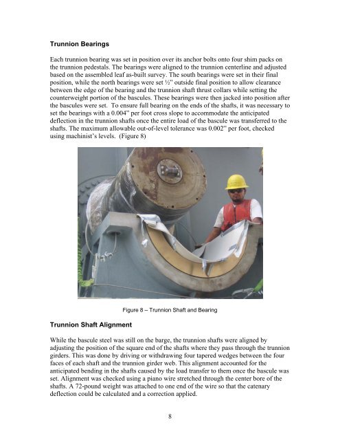
Trunnion BearingsEach trunnion bearing was set in position over its anchor bolts onto four shim packs onthe trunnion pedestals. The bearings were aligned to the trunnion centerline <strong>and</strong> adjustedbased on the assembled leaf as-built survey. The south bearings were set in their finalposition, while the north bearings were set ½” outside final position to allow clearancebetween the edge <strong>of</strong> the bearing <strong>and</strong> the trunnion shaft thrust collars while setting thecounterweight portion <strong>of</strong> the <strong>bascules</strong>. These bearings were then jacked into position afterthe <strong>bascules</strong> were set. To ensure full bearing on the ends <strong>of</strong> the shafts, it was necessary toset the bearings with a 0.004” per foot cross slope to accommodate the anticipateddeflection in the trunnion shafts once the entire load <strong>of</strong> the bascule was transferred to theshafts. The maximum allowable out-<strong>of</strong>-level tolerance was 0.002” per foot, checkedusing machinist’s levels. (Figure 8)Trunnion Shaft AlignmentFigure 8 – Trunnion Shaft <strong>and</strong> BearingWhile the bascule steel was still on the barge, the trunnion shafts were aligned byadjusting the position <strong>of</strong> the square end <strong>of</strong> the shafts where they pass through the trunniongirders. This was done by driving or withdrawing four tapered wedges between the fourfaces <strong>of</strong> each shaft <strong>and</strong> the trunnion girder web. This alignment accounted for theanticipated bending in the shafts caused by the load transfer to them once the bascule wasset. Alignment was checked using a piano wire stretched through the center bore <strong>of</strong> theshafts. A 72-pound weight was attached to one end <strong>of</strong> the wire so that the catenarydeflection could be calculated <strong>and</strong> a correction applied.8


