Download PDF - WES Components
Download PDF - WES Components
Download PDF - WES Components
- No tags were found...

Create successful ePaper yourself
Turn your PDF publications into a flip-book with our unique Google optimized e-Paper software.
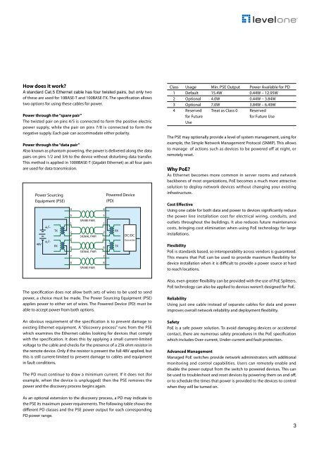
How does it work?A standard Cat.5 Ethernet cable has four twisted pairs, but only twoof these are used for 10BASE-T and 100BASE-TX. The specification allowstwo options for using these cables for power.Power through the “spare pair”The twisted pair on pins 4/5 is connected to form the positive electricpower supply, while the pair on pins 7/8 is connected to form thenegative supply. Each pair can accommodate either polarity.Power through the “data pair”Also known as phantom powering, the power is delivered along the datapairs on pins 1/2 and 3/6 to the device without disturbing data transfer.This method is applied in 1000BASE-T (Gigabit Ethernet) as all four pairsare used for data transmission.Power SourcingEquipment (PSE)48V+/-+/-TXRX45123678SPARE PAIRSIGNAL PAIRSIGNAL PAIRSPARE PAIRPowered Device(PD)The specification does not allow both sets of wires to be used to sendpower, a choice must be made. The Power Sourcing Equipment (PSE)applies power to either set of wires. The Powered Device (PD) must beable to accept power from both options.An obvious requirement of the specification is to prevent damage toexisting Ethernet equipment. A “discovery process” runs from the PSEwhich examines the Ethernet cables looking for devices that complywith the specification. It does this by applying a small current-limitedvoltage to the cable and checks for the presence of a 25k ohm resistor inthe remote device. Only if the resistor is present the full 48V applied, butthis is still current-limited to prevent damage to cables and equipmentin fault conditions.The PD must continue to draw a minimum current. If it does not (forexample, when the device is unplugged) then the PSE removes thepower and the discovery process begins again.45123678RXTXDC/DCConverterClass Usage Min. PSE Output Power Available for PD1 Default 15.4W 0.44W – 12.95W2 Optional 4.0W 0.44W – 3.84W3 Optional 7.0W 3.84W – 6.49W4 Reserved Treat as Class 0 Reservedfor Futurefor Future UseUseThe PSE may optionally provide a level of system management, using forexample, the Simple Network Management Protocol (SNMP). This allowsto manage of actions such as devices to be powered off at night, orremotely reset.Why PoE?As Ethernet becomes more common in server rooms and networkbackbones of most organizations, PoE becomes a much more attractivesolution to deploy network devices without changing your existinginfrastructure.Cost EffectiveUsing one cable for both data and power to devices significantly reducethe power line installation cost for electrical wiring, conduits, andoutlets throughout the buildings. It also reduces future maintenancecosts, bringing cost elimination when using PoE technology for largeinstallations.FlexibilityPoE is standards based, so interoperability across vendors is guaranteed.This means that PoE can be used to provide maximum flexibility fordevice installation when it is difficult to provide a power source at hardto reach locations.Also, even greater flexibility can be provided with the use of PoE Splitters,PoE technology can also be applied to devices weren’t designed for PoE.ReliabilityUsing just one cable instead of separate cables for data and powerimproves overall network reliability and deployment flexibility.SafetyPoE is a safe power solution. To avoid damaging devices or accidentalcontact, there are numerous safety procedures in the PoE specificationwhich includes Over-current, Under-current and fault protection.Advanced ManagementManaged PoE switches provide network administrators with additionalmonitoring and control capabilities. Users can remotely enable anddisable the power output from the switch to powered devices. This canbe used to troubleshoot and reset devices by powering them on and off,or to schedule the times that power is provided to the devices to controlwhen they will be turned on.As an optional extension to the discovery process, a PD may indicate tothe PSE its maximum power requirements. The following table shows thedifferent PD classes and the PSE power output for each correspondingPD power range.3