SuperDuct Four-Wire Duct Smoke Detector - UTCFS Global Security ...
SuperDuct Four-Wire Duct Smoke Detector - UTCFS Global Security ...
SuperDuct Four-Wire Duct Smoke Detector - UTCFS Global Security ...

Create successful ePaper yourself
Turn your PDF publications into a flip-book with our unique Google optimized e-Paper software.
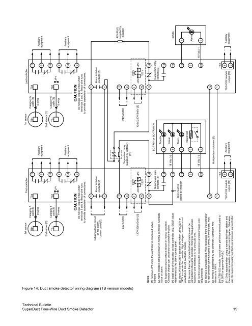
1st sensorCategory 5TB1cable [8]TB4First controller 1st sensorLast controllerCategory 517TB1cable [8]TB4178 wires6Auxiliaryequipment8 wires62nd sensor [1]TB1Category 5cable [8]8 wiresTB2JP11672nd sensor [1]TB1Category 5cable [8]8 wiresTB2JP116718Auxiliaryequipment18CAUTIONDo not use looped wires underterminals 5 and 4. Break wire runsto provide supervision of connections.8CAUTIONDo not use looped wires underterminals 5 and 4. Break wire runsto provide supervision of connections.8Initiating device circuiton fire alarmcontrol panel [7]+−54Alarm initiationcontacts [2]54Alarm initiationcontacts [2]24V AC/DC120V/220V/240V [5]−+109LN230VJP2 JP3120VSupervision relay(supplied by installer)[11]24V AC/DC120V/220V/240V [5]−+109LN230VJP2 JP3120 VNotes[1] Remove JP1 when the controller is connected to twosensors[2] Alarm initiation contacts shown in normal condition. Contactsclose on alarm.[3] Supervision relay contacts shown in normal condition.Contacts change over on sensor or controller trouble.[4] Install end-of-line resistor on last controller only. EOLR valuedetermined by fire alarm control panel.[5] Move JP3 to the 230V position only when using 220V or240V to operate the controller. High voltage connections notprovided on 24-volt controller models.[6] No more than two remote test/reset stations can beconnected to the same controller. Wiring is nonsupervised.Maximum wire resistance is 10 ohms per wire.[7] Control panel provides supervision and determines wirerequirements[8] Wiring is nonsupervised. <strong>Wire</strong> resistance from first controllerto last controller can not exceed 5 ohms.15 controllers, max.[9] Wiring is supervised by the controller. Maximum wiredistance is 100 ft.[10] TSD-C02 module has not been performance evaluated toUL 2075 or approved by ULC[11] Only required when using a remote test/reset station andthe controller is wired to a fire alarm control panel. Otherwise,use the supervision relay contacts as shown on last controller.3<strong>Wire</strong> must beadded by installer121TSD-CO2 moduleoutput [10]14Supervision relaycontacts [3]131915220TB31218 Vdc ( )Multiple fan shutdown [8]−++SD-TRK4 or SD-TRM4 [6]54132AuxiliaryequipmentTroublePowerAlarmReset/Test3121TSD-CO2 moduleoutput [10]14Supervision relaycontacts [3]18 Vdc ( − )18 Vdc ( − )131915220TB312−+AuxiliaryequipmentAuxiliaryequipmentEOLR [4](supplied byinstaller)5956A1Alarm2AuxiliaryequipmentFigure 14: <strong>Duct</strong> smoke detector wiring diagram (TB version models)Technical Bulletin<strong>Super<strong>Duct</strong></strong> <strong>Four</strong>-<strong>Wire</strong> <strong>Duct</strong> <strong>Smoke</strong> <strong>Detector</strong> 15