SuperDuct Four-Wire Duct Smoke Detector - UTCFS Global Security ...
SuperDuct Four-Wire Duct Smoke Detector - UTCFS Global Security ...
SuperDuct Four-Wire Duct Smoke Detector - UTCFS Global Security ...

Create successful ePaper yourself
Turn your PDF publications into a flip-book with our unique Google optimized e-Paper software.
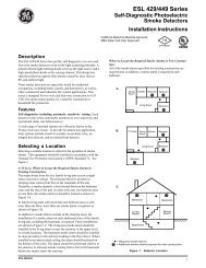
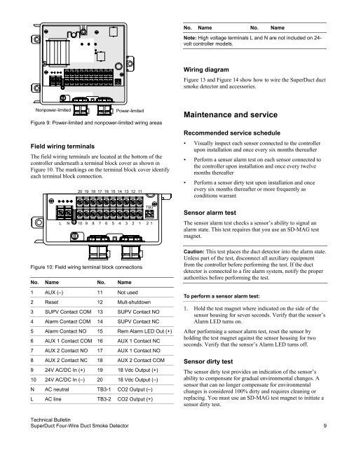
No. Name No. NameNote: High voltage terminals L and N are not included on 24-volt controller models.Wiring diagramFigure 13 and Figure 14 show how to wire the <strong>Super<strong>Duct</strong></strong> ductsmoke detector and accessories.Nonpower-limitedPower-limitedFigure 9: Power-limited and nonpower-limited wiring areasField wiring terminalsThe field wiring terminals are located at the bottom of thecontroller underneath a terminal block cover as shown inFigure 10. The markings on the terminal block cover identifyeach terminal block connection.20 19 18 17 16 15 14 13 12 11TB3L N 10 9 8 7 6 5 4 3 2 1 2 1Maintenance and serviceRecommended service schedule• Visually inspect each sensor connected to the controllerupon installation and once every six months thereafter• Perform a sensor alarm test on each sensor connected tothe controller upon installation and once every twelvemonths thereafter• Perform a sensor dirty test upon installation and onceevery six months thereafter or more frequently asconditions warrantSensor alarm testThe sensor alarm test checks a sensor’s ability to signal analarm state. This test requires that you use an SD-MAG testmagnet.Figure 10: Field wiring terminal block connectionsNo. Name No. Name1 AUX (–) 11 Not used2 Reset 12 Mult-shutdown3 SUPV Contact COM 13 SUPV Contact NO4 Alarm Contact COM 14 SUPV Contact NC5 Alarm Contact NO 15 Rem Alarm LED Out (+)6 AUX 1 Contact COM 16 AUX 1 Contact NC7 AUX 2 Contact NO 17 AUX 1 Contact NO8 AUX 2 Contact NC 18 AUX 2 Contact COM9 24V AC/DC In (+) 19 18 Vdc Output (+)10 24V AC/DC In (–) 20 18 Vdc Output (–)N AC neutral TB3-1 CO2 Output (–)L AC line TB3-2 CO2 Output (+)Caution: This test places the duct detector into the alarm state.Unless part of the test, disconnect all auxiliary equipmentfrom the controller before performing the test. If the ductdetector is connected to a fire alarm system, notify the properauthorities before performing the test.To perform a sensor alarm test:1. Hold the test magnet where indicated on the side of thesensor housing for seven seconds. Verify that the sensor’sAlarm LED turns on.After performing a sensor alarm test, reset the sensor byholding the test magnet against the sensor housing for twoseconds. Verify that the sensor’s Alarm LED turns off.Sensor dirty testThe sensor dirty test provides an indication of the sensor’sability to compensate for gradual environmental changes. Asensor that can no longer compensate for environmentalchanges is considered 100% dirty and requires cleaning orreplacing. You must use an SD-MAG test magnet to initiate asensor dirty test.Technical Bulletin<strong>Super<strong>Duct</strong></strong> <strong>Four</strong>-<strong>Wire</strong> <strong>Duct</strong> <strong>Smoke</strong> <strong>Detector</strong> 9