CM-021-GB-II 10/100/1000Base-T to 1000Base-FX Switch ...
CM-021-GB-II 10/100/1000Base-T to 1000Base-FX Switch ...
CM-021-GB-II 10/100/1000Base-T to 1000Base-FX Switch ...

Create successful ePaper yourself
Turn your PDF publications into a flip-book with our unique Google optimized e-Paper software.
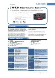
Lantech<strong>CM</strong>-<strong>021</strong>-<strong>GB</strong>-<strong>II</strong><strong>10</strong>/<strong>10</strong>0/<strong>10</strong>00Base-T <strong>to</strong> <strong>10</strong>00Base-<strong>FX</strong> <strong>Switch</strong> ConverterUser GuideRev.1.01Aug 2008
Revision His<strong>to</strong>ry<strong>10</strong>/<strong>10</strong>0/<strong>10</strong>00Base-T <strong>to</strong> <strong>10</strong>00Base-<strong>FX</strong> <strong>Switch</strong> ConverterDocumentReleaseDate Revision Initials1.00 Aug 18, 2008 First release E.C.1.01 Sep 11, 2008Add dimension picture and modify thepower consumption valueE.C.i
ContentIntroduce ....................................................................................................................... 1FEATURES ..................................................................................................................................... 2PACKAGE CONTENTS .................................................................................................................... 4Hardware Description ................................................................................................... 5FRONT PANEL ............................................................................................................................... 6REAR PANEL ................................................................................................................................. 6PORTS ........................................................................................................................................... 7LED INDICATORS .......................................................................................................................... 7DIP-SWITCH .................................................................................................................................. 8Converters module Installation ................................................................................... <strong>10</strong>CABLING ..................................................................................................................................... 11Troubles shooting ....................................................................................................... 12ii
Introduce• The Giga Fiber Converter has two types of module package; one is stand aloneconverter module. And another one is mounted in converter chassis convertermodule.• The Giga Fiber Converter is a cost- effective solution for the converting<strong>10</strong>/<strong>10</strong>0/<strong>10</strong>00Base-TX (Au<strong>to</strong> MDI/MDIX) and pure <strong>10</strong>00 Base-T <strong>to</strong> <strong>10</strong>00Base-<strong>FX</strong>cabling. It can be slotted in Multi-Converter Chassis on up <strong>to</strong> <strong>10</strong> optional modularconverter units, which allows your network connectivity <strong>to</strong> be more flexible. It alsocan use stand-alone without slot in Multi-Converter Chassis.• The Giga Fiber Converter will allow you <strong>to</strong> extend the cabling distance of your<strong>10</strong>/<strong>10</strong>0/<strong>10</strong>00BaseTX (Au<strong>to</strong> MDI/MDIX) or pure <strong>10</strong>00 Base-T network up <strong>to</strong> 550mfor multi-mode fiber or <strong>10</strong> kilometers for single-mode fiber. The Giga FiberConverter gives you the option <strong>to</strong> choose from the most popular fiber cablingconnec<strong>to</strong>rs: SC multi- mode fiber connec<strong>to</strong>r and SC single-mode fiber connec<strong>to</strong>r.The Modular Giga Fiber Converters provides you with one Fiber connec<strong>to</strong>r foryour fiber optic cable and one Ethernet RJ-45 port (Au<strong>to</strong> MDI/MDIX) for your<strong>10</strong>/<strong>10</strong>0/<strong>10</strong>00BaseTX copper cable or pure <strong>10</strong>00 Base-T copper cable connection.There are DIP- switches <strong>to</strong> set the operation mode for UTP, Fiber ports and linklost forwarding function.1
FeaturesStandardIEEE 802.3 <strong>10</strong>BASE-TIEEE 802.3u <strong>10</strong>0BASE-TXIEEE 802.3ab <strong>10</strong>00BaseT,IEEE 802.3z <strong>10</strong>00BaseSX/LX standardsIEEE 802.3x Flow Control and Back pressureLED Indica<strong>to</strong>rsPower (Green)UTP SPD: <strong>10</strong>00Mbps /<strong>10</strong>0MbpsLnk/Act: UTP /FIBERFDX: UTP: Full-Duplex mode / Half-Duplex or Link downFIBER: Full-Duplex mode / Link downConnec<strong>to</strong>rFiber: Duplex SC/MINI <strong>GB</strong>IC 3.3V/ WDMRJ-45 Socket: CAT-5e (<strong>10</strong>/<strong>10</strong>0/<strong>10</strong>00Mbps) Twisted Paircable Au<strong>to</strong> MDI/MDI-X and Au<strong>to</strong>-Negotiation FunctionSupportFiberparametersFiber Core: Multi-Mode (62.5/125um, 50/125um)Single-Mode (9/125um)Wavelength: 850nm(Multi-mode),13<strong>10</strong>nm(Single-mode)/13<strong>10</strong>nm(WDM, TX),1550nm(WDM, RX)Fiber Distance: 550M (Multi-Mode Fiber)<strong>10</strong> KM (Single-Mode Fiber)WDM (Single-mode) <strong>10</strong>KM, 20KMLink LoseForwardCopperFiber: If copper port link down, then mediaconverter will forced fiber <strong>to</strong> link down.FiberCopper: If Fiber port link down, the media converterwill forced copper port <strong>to</strong> link down.2
<strong>Switch</strong>architectureS<strong>to</strong>re and ForwardJumbo Frame16Kbyte(Pure converter mode)/2Kbyte(<strong>Switch</strong> converter mode)Power Stand-alone (external adapter):DC 9V / 0.7APowerConsumption4.3 Watts(max)OperatingTemperatureO℃ <strong>to</strong> 45℃ (32℉ <strong>to</strong> 113℉)OperatingHumidity<strong>10</strong>% <strong>to</strong> 90%S<strong>to</strong>rageenvironment-40℃~70℃S<strong>to</strong>rageHumidity<strong>10</strong>% <strong>to</strong> 90%Dimensions120mm x 85mm x 26mmEMIFCC Class A,CE3
Package ContentsBeware of which type of converter module that you have purchased. And, please refer<strong>to</strong> the package content list below <strong>to</strong> verify them against the checklist.• Stand-alone converter module package contains following items.‣ The Giga Fiber Converter‣ AC-DC Power Adapter‣ User Guide‣ Rack mount ear (only for converter chassis)Compare the contents of your Converter with the standard checklist above. If any itemis damaged or missing, please contact your local dealer for service.4
Hardware DescriptionThe Giga Fiber Converter dimension (L x W x H): 120mm x 85mm x 26mm5
Front Panel• <strong>10</strong>/<strong>10</strong>0/<strong>10</strong>00Base-T <strong>to</strong> <strong>10</strong>00Base-<strong>FX</strong> converter module• The Front Panel of the <strong>10</strong>/<strong>10</strong>0/<strong>10</strong>00Base-T <strong>to</strong> <strong>10</strong>00Base-<strong>FX</strong> converter moduleconsists of one Giga Fiber port, one copper Port (Au<strong>to</strong> MDI/MDIX), and 6 LEDIndica<strong>to</strong>rs (SPD, LK/ACT, FDX, Fiber LK/ACT, FDX/COL, and PWR).1324(1) RJ-45 Port (3) DIP-<strong>Switch</strong>(2) LED (4) Fiber Connec<strong>to</strong>rRear PanelThe rear panel contains a power socket. This power socket accepts DC9V voltage andminimum 0.7A supplied current.DC IN6
Ports• Copper Port (Au<strong>to</strong> MDI/MDIX) of <strong>10</strong>/<strong>10</strong>0/<strong>10</strong>00Base-T <strong>to</strong> <strong>10</strong>00Base-<strong>FX</strong> convertermodule: The Ethernet ports will au<strong>to</strong>-sense for <strong>10</strong>Base-T, <strong>10</strong>0Base-TX, or<strong>10</strong>00Base-T connections. Au<strong>to</strong> MDI/MDIX means that you can connect <strong>to</strong> another<strong>Switch</strong> or workstation without changing non-crossover or crossover cabling.• Fiber Port: This port is for <strong>10</strong>00Base-<strong>FX</strong> connections. We provide different styles offiber connec<strong>to</strong>rs (SC/SC single-mode) <strong>to</strong> meet your needs.LED Indica<strong>to</strong>rsThere are 6 diagnostic LEDs located on the Front panel of converter module. Theyprovide real-time information of system and optional status. The following tableprovides description of the LED status and their meanings for Modular Giga FiberConverter.• <strong>10</strong>/<strong>10</strong>0/<strong>10</strong>00Base-T <strong>to</strong> <strong>10</strong>00Base-<strong>FX</strong> converter moduleLED Status MeaningPWR Green Power onSPDLNK/ACT(UTP)GreenAmberOFFGreenBlinksOff<strong>10</strong>00Mbps UTP Speed<strong>10</strong>0Mbps UTP Speed<strong>10</strong>Mbps UTP SpeedLink upTransmittingLink downFDX (UTP) Amber Full-duplex mode7
OffHalf-duplex mode or link downLNK/ACT(Fiber)GreenBlinksOffLink upTransmittingLink downFDX/COL (Fiber)AmberOffFull-duplex modeLink downDIP-switchThe DIP-switch is used <strong>to</strong> configure operation mode for LLF (Link Lost Forwarding)and operation mode for Copper/Fiber port. The default value of Dipswitch is OFF.• <strong>10</strong>/<strong>10</strong>0/<strong>10</strong>00Base-T <strong>to</strong> <strong>10</strong>00Base-<strong>FX</strong> converter moduleS/W No Status Description123ONOFFONOFFONOFFLLF EnableLLF DisablePure converter mode<strong>Switch</strong> converter modeReservedReservedLink Lost Forwarding: When LLF is enabled, it will allow copper port link failure <strong>to</strong> bereported <strong>to</strong> the Fiber side and also allow Fiber link failure <strong>to</strong> be reported <strong>to</strong> the copperside. Therefore, a link loss forward feature is provided in both copper and Fiber side.Pure Converter mode: When pure converter mode is enabling (on), it operates withthe minimum latency. The transmission flow does not wait until entire frame is ready,but instead it forwards the received data immediately after the data being received.8
And TP port should be forced at <strong>10</strong>00M in this application. When DIP-<strong>Switch</strong> is in<strong>Switch</strong> Converter mode (off), the converter function is same as <strong>Switch</strong> Hub.[Note]a) Please don’t change the DIP-switch setting when copper or fiber port is transmittingor receiving data. It may cause some data error.b) Please power off then power on when you change the DIP-switch setting.9
Converters module InstallationThis installation is only for mounted in converter chassis converter module. You canfollow the steps below <strong>to</strong> install modular converters.A. Remove the blank bracket by rotating thumbscrew counterclockwise. Put the blankbracket aside, but don’t discard blanket bracket.B. Open the rack mount ear kit. The kit contains two-rack mount ear (with thumbscrew)and four screws.C. Attach rack mount ear on both sides of the modular converter by using ascrewdriver <strong>to</strong> secure the rack mount ears.D. Install the modular converter by inserting it in<strong>to</strong> the guides and sliding it in until its<strong>to</strong>ps. Press it firmly until the power plug in the chassis plugs in<strong>to</strong> the modularconverter receptacle. Slide the modular converter in smoothly.E. Gently push the thumbscrews in and turn clockwise <strong>to</strong> tighten. Do not over tightenthe thumbscrews.<strong>10</strong>
Cabling• Using four twisted-pair, Category 5e cabling for copper port connection. The cablebetween the converter and the link partner (switch, hub, workstation, etc.) must beless than <strong>10</strong>0 meters (328 ft.) long.• Fiber segment using single-mode connec<strong>to</strong>r type must use 9/125 μmsingle-mode fiber cable. You can connect two devices in the distance of <strong>10</strong>Kilometers in full duplex operation. For half-duplex operation, the recommendedmaximum distance is 412 meters (1,352 ft.)• Fiber segment using multi-mode connec<strong>to</strong>r type must use 50 or 62.5/125 ummulti-mode fiber cable. You can connect two devices up <strong>to</strong> 550m distances.11
Troubles shooting• Check the configuration DIP-switch. It must be setting in the same operationmode with the link partner.• Select the proper Copper/Fiber cable <strong>to</strong> construct your network. The single-modeconverter must use single-mode fiber cable. Please check that you are using theright cable.• Don’t both use multi-mode and single mode.12