IGC-0101GB 10/100/1000T to Mini-GBIC Industrial Switch Converter ...
IGC-0101GB 10/100/1000T to Mini-GBIC Industrial Switch Converter ...
IGC-0101GB 10/100/1000T to Mini-GBIC Industrial Switch Converter ...

Create successful ePaper yourself
Turn your PDF publications into a flip-book with our unique Google optimized e-Paper software.
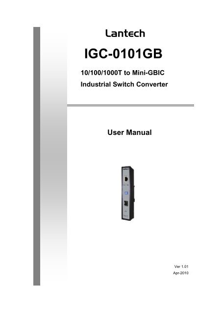
Lantech<strong>IGC</strong>-<strong>0<strong>10</strong>1GB</strong><strong>10</strong>/<strong>10</strong>0/<strong>10</strong>00T <strong>to</strong> <strong>Mini</strong>-<strong>GBIC</strong><strong>Industrial</strong> <strong>Switch</strong> <strong>Converter</strong>User ManualVer 1.01Apr-20<strong>10</strong>
ContentOverview ............................................................ 1Introduction .............................................................. 1Features ................................................................... 3Packing List .............................................................. 4Safety Precaution ..................................................... 4Hardware Description ......................................... 5Front Panel ............................................................... 5Top View .................................................................. 6Wiring the Power Inputs ........................................... 6Wiring the Fault Alarm Contact ................................ 7LED Indica<strong>to</strong>rs .......................................................... 8DIP-<strong>Switch</strong> ............................................................... 9Ports ....................................................................... <strong>10</strong>Cabling ................................................................... 11Mounting Installation ........................................ 15DIN-Rail Mounting .................................................. 15Wall Mount Plate Mounting .................................... 17
Hardware Installation ....................................... 18Installation Steps .................................................... 18Troubles shooting ............................................. 20Technical Specification .................................... 21
FCC WarningThis Equipment has been tested and found <strong>to</strong> comply with the limits for a Class-A digitaldevice, pursuant <strong>to</strong> Part 15 of the FCC rules. These limits are designed <strong>to</strong> providereasonable protection against harmful interference in a residential installation. Thisequipment generates, uses, and can radiate radio frequency energy. It may causeharmful interference <strong>to</strong> radio communications if the equipment is not installed and used inaccordance with the instructions. However, there is no guarantee that interference willnot occur in a particular installation. If this equipment does cause harmful interference <strong>to</strong>radio or television reception, which can be determined by turning the equipment off andon, the user is encouraged <strong>to</strong> try <strong>to</strong> correct the interference by one or more of thefollowing measures:• Reorient or relocate the receiving antenna.• Increase the separation between the equipment and receiver.• Connect the equipment in<strong>to</strong> an outlet on a circuit different from that <strong>to</strong> which thereceiver is connected.• Consult the dealer or an experienced radio/TV technician for help.CE Mark WarningThis is a Class-A product. In a domestic environment this product may cause radiointerference in which case the user may be required <strong>to</strong> take adequate measures.
Flexible Mounting<strong>10</strong>/<strong>10</strong>0/<strong>10</strong>00TX <strong>to</strong> MINI-<strong>GBIC</strong> <strong>Industrial</strong> <strong>Switch</strong> <strong>Converter</strong> is compactand can be mounted on a DIN-rail or a panel, so it is suitable for anyspace-constrained environment.Advanced ProtectionThe power line of <strong>10</strong>/<strong>10</strong>0/<strong>10</strong>00TX <strong>to</strong> MINI-<strong>GBIC</strong> <strong>Industrial</strong> <strong>Switch</strong><strong>Converter</strong> supports up <strong>to</strong> 3,000 V DC EFT protection, which secureequipment against unregulated voltage and make systems safer andmore reliable. Meanwhile, 6,000 V DC ESD protections for Ethernet portsmake the industrial switch converter more suitable for harshenvironments.Wide Operating TemperatureThe operating temperature of the <strong>10</strong>/<strong>10</strong>0/<strong>10</strong>00TX <strong>to</strong> MINI-<strong>GBIC</strong><strong>Industrial</strong> <strong>Switch</strong> <strong>Converter</strong> is between -40 ~ 75 o C (wide operatingtemperature model) or -20 ~ 60 o C (standard model). With such a widerange, you can use the industrial switch converter in some of theharshest industrial environments that exist.Easy TroubleshootingLED indica<strong>to</strong>rs make troubleshooting quick and easy. The <strong>10</strong>/<strong>10</strong>0/<strong>10</strong>00Base-TX port has 2 LEDs that display the link status, whether the port isworking at <strong>10</strong>00M transmission speed or not. Also the three powerindica<strong>to</strong>rs P1, P2 and Fault help you diagnose immediately.2
Features• Provides 1 x SFP (mini-<strong>GBIC</strong>) type socket (<strong>10</strong>/<strong>10</strong>0/<strong>10</strong>00TX <strong>to</strong>MINI-<strong>GBIC</strong> model)• Provides 1 x <strong>10</strong>/<strong>10</strong>0/<strong>10</strong>00Mbps Ethernet ports with RJ-45 connec<strong>to</strong>r• Supports full/half duplex flow control• Supports MDI/MDI-X au<strong>to</strong>-crossover• Supports surge (EFT) protection 3,000 V DC for power line• Supports 6,000 V DC Ethernet ESD protection• Embedded with a switch controller, supports au<strong>to</strong>-negotiation• Supports s<strong>to</strong>re & forward transmission• Supports redundant +9 ~ 56 V DC power input• Provides flexible mounting: DIN-rail, Wall Mounting• Supports operating temperatures from -40 ~ 75 o C (wide operatingtemperature model) or -20 ~ 60 o C (standard model)3
Packing List• 1 x <strong>10</strong>/<strong>10</strong>0/<strong>10</strong>00 <strong>to</strong> <strong>Mini</strong>-<strong>GBIC</strong> <strong>Industrial</strong> <strong>Switch</strong> <strong>Converter</strong>• 1 x User manual• 2 x Wall Mounting Bracket and ScrewsSafety PrecautionAttention IF DC voltage is supplied by an external circuit, please use aprotection device on the power supply input.4
Hardware DescriptionIn this paragraph, we will introduce the <strong>Industrial</strong> switch converter’shardware spec, port, cabling information, and wiring installation.Front PanelThe Front Panel of the <strong>10</strong>/<strong>10</strong>0/<strong>10</strong>00TX <strong>to</strong> MINI-<strong>GBIC</strong>/<strong>10</strong>/<strong>10</strong>0/<strong>10</strong>00TX<strong>Industrial</strong> <strong>Switch</strong> <strong>Converter</strong> is shown as below.Front Panel of the <strong>Industrial</strong> <strong>Switch</strong> <strong>Converter</strong>5
Top ViewThe <strong>to</strong>p panel of the <strong>Industrial</strong> <strong>Switch</strong> <strong>Converter</strong> is equipped oneterminal block connec<strong>to</strong>r of two DC power inputs.Top panel of the <strong>Industrial</strong> <strong>Switch</strong> <strong>Converter</strong>Wiring the Power InputsPlease follow the steps below <strong>to</strong> insert the power wire.1. Insert the positive and negative wires in<strong>to</strong> the V+ and V- contacts on theterminal block connec<strong>to</strong>r.6
2. To tighten the wire-clamp screws for preventing the DC wires <strong>to</strong> loose.Wiring the Fault Alarm ContactThe fault alarm contact is in the middle of terminal block connec<strong>to</strong>r as thepicture shows below. Inserting the wires, it will detect the fault statuswhich the power is failure or port link failure (for managed model) and forman open circuit.Insert the wires in<strong>to</strong> the fault alarm contact (No. 3 & 4)NoteThe wire gauge for the terminal block should be in the rangebetween 12~ 24 AWG.7
LED Indica<strong>to</strong>rsThere are few LEDs display the power status and network statuslocated on the front panel of the <strong>Industrial</strong> switch converter, each ofthem has its own specific meaning as below table.Table 2.1: <strong>Industrial</strong> <strong>Switch</strong> <strong>Converter</strong> LED DefinitionLED Color DescriptionP1GreenOn Power input 1 is activeOff Power input 1 is inactiveP2GreenOn Power input 2 is activeOff Power input 2 is inactiveOn Power input 1 or 2 has failedFault RedPower input 1 and 2 are both functional,Offor no power inputOn Connected <strong>to</strong> networkLNK/ACTGreen Flashing Networking is active(fiber port)Off Not connected <strong>to</strong> networkOn Link <strong>to</strong> <strong>10</strong>00M bps network<strong>10</strong>00MYellowNot connected <strong>to</strong> network or not working(RJ-45)Offat speed of <strong>10</strong>00MOn Connected <strong>to</strong> networkLNK/ACTGreen Flashing Networking is active(RJ-45)Off Not connected <strong>to</strong> network8
DIP-<strong>Switch</strong>The DIP-<strong>Switch</strong> is used <strong>to</strong> configure operation mode for LLF (Link LostForwarding) and power alarm. The default value of DIP-switch is OFF.Table 2.2: <strong>Industrial</strong> <strong>Switch</strong> <strong>Converter</strong> DIP-<strong>Switch</strong> DefinitionS/W No StatusON1OFFON2OFFDescriptionEnable Power AlarmDisable Power AlarmEnables LLFDisables LLFLink Lost Forwarding (DIP-<strong>Switch</strong> 2): When LLF is enabled, it allowsUTP link failures <strong>to</strong> be reported <strong>to</strong> the fiber side and also allows Fiberlink failures <strong>to</strong> be reported <strong>to</strong> the UTP side. Therefore, a link lossforwarding feature is provided in both UTP and Fiber side.NoteWhen SW 2 is on, once the fiber or UTP/STP cable isdisconnected, the LNK/ACT LED off. When the cable isreconnected, the LNK/ACT LED blinks for 2 ~ 6 seconds whichmeans the connection is recovering from failure.NotePlease don’t change the DIP-switch setting when UTP/STP orfiber port is transmitting or receiving data. It may cause some dataerror. Besides, if you change the DIP-switch setting, please poweroff the converter and power on again <strong>to</strong> make the setting effective.9
PortsRJ-45 ports (Au<strong>to</strong> MDI/MDIX): The RJ-45 ports are au<strong>to</strong>-sensing for<strong>10</strong>Base-T, <strong>10</strong>0Base-TX or <strong>10</strong>00Base-T devices connections. Au<strong>to</strong>MDI/MDIX means that you can connect <strong>to</strong> another switch or workstationwithout changing straight through or crossover cabling. See figures asbelow for straight through and crossover cable schematic.• RJ-45 Pin AssignmentsPin NumberAssignment1 Tx+2 Tx-3 Rx+6 Rx-Note“+” and “-” signs represent the polarity of the wires that make upeach wire pair.All ports on this industrial switch converter support au<strong>to</strong>maticMDI/MDI-X operation, you can use straight-through cables (See Figurebelow) for all network connections <strong>to</strong> PCs or servers, or <strong>to</strong> otherswitches or hubs. In straight-through cable, pins 1, 2, 3, and 6, at oneend of the cable, are connected straight through <strong>to</strong> pins 1, 2, 3 and 6 atthe other end of the cable. The table below shows the <strong>10</strong>BASE-T/<strong>10</strong>0BASE-TX /<strong>10</strong>00Base-T MDI and MDI-X port pin outs.Pin MDI-X Signal Name MDI Signal Name1 Receive Data plus (RD+) Transmit Data plus (TD+)2 Receive Data minus (RD-) Transmit Data minus (TD-)3 Transmit Data plus (TD+) Receive Data plus (RD+)6 Transmit Data minus (TD-) Receive Data minus (RD-)<strong>10</strong>
Straight Through Cable SchematicCross Over Cable SchematicCablingTwisted-pair segment can use unshielded twisted pair (UTP) orshielded twisted pair (STP) cabling. The cable between the link partner(switch, hub, workstation, etc.) and the converter must be less than <strong>10</strong>0meters (328 ft.) long and comply with the IEEE 802.3ab <strong>10</strong>00Base-Tstandard for Category 5e or above.Fiber segment using single-mode connec<strong>to</strong>r type must use 9/125μmsingle-mode fiber cable. You can connect two devices in the distance of<strong>10</strong> km. Fiber segment using multi-mode connec<strong>to</strong>r type must use50/125 or 62.5/125μm multi-mode fiber cable. You can connect twodevices up <strong>to</strong> 550m distances.The small form-fac<strong>to</strong>r pluggable (SFP) is a compact optical transceiverused in optical communications for both telecommunication and datacommunication applications.To connect the transceiver and LC cable, please follow the steps shownbelow:First, insert the transceiver in<strong>to</strong> the SFP module. Notice that the trianglemark is the bot<strong>to</strong>m of the module.11
Figure 2.8: Transceiver <strong>to</strong> the SFP moduleFigure 2.9: Transceiver Inserted12
Second, insert the fiber cable of LC connec<strong>to</strong>r in<strong>to</strong> the transceiver.Figure 2.<strong>10</strong>: LC connec<strong>to</strong>r <strong>to</strong> the transceiverTo remove the LC connec<strong>to</strong>r from the transceiver, please follow the stepsshown below:First, press the upper side of the LC connec<strong>to</strong>r from the transceiver and pull i<strong>to</strong>ut <strong>to</strong> release.Figure 2.11: Remove LC connec<strong>to</strong>r13
Second, push down the metal loop and pull the transceiver out by the plasticpart.Figure 2.12: Pull out from the SFP module14
Mounting InstallationDIN-Rail MountingThe DIN-Rail is screwed on the industrial switch when out of fac<strong>to</strong>ry. Ifthe DIN-Rail is not screwed on the industrial switch, please see thefollowing figure <strong>to</strong> screw the DIN-Rail on the switch. Follow the belowsteps <strong>to</strong> hang the industrial switch.1. Use the screws <strong>to</strong> screw on the DIN-Rail on the industrial switch2. To remove the DIN-Rail, reverse the step 1.15
3. First, insert the <strong>to</strong>p of DIN-Rail in<strong>to</strong> the track.4. Then, lightly push the but<strong>to</strong>n of DIN-Rail in<strong>to</strong> the track.5. Check the DIN-Rail is tightly on the track.6. To remove the industrial switch from the track, reverse steps above.16
Wall Mount Plate MountingFollow the steps below <strong>to</strong> mount the industrial switch with wall mount plate.1. Remove the DIN-Rail from the industrial switch; loose the screws <strong>to</strong>remove the DIN-Rail.2. Place the wall mount plate on the rear panel of the industrial switch.3. Use the screws <strong>to</strong> screw the wall mount plate on the industrial switch.4. Use the hook holes at the corners of the wall mount plate <strong>to</strong> hang theindustrial switch on the wall.5. To remove the wall mount plate, reverse steps above.17
Hardware InstallationIn this paragraph, we will describe how <strong>to</strong> install the 5-port<strong>10</strong>/<strong>10</strong>0/<strong>10</strong>00Base-TX <strong>Industrial</strong> <strong>Switch</strong> converter and the installation points forthe attention.Installation Steps1. Unpacked the <strong>Industrial</strong> switch converter packing.2. Check the DIN-Rail is screwed on the <strong>Industrial</strong> switch converter. If theDIN-Rail is not screwed on the <strong>Industrial</strong> switch converter. Please refer <strong>to</strong>DIN-Rail Mounting section for DIN-Rail installation. If you want <strong>to</strong> wallmount the <strong>Industrial</strong> switch converter, then please refer <strong>to</strong> Wall MountPlate Mounting section for wall mount plate installation.3. To hang the <strong>Industrial</strong> switch converter on the DIN-Rail track or wall,please refer <strong>to</strong> the Mounting Installation section.18
4. Power on the <strong>Industrial</strong> switch converter. How <strong>to</strong> wire the power; pleaserefer <strong>to</strong> the Wiring the Power Inputs section. The power LED on the<strong>Industrial</strong> switch converter will light up. Please refer <strong>to</strong> the LED Indica<strong>to</strong>rssection for meaning of LED lights.5. Prepare the twisted-pair, straight through Category 5 cable for Ethernetconnection.6. Insert one side of Category 5e or above cables in<strong>to</strong> the <strong>Industrial</strong> switchconverter Ethernet port (RJ-45 port) and another side of category 5e orabove cables <strong>to</strong> the network devices’ Ethernet port (RJ-45 port), e.g.switch, PC or Server. The UTP port (RJ-45) LED on the <strong>Industrial</strong> switchconverter will light up when the cable connected with the network device.Please refer <strong>to</strong> the LED Indica<strong>to</strong>rs section for LED light meaning.NoteBe sure the connected network devices support MDI/MDI-X. If it doesnot support, then use the crossover category 5e/above cable.7. When all connections are all set and LED lights all show in normal, theinstallation is complete.19
Technical SpecificationThe technical specifications of the <strong>Industrial</strong> <strong>Switch</strong> <strong>Converter</strong> are listed asfollows.CommunicationsStandardLANTransmission DistanceTransmission SpeedIEEE 802.3, 802.3ab, 802.3u, 802.3x,802.3z<strong>10</strong>/<strong>10</strong>0/<strong>10</strong>00Base-TXSFP (mini-<strong>GBIC</strong>) Fiber: Up <strong>to</strong> 1<strong>10</strong>kmEthernet: Up <strong>to</strong> <strong>10</strong>0 meters (STP or UTP)Up <strong>to</strong> <strong>10</strong>00 MbpsInterfaceConnec<strong>to</strong>rsLED Indica<strong>to</strong>rs1 x SFP (mini-<strong>GBIC</strong>) fiber socket1 x RJ-456-pin removable screw terminal(power & relay)TX port: <strong>10</strong>00M, LNK/ACTFiber port: LNK/ACTP1, P2, FaultPowerPower ConsumptionPower InputFault Output<strong>10</strong>/<strong>10</strong>0/<strong>10</strong>00TX <strong>to</strong> <strong>Mini</strong>-<strong>GBIC</strong> model:5.28 W2 x Unregulated +9 ~ 56 V DC1 Relay Output21
MechanismDimensions (WxDxH)EnclosureMounting30 x 95 x 140 mmIP30, Metal shell with solid mounting kitsDIN-rail, wallProtectionESD (Ethernet)6,000 V DCSurge (EFT for power)3,000 V DCReverse PolarityPresentOverload 0.9A@12V DC (25 o C)EnvironmentOperating TemperatureS<strong>to</strong>rage TemperatureOperating HumidityS<strong>to</strong>rage HumidityStandard model: -20 ~ 60 o CWide temp. model: -40 ~ 75 o C-40 ~ 85 o C5 ~ 95% (non-condensing)0 ~ 95% (non-condensing)CertificationsSafetyEMCUL, cUL, CE/EN-60950-1Class 1 / Division 2FCC Class ACE EN6<strong>10</strong>00-4-2 (ESD)CE EN6<strong>10</strong>00-4-3 (RS)CE EN-6<strong>10</strong>00-4-4 (EFT)CE EN6<strong>10</strong>00-4-5 (Surge)22
Free FallShockVibrationCE EN6<strong>10</strong>00-4-6 (CS)CE EN6<strong>10</strong>00-4-8CE EN6<strong>10</strong>00-4-11CE EN6<strong>10</strong>00-4-12CE EN6<strong>10</strong>00-6-2CE EN6<strong>10</strong>00-6-4IEC60068-2-32IEC60068-2-27IEC60068-2-623