System configuration - Lantech Communications Global Inc
System configuration - Lantech Communications Global Inc
System configuration - Lantech Communications Global Inc

You also want an ePaper? Increase the reach of your titles
YUMPU automatically turns print PDFs into web optimized ePapers that Google loves.
Login in the Console Interface ............................... 24CLI Management ................................................... 25Commands Level ............................................................ 26Commands Set List......................................................... 27<strong>System</strong> Commands Set .................................................. 27Port Commands Set ........................................................ 30Trunk Commands Set ..................................................... 32VLAN Commands Set ..................................................... 34Spanning Tree Commands Set ....................................... 35QOS Commands Set ...................................................... 38IGMP Commands Set ..................................................... 39Mac / Filter Table Commands Set ................................... 39SNMP Commands Set .................................................... 40Port Mirroring Commands Set ......................................... 42802.1x Commands Set ................................................... 43TFTP Commands Set ..................................................... 45<strong>System</strong>Log, SMTP and Event Commands Set ................ 46SNTP Commands Set ..................................................... 48Pro-ring Commands Set ................................................. 49Web-Based Management ........................................ 51About Web-based Management ............................ 51Preparing for Web Management ............................ 51<strong>System</strong> Login ......................................................... 52Main Page .............................................................. 53<strong>System</strong> Information ................................................ 54IP Configuration ..................................................... 54DHCP Server – <strong>System</strong> <strong>configuration</strong> .................... 55
DHCP Client – Client Entries ................................. 56DHCP Server - Port and IP Bindings ..................... 57TFTP - Update Firmware ....................................... 57TFTP – Restore Configuration ............................... 58TFTP - Backup Configuration ................................ 58<strong>System</strong> Event Log – Syslog Configuration ............. 59<strong>System</strong> Event Log - SMTP Configuration .............. 60<strong>System</strong> Event Log - Event Configuration ............... 61Fault Relay Alarm .................................................. 63SNTP Configuration ............................................... 64IP Security .............................................................. 67User Authentication ................................................ 68Port Statistics ......................................................... 69Port Control ............................................................ 70Port Trunk .............................................................. 71Aggregator setting .......................................................... 71Aggregator Information ................................................... 73State Activity ................................................................... 74Port Mirroring ......................................................... 74Rate Limiting .......................................................... 75VLAN <strong>configuration</strong> ................................................ 76VLAN <strong>configuration</strong> - Port-based VLAN .......................... 77802.1Q VLAN .................................................................. 80Rapid Spanning Tree ............................................. 83RSTP - <strong>System</strong> Configuration ......................................... 83RSTP - Port Configuration .............................................. 84
SNMP Configuration .............................................. 85<strong>System</strong> Configuration ...................................................... 86Trap Configuration .......................................................... 87SNMPV3 Configuration ................................................... 88QoS Configuration ................................................. 91QoS Policy and Priority Type .......................................... 91Port Base Priority ............................................................ 93COS Configuration .......................................................... 93TOS Configuration .......................................................... 93IGMP Configuration ............................................... 93Pro-Ring <strong>System</strong> .................................................... 95802.1X/Radius Configuration .......................................... 98MAC Address Table ...................................................... 101Factory Default ..................................................... 104Save Configuration .............................................. 104<strong>System</strong> Reboot .................................................... 104Troubles shooting ................................................. 106Technical Specification ......................................... 107
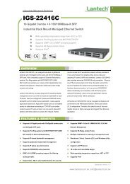
IntroductionThe 6 10/100/1000T + 2 10/100/1000T/Dual Speed SFP Combo w/ Pro-Ring ManagedIndustrial Switch is a cost-effective solution and meets the high reliability requirementsdemanded by industrial applications. The 6 10/100/1000T + 2 10/100/1000T/Dual SpeedSFP Combo w/ Pro-Ring Managed Industrial Switch can be easily managed through theWeb GUI. Using fiber port can extend the connection distance that increases thenetwork elasticity and performance. It also provides the Pro-Ring system that canprevent the network connection failure.Benefits• <strong>System</strong> Interface/Performance‣ RJ-45 ports support auto MDI/MDI-X function‣ SFP (Mini-GBIC) supports 100/1000 Dual Mode‣ Store-and-Forward switching architecture‣ Back-plane (Switching Fabric): 16Gbps‣ 1Mbits Packet Buffer‣ 8K MAC Address Table• Power Supply‣ Input Power Isolation design for Telcom application, Pass Hi-Pot test~1.5KV‣ Wide-range Redundant Power Design• VLAN‣ Port Based VLAN‣ Supports 802.1Q Tag VLAN‣ GVRP‣ Double Tag VLAN (Q in Q)*‣ Private VLAN**• Port Trunk with LACP• QoS (Quality of Service)‣ Supports IEEE 802.1p Class of Service‣ Per port provides 4 priority queues1
‣ Port Base, Tag Base and Type of Service Priority• Port Mirror: Monitor traffic in switched networks‣ TX Packet only‣ RX Packet only‣ Both of TX and RX Packet• Security‣ Port Security: MAC address entries/filter‣ IP Security: IP address security management to prevent unauthorized intruder‣ Login Security: IEEE 802.1X/RADIUS• IGMP with Query mode for Multi Media Application• Case/Installation‣ IP-30 Protection‣ DIN Rail and Wall Mount Design• Spanning Tree‣ Support IEEE 802.1d Spanning Tree‣ Support IEEE 802.1w Rapid Spanning Tree• Pro-ring‣ X-ring, Dual Homing, and Couple Ring Topology‣ Provide redundant backup feature and the recovery time below10ms• Bandwidth Control‣ Ingress Packet Filter and Egress Rate Limit‣ Broadcast/Multicast Packet Filter Control• <strong>System</strong> Event Log‣ <strong>System</strong> Log Server/Client‣ SMTP e-mail Alert‣ Relay Alarm Output <strong>System</strong> Events• SNMP Trap‣ Device cold start‣ Power status‣ Authentication failure‣ X-ring topology changed‣ Port Link up/Link down• TFTP Firmware Update and <strong>System</strong> Configuration Restore and Backup2
Package ContentsPlease refer to the package content list below to verify them against the checklist.• 6 10/100/1000T + 2 10/100/1000T/Dual Speed SFP Combo w/ Pro-Ring ManagedIndustrial Switch• User manual• RS-232/RJ-45 cable• Pluggable Terminal Block• 2 wall mount plates and 6 screws• One DIN-Rail (attached on the switch)6 10/100/1000T + 2 10/100/1000T/Dual Speed SFP Combo User Manualw/ Pro-Ring Managed Industrial SwitchRS-232-RJ-45 connector cablePluggable Terminal BlockWall Mount Plate Screws DIN-RailCompare the contents of the industrial switch with the standard checklist above. If anyitem is damaged or missing, please contact the local dealer for service.3
Hardware DescriptionIn this paragraph, it will describe the Industrial switch‘s hardware spec, port, cablinginformation, and wiring installation.Physical Dimension6 10/100/1000T + 2 10/100/1000T/Dual Speed SFP Combo w/ Pro-Ring ManagedIndustrial Switch dimension (W x D x H) is 72mm x 105mm x 152mmFront PanelHere is the front panel of the 6 10/100/1000T + 2 10/100/1000T/Dual Speed SFPCombo w/ Pro-Ring Managed Industrial Switch shown as below.Front Panel of the industrial switch4
Bottom ViewThe bottom panel of the 6 10/100/1000T + 2 10/100/1000T/Dual Speed SFP Combo w/Pro-Ring Managed Industrial Switch has one terminal block connector in which has twoDC power inputs.Bottom Panel of the industrial switchLED IndicatorsThere are diagnostic LED indicators located on the front panel of the industrial switch.They provide real-time information of system and optional status. The following tableprovides description of the LED status and their meanings for the switch.LED Status DescriptionPWRR.M.GreenOffGreen<strong>System</strong> power onNo power inputThe industrial switch is the master of the X-Ring group5
PWR1PWR2FaultLNK/ACT(for P7, P8 SFP)P1 ~ P8 (RJ-45)OffGreenOffGreenOffRedOffGreenBlinkingOffGreen(upper LED)Blinking(upper LED)Off(lower LED)Green(lower LED)Off(lower LED)The industrial switch is not the ring master inthe X-Ring groupPower input 1 is activePower input 1 is inactivePower input 2 is activePower input 2 is inactivePower input 1 or 2 is inactive or port linkfailure (depends on Fault Relay Alarm<strong>configuration</strong>)Power input 1 and 2 are both active, or nopower inputsSFP port is linkingData is transmitting or receivingNot connected to networkConnected to networkNetworking is activeNo connected to networkThe port is operating at speed of 1000MThe port is disconnected or working at speedof 10/100M6
Ports• RJ-45 portsThere are 10/100/1000Mbps ports for 10Base-T, 100Base-TX or 1000Base-T devicesconnection which UTP ports will auto-sense. Auto MDI/MDIX means that the switch canconnect to another switch or workstation without changing straight through or crossovercabling. See the figures below for straight through and crossover cable schematic.• RJ-45 Pin AssignmentsPin NumberAssignment1 Tx+2 Tx-3 Rx+6 Rx-[NOTE] ―+‖ and ―-‖ signs represent the polarity of the wires that make up each wire pair.All ports on this industrial switch support automatic MDI/MDI-X operation, user can usestraight-through cables (See figure below) for all network connections to PCs or servers,or to other switches/hubs. In straight-through cable, pins 1, 2, 3, and 6, at one end of thecable, are connected straight through to pins 1, 2, 3 and 6 at the other end of the cable.The table below shows the 10BASE-T/100BASE-TX/1000BASE-T MDI and MDI-X portpin outs.Pin MDI-X Signal Name MDI Signal Name1 Receive Data plus (RD+) Transmit Data plus (TD+)2 Receive Data minus (RD-) Transmit Data minus (TD-)3 Transmit Data plus (TD+) Receive Data plus (RD+)6 Transmit Data minus (TD-) Receive Data minus (RD-)7
Straight Through Cable SchematicCross Over Cable Schematic• 2 Gigabit Copper/SFP (mini-GBIC) combo port:The Industrial switch has two auto-detect Giga port—UTP/Fiber combo ports. TheGigabit Copper (10/100/1000T) ports should use Category 5e or above UTP/STP cablefor connection. The SFP slots are for connecting to the network segment with single ormulti-mode fiber. You can choose appropriate mini-GBIC module to plug into the slots.Make sure the module is aligned correctly and then slide the module into the SFP slotuntil a click is heard. You can use proper multi-mode or single-mode fiber according tothe used SFP module. With fiber optic, it transmits speed up to 1000 Mbps and you canprevent noise interference from the system and transmission distance up to 110 km,depending on the mini-GBIC module.The small form-factor pluggable (SFP) is a compact optical transceiver used in opticalcommunications for both telecommunication and data communications applications.To connect the transceiver and LC cable, please follow the steps shown below:8
First, insert the transceiver into the SFP slot. Notice that the triangle mark is the bottomof the slot.Figure 2.8: Transceiver to the SFP slotFigure 2.9: Transceiver Inserted9
Second, insert the fiber cable of LC connector into the transceiver.Figure 2.10: LC connector to the transceiver10
To remove the LC connector from the transceiver, please follow the steps shown below:First, press the upper side of the LC connector to release from the transceiver and pull itout.Figure 2.11: Remove LC connectorSecond, push down the metal loop and pull the transceiver out by the plastic handle.Figure 2.12: Pull out from the transceiver11
Cabling• Using four twisted-pair, Category 5e/above cabling for RJ-45 port connection. Thecable between the switch and the link partner (switch, hub, workstation, etc.) mustbe less than 100 meters (328 ft.) long.• Fiber segment using single-mode connector type must use 9/125 µm single-modefiber cable.• Fiber segment using multi-mode connector type must use 50 or 62.5/125 µm multimodefiber cable.12
Wiring the Power InputsPlease follow the steps below to insert the power wire.Insert the positive and negative wires into the V+ and V- contacts on the terminal blockconnector.Tighten the wire-clamp screws for preventing the wires from loosing.Wiring the Fault Alarm ContactThe fault alarm contact is in the middle of the terminal block connector as the pictureshows below. Inserting the wires, it will detect the fault status including port link failure(managed industrial switch only) or power failure and form an open circuit. Anapplication example for the fault alarm contact is shown as below:13
Insert the wires into the fault alarm contact.NoteThe wire gauge for the terminal block should be in therange between 12~ 24 AWG.14
Mounting InstallationDIN-Rail MountingThe DIN-Rail is screwed on the industrial switch when out of factory. If the DIN-Rail isnot screwed on the industrial switch, please see the following pictures to screw the DIN-Rail on the switch. Follow the steps below to hang the industrial switch.15
1. First, insert the top of DIN-Rail into the track.2. Then, lightly push the DIN-Rail into the track.3. Check if the DIN-Rail is tightened on the track or not.4. To remove the industrial switch from the track, reverse steps above.16
Wall Mount Plate MountingFollow the steps below to mount the industrial switch with wall mount plate.1. Remove the DIN-Rail from the industrial switch; loose the screws to remove the DIN-Rail.2. Place the wall mount plate on the rear panel of the industrial switch.3. Use the screws to screw the wall mount plate on the industrial switch.4. Use the hook holes at the corners of the wall mount plate to hang the industrialswitch on the wall.5. To remove the wall mount plate, reverse the steps above.Screwing the wall mount plate on the Industrial Switch17
Hardware InstallationIn this paragraph, we will describe how to install the 6 10/100/1000T + 210/100/1000T/Dual Speed SFP Combo w/ Pro-Ring Managed Industrial Switch and theinstallation points to be attended to it.Installation Steps1. Unpack the Industrial switch packing.2. Check if the DIN-Rail is screwed on the Industrial switch or not. If not, please refer toDIN-Rail Mounting section for DIN-Rail installation. If user wants to wall mount theIndustrial switch, then please refer to Wall Mount Plate Mounting section for wallmount plate installation.3. To hang the Industrial switch on the DIN-Rail track or wall, please refer to theMounting Installation section.4. Power on the Industrial switch. Please refer to the Wiring the Power Inputs sectionfor knowing the information about how to wire the power. The power LED on theIndustrial switch will light up. Please refer to the LED Indicators section for indicationof LED lights.5. Prepare the twisted-pair, straight through Category 5e/above cable for Ethernetconnection.6. Insert one side of RJ-45 cable into the Industrial switch Ethernet port (RJ-45 port)and another side of RJ-45 cable to the network device‘s Ethernet port (RJ-45 port),e.g. Switch, PC or Server. The UTP port (RJ-45) LED on the industrial switch willlight up when the cable is connected with the network device. Please refer to theLED Indicators section for LED light indication.7. When all connections are set and LED lights all show in normal, the installation iscomplete.18
Network ApplicationThis chapter provides some sample applications to help user to have more actual idea ofindustrial switch function application. A sample application of the industrial switch isshown as below:19
X-Ring ApplicationThe industrial switch supports the X-Ring protocol that can help the network system torecovery from network connection failure within 300ms or less, and make the networksystem more reliable. The X-Ring algorithm is similar to Spanning Tree Protocol(STP)/RSTP algorithm but its recovery time is less than STP/RSTP. The following figureis a sample of X-Ring application.20
Coupling Ring ApplicationIn the network, there may have more than one X-Ring group. Using the coupling ringfunction can connect each X-Ring for redundant backup. It can ensure the transmissionsbetween two ring groups not to fail. The following figure is a sample of coupling ringapplication.Dual Homing ApplicationDual Homing function is to prevent the connection breaking from between X-Ring groupand upper level/core switch. Assign two ports to be the Dual Homing port that is thebackup port in an X-Ring group. The Dual Homing function works only when the X-Ringfunction is active. Each X-Ring group has only one Dual Homing port.[NOTE] In Dual Homing application architecture, the Rapid Spanning Tree protocol ofthe upper level switches need to be enabled.21
X-Ring IRecovery time tableRecovery Time(ms)(Using 1G Fiber Cable or100Mb Copper Cable)Recovery Time(ms)(Using 1G Coppor Cable)X- Ring Couple Ring Dual Homing10 150 150~6000150 150 150~600022
Console ManagementConnecting to the Console PortThe supplied cable which one end is RS-232 connector and the other end is RJ-45connector. Attach the end of RS-232 connector to PC or terminal and the other end ofRJ-45 connector to the console port of switch. The connected terminal or PC mustsupport the terminal emulation program.Pin AssignmentDB9 Connector RJ-45 ConnectorNC 1 Orange/White2 2 Orange3 3 Green/WhiteNC 4 Blue5 5 Blue/WhiteNC 6 GreenNC 7 Brown/WhiteNC 8 Brown23
Login in the Console InterfaceWhen the connection between Switch and PC is ready, turn on the PC and run aterminal emulation program or Hyper Terminal and configure its communicationparameters to match the following default characteristics of the console port:Baud Rate: 9600 bpsData Bits: 8Parity: noneStop Bit: 1Flow control: NoneThe settings of communication parametersAfter finishing the parameter settings, click ―OK―. When the blank screen shows up,press Enter key to bring out the login prompt. Key in the ―root―(default value) for theboth User name and Password (use Enter key to switch), then press Enter key and theMain Menu of console management appears. Please see the figure as below.24
CLI ManagementConsole login interfaceThe system supports a command line interface management–CLI. After you have loggedin the system by typing in user name and password, you will see a command prompt. Toenter CLI management interface, enter ―enable‖ command.CLI command interface25
The following table lists the CLI commands and description.Commands LevelModesAccessMethodPromptExitMethodAbout This Mode1The user commandsavailable at the userlevel are a subset ofUser EXECBegin asession withyour switch.switch>Enter logoutor quit.those available at theprivileged level.Use this mode to• Perform basic tests.• Displays systeminformation.The privilegedPrivilegedEXECEnter theenablecommandwhile in userEXEC mode.switch#Enterdisable toexit.command is advancemodePrivileged this modeto• Displays advancefunction status• Save configures<strong>Global</strong>ConfigurationEnter theconfigurecommandwhile inprivilegedEXEC mode.switch(config)#To exit toprivilegedEXECmode, enterexit or endUse this mode toconfigure parametersthat apply to yourswitch as a whole.VLANdatabaseEnter the vlandatabasecommandwhile inprivilegedswitch(vlan)#To exit touser EXECmode, enterexit.Use this mode toconfigure VLANspecificparameters.26
EXEC mode.Interface<strong>configuration</strong>Enter theinterfacecommand(with aspecificinterface)while in global<strong>configuration</strong>modeswitch(config-if)#To exit toglobal<strong>configuration</strong> mode,enter exit.To exist toprivilegedEXECmode, orend.Use this mode toconfigure parametersfor the switch andEthernet ports.User EXECPrivileged EXEC<strong>Global</strong> <strong>configuration</strong>VLAN databaseInterface <strong>configuration</strong>Commands Set ListEPGVI<strong>System</strong> Commands SetCommands Level Description Exampleshow config E Show switch switch>show config<strong>configuration</strong>show terminal P Show console switch#show terminalinformationwrite memory P Save userswitch#write memory<strong>configuration</strong> intopermanent memory(flash rom)system nameG Configure system switch(config)#system name xxx[<strong>System</strong> Name]namesystem location G Set switch system switch(config)#system location27
[<strong>System</strong> Location] location string xxxsystem description[<strong>System</strong> Description]system contact[<strong>System</strong> Contact]GGSet switch systemdescription stringSet switch systemcontact window stringshow system-info E Show systemip address[Ip-address] [Subnetmask][Gateway]GinformationConfigure the IPaddress of switchip dhcp G Enable DHCP clientfunction of switch28switch(config)#systemdescription xxxswitch(config)#system contactxxxswitch>show system-infoswitch(config)#ip address192.168.16.1 255.255.255.0192.168.16.254switch(config)#ip dhcpshow ip P Show IP information of switch#show ipswitchno ip dhcp G Disable DHCP clientfunction of switchreload G Halt and perform a coldrestartswitch(config)#no ip dhcpswitch(config)#reloaddefault G Restore to default switch(config)#defaultadmin username[Username]admin password[Password]GGChanges a loginusername.(maximum 10 words)Specifies a password(maximum 10 words)show admin P Show administratorinformationswitch(config)#admin usernamexxxxxxswitch(config)#admin passwordxxxxxxswitch#show admindhcpserver enable G Enable DHCP Server switch(config)#dhcpserver enableDhcpserver disable G Disable DHCP Server switch(config)#no dhcpserverdhcpserver lowip[Low IP]dhcpserver highip[High IP]dhcpserver subnetmask[Subnet mask]GGGConfigure low IPaddress for IP poolConfigure high IPaddress for IP poolConfigure subnetswitch(config)#dhcpserver lowip192.168.1.100switch(config)#dhcpserver highip192.168.1.200switch(config)#dhcpservermask for DHCP clients subnetmask 255.255.255.0
dhcpserver gateway G Configure gateway for switch(config)#dhcpserver[Gateway]DHCP clients gateway 192.168.1.254dhcpserver dnsip[DNS IP]G Configure DNS IP forDHCP clientsswitch(config)#dhcpserver dnsip192.168.1.1dhcpserver leasetime[Hours]G Configure lease time(in hour)switch(config)#dhcpserverleasetime 1dhcpserver ipbinding I Set static IP for DHCP switch(config)#interface[IP address]clients by port fastEthernet 2switch(config)#dhcpserveripbinding 192.168.1.1show dhcpserver<strong>configuration</strong>P Show <strong>configuration</strong> ofDHCP serverswitch#show dhcpserver<strong>configuration</strong>show dhcpserver clients P Show client entries of switch#show dhcpserver clientsDHCP servershow dhcpserver ipbindingP Show IP-Bindinginformation of DHCPswitch#show dhcpserver ipbindingserverno dhcpserver G Disable DHCP server switch(config)#no dhcpserverfunctionsecurity enable G Enable IP security switch(config)#security enablefunctionsecurity http G Enable IP security of switch(config)#security httpHTTP serversecurity telnet G Enable IP security of switch(config)#security telnettelnet serversecurity ip[Index(1..10)] [IPG Set the IP security list switch(config)#security ip 1192.168.1.55Address]show security P Show the information switch#show securityof IP securityno security G Disable IP security switch(config)#no securityfunctionno security http G Disable IP security of switch(config)#no security http29
HTTP serverno security telnet G Disable IP security oftelnet serverswitch(config)#no security telnetPort Commands SetCommands Level Description Exampleinterface fastEthernet[Portid]G Choose the port formodification.switch(config)#interfacefastEthernet 2duplex[full | half]I Use the duplex<strong>configuration</strong>command to specifyswitch(config)#interfacefastEthernet 2switch(config-if)#duplex fullthe duplex mode ofoperation for FastEthernet.speed[10|100|1000|auto]I Use the speed<strong>configuration</strong>command to specifyswitch(config)#interfacefastEthernet 2switch(config-if)#speed 100the speed mode ofoperation for FastEthernet., the speedcan‘t be set to 1000 ifthe port isn‘t a gigaport..no flowcontrol I Disable flow control of switch(config-if)#no flowcontrolinterfacesecurity enable I Enable security ofinterfaceswitch(config)#interfacefastEthernet 2switch(config-if)#security enableno security I Disable security ofinterfaceswitch(config)#interfacefastEthernet 2switch(config-if)#no securitybandwidth type all I Set interface ingress switch(config)#interface30
limit frame type to‗accept all frame‘fastEthernet 2switch(config-if)#bandwidth typeallbandwidth typebroadcast-multicastflooded-unicastI Set interface ingresslimit frame type to‗accept broadcast,switch(config)#interfacefastEthernet 2switch(config-if)#bandwidth typemulticast, and flooded broadcast-multicast-floodedunicastunicast frame‘bandwidth typebroadcast-multicastI Set interface ingresslimit frame type toswitch(config)#interfacefastEthernet 2‗accept broadcast and switch(config-if)#bandwidth typemulticast frame‘ broadcast-multicastbandwidth typebroadcast-onlyI Set interface ingresslimit frame type toswitch(config)#interfacefastEthernet 2‗only accept broadcast switch(config-if)#bandwidth typeframe‘broadcast-onlybandwidth in[Value]I Set interface inputbandwidth. RateRange is from 100switch(config)#interfacefastEthernet 2switch(config-if)#bandwidth in 100kbps to 102400 kbpsor to 256000 kbps forgiga ports,and zero means nolimit.bandwidth out[Value]Set interface outputbandwidth. RateRange is from 100kbps to 102400 kbpsswitch(config)#interfacefastEthernet 2switch(config-if)#bandwidth out100or to 256000 kbps forgiga ports,and zero means nolimit.show bandwidth I Show interfaces switch(config)#interface31
andwidth control fastEthernet 2switch(config-if)#show bandwidthstateI Use the state interface switch(config)#interface[Enable | Disable]<strong>configuration</strong> fastEthernet 2command to specify switch(config-if)#state Disablethe state mode ofoperation for Ethernetports. Use the disableform of this commandto disable the port.show interface<strong>configuration</strong>I show interface<strong>configuration</strong> statusswitch(config)#interfacefastEthernet 2switch(config-if)#show interface<strong>configuration</strong>show interface status I show interface actualstatusswitch(config)#interfacefastEthernet 2switch(config-if)#show interface statusshow interfaceI show interface statistic switch(config)#interfaceaccountingcounterfastEthernet 2switch(config-if)#show interfaceaccountingno accounting I Clear interface switch(config)#interfaceaccounting information fastEthernet 2switch(config-if)#no accountingTrunk Commands SetCommands Level Description Exampleaggregator priority G Set port group system switch(config)#aggregator priority[1~65535]priority22aggregator activityport[Group ID]G Set activity port switch(config)#aggregatoractivityport 2[Port Numbers]aggregator group G Assign a trunk group switch(config)#aggregator group32
[GroupID] [Port-list]lacpworkp[Workport]with LACP active.[GroupID] :1~4[Port-list]:Member portlist, This parametercould be a portrange(ex.1-4) or a portlist separate by acomma(ex.2, 3, 6)[Workport]: Theamount of work ports,this value could not beless than zero or belarge than the amountof member ports.aggregator group G Assign a static trunk[GroupID] [Port-list]group.nolacp[GroupID] :1~4[Port-list]:Member portlist, This parametercould be a portrange(ex.1-4) or a portlist separate by acomma(ex.2, 3, 6)show aggregator P Show the informationof trunk groupno aggregator lacp G Disable the LACP[GroupID]function of trunk group1 1-4 lacp workp 2orswitch(config)#aggregator group2 1,4,3 lacp workp 3switch(config)#aggregator group1 2-4 nolacporswitch(config)#aggregator group1 3,1,2 nolacpswitch#show aggregator 1orswitch#show aggregator 2orswitch#show aggregator 3switch(config)#no aggreator lacp1no aggregator group[GroupID]GRemove a trunk group switch(config)#no aggreatorgroup 233
VLAN Commands SetCommands Level Description Examplevlan database P Enter VLAN configureVlanmode[portbase| 802.1q |gvrp]VmodeTo set switch VLANmode.switch#vlan databaseswitch(vlan)#vlanmode portbaseorswitch(vlan)#vlanmode 802.1qorswitch(vlan)#vlanmode gvrpno vlan V No VLAN Switch(vlan)#no vlanPorted based VLAN <strong>configuration</strong>vlan port-basedgrpname[Group Name]grpid[GroupID]port[PortNumbers]show vlan [GroupID]orshow vlanno vlan group[GroupID]vlan 8021q name[GroupName]vid[VID]vlan 8021q port[PortNumber]access-link untag[UntaggedVID]VVVVVAdd new port basedVALNShow VLANinformationDelete port basegroup IDIEEE 802.1Q VLANChange the name ofVLAN group, if thegroup didn‘t exist, thiscommand can‘t beapplied.Assign a access linkswitch(vlan)#vlan port-basedgrpname test grpid 2 port 2-4orswitch(vlan)#vlan port-basedgrpname test grpid 2 port 2,3,4switch(vlan)#show vlan 23switch(vlan)#no vlan group 2switch(vlan)#vlan 8021q nametest vid 22for VLAN by port, if the access-link untag 33port belong to a trunkgroup, this commandcan‘t be applied.switch(vlan)#vlan 8021q port 334
vlan 8021q port[PortNumber]trunk-link tag[TaggedVID List]VAssign a trunk link forVLAN by port, if theport belong to a trunkswitch(vlan)#vlan 8021q port 3trunk-link tag 2,3,6,99orgroup, this commandswitch(vlan)#vlan 8021q port 3can‘t be applied.trunk-link tag 3-20vlan 8021q port[PortNumber]hybrid-link untag[UntaggedVID]tag[TaggedVID List]VAssign a hybrid link forVLAN by port, if theport belong to a trunkgroup, this commandcan‘t be applied.switch(vlan)#vlan 8021q port 3hybrid-link untag 4 tag 3,6,8orswitch(vlan)#vlan 8021q port 3hybrid-link untag 5 tag 6-8vlan 8021q trunk[PortNumber]access-link untag[UntaggedVID]VAssign a access linkfor VLAN by trunkgroupswitch(vlan)#vlan 8021q trunk 3access-link untag 33vlan 8021q trunk[PortNumber]trunk-link tag[TaggedVID List]VAssign a trunk link forVLAN by trunk groupswitch(vlan)#vlan 8021q trunk 3trunk-link tag 2,3,6,99orswitch(vlan)#vlan 8021q trunk 3trunk-link tag 3-20vlan 8021q trunk[PortNumber]hybrid-link untag[UntaggedVID]tag[TaggedVID List]VAssign a hybrid link forVLAN by trunk groupswitch(vlan)#vlan 8021q trunk 3hybrid-link untag 4 tag 3,6,8orswitch(vlan)#vlan 8021q trunk 3hybrid-link untag 5 tag 6-8show vlan [GroupID]orshow vlanno vlan group[GroupID]VVShow VLANinformationDelete port basegroup IDswitch(vlan)#show vlan 23switch(vlan)#no vlan group 2Spanning Tree Commands SetCommands Level Description Examplespanning-tree enable G Enable spanning tree switch(config)#spanning-treeenablespanning-tree priority G Configure spanning switch(config)#spanning-tree35
[0~61440] tree priority parameter priority 32767spanning-tree max-age G Use the spanning-tree switch(config)#spanning-tree[seconds]max-age global max-age 15<strong>configuration</strong>command to changethe interval betweenmessages thespanning tree receivesfrom the root switch. Ifa switch does notreceive a bridgeprotocol data unit(BPDU) message fromthe root switch withinthis interval, itrecomputed theSpanning TreeProtocol (STP)topology.spanning-tree hellotimeG Use the spanning-tree switch(config)#spanning-tree[seconds]hello-time global hello-time 3<strong>configuration</strong>command to specifythe interval betweenhello bridge protocoldata units (BPDUs).spanning-tree forwardtimeG Use the spanning-tree switch(config)#spanning-tree[seconds]forward-time global<strong>configuration</strong>command to set theforwarding-time for thespecified spanningtreeinstances. Theforward-time 2036
stp-path-cost[1~200000000]stp-path-priority[Port Priority]stp-admin-p2p[Auto|True|False]IIIforwarding timedetermines how longeach of the listeningandlearning states lastbefore the port beginsforwarding.Use the spanning-treecost interface<strong>configuration</strong>command to set thepath cost for SpanningTreeProtocol (STP)calculations. In theevent of a loop,spanning treeconsiders the pathcost when selectingan interface to placeinto the forwardingstate.Use the spanning-treeport-priority interface<strong>configuration</strong>command to configurea port priority thatis used when twoswitches tie forposition as the rootswitch.Admin P2P of STPpriority on thisinterface.switch(config)#interfacefastEthernet 2switch(config-if)#stp-path-cost 20switch(config)#interfacefastEthernet 2switch(config-if)#stp-path-priority128switch(config)#interfacefastEthernet 2switch(config-if)#stp-admin-p2p37
Autostp-admin-edge[True|False]I Admin Edge of STPpriority on thisinterface.switch(config)#interfacefastEthernet 2switch(config-if)#stp-admin-edgeTruestp-admin-non-stp[True|False]I Admin NonSTP ofSTP priority on thisinterface.switch(config)#interfacefastEthernet 2switch(config-if)#stp-admin-nonstpFalseshow spanning-tree E Displays a summary of switch>show spanning-treethe spanning-treestates.no spanning-tree G Disable spanning-tree. switch(config)#no spanning-treeQOS Commands SetCommands Level Description Exampleqos policy[weighted-fair|strict]qos prioritytype[port-based|cos-only|tos-only|cos-first|tos-first]qos priority portbased[Port][lowest|low|middle|high]qos priority cos[Priority][lowest|low|middle|high]qos priority tos[Priority][lowest|low|middle|high]GGGGSelect QOS policyschedulingSetting of QOS prioritytypeConfigure Port-basedPriorityConfigure COSPriorityshow qos P Displays the38switch(config)#qos policyweighted-fairswitch(config)#qos prioritytypeswitch(config)#qos priorityportbased 1 lowswitch(config)#qos priority cos 0middleG Configure TOS Priority switch(config)#qos priority tos 3highinformation of QoS<strong>configuration</strong>Switch#show qosno qos G Disable QoS function switch(config)#no qos
IGMP Commands SetCommands Level Description Exampleigmp enable G Enable IGMP switch(config)#igmp enablesnooping functionIgmp-query auto G Set IGMP query to switch(config)#Igmp-query autoauto modeIgmp-query force G Set IGMP query to switch(config)#Igmp-query forceforce modeshow igmpP Displays the details of switch#show igmp <strong>configuration</strong><strong>configuration</strong>an IGMP<strong>configuration</strong>.show igmp multi P Displays the details of switch#show igmp multian IGMP snoopingentries.no igmp G Disable IGMP switch(config)#no igmpsnooping functionno igmp-query G Disable IGMP query switch#no igmp-queryMac / Filter Table Commands SetCommands Level Description Examplemac-address-table statichwaddr[MAC]I Configure MACaddress table ofinterface (static).switch(config)#interfacefastEthernet 2switch(config-if)#mac-addresstablestatic hwaddr000012345678mac-address-table filterhwaddrG Configure MACaddress table(filter)switch(config)#mac-address-tablefilter hwaddr 000012348678[MAC]show mac-address-table P Show all MAC address switch#show mac-address-tabletableshow mac-address-table P Show static MAC switch#show mac-address-table39
static address table staticshow mac-address-tablefilterP Show filter MACaddress table.switch#show mac-address-tablefilterno mac-address-tablestatic hwaddr[MAC]I Remove an entry ofMAC address table ofinterface (static)switch(config)#interfacefastEthernet 2switch(config-if)#no mac-addresstablestatic hwaddr000012345678no mac-address-tablefilter hwaddrG Remove an entry ofMAC address tableswitch(config)#no mac-addresstablefilter hwaddr 000012348678[MAC](filter)no mac-address-table G Remove dynamic switch(config)#no mac-addresstableentry of MAC addresstableSNMP Commands SetCommands Level Description Examplesnmp system-name[<strong>System</strong> Name]G Set SNMP agentsystem nameswitch(config)#snmp systemnamel2switchsnmp system-location[<strong>System</strong> Location]G Set SNMP agentsystem locationswitch(config)#snmp systemlocationlabsnmp system-contact[<strong>System</strong> Contact]G Set SNMP agentsystem contactswitch(config)#snmp systemcontactwheresnmp agent-mode G Select the agent mode switch(config)#snmp agent-mode[v1v2c|v3|v1v2cv3]of SNMPv1v2cv3snmp communitystringsG Add SNMP community switch(config)#snmp community-[Community]string.strings public right rwright[RO/RW]snmp-server host[IP address]community[Community-string]G Configure SNMPserver hostinformation andcommunity stringswitch(config)#snmp-server host192.168.1.50 community publictrap-version v1(remove)40
trap-version[v1|v2c]Switch(config)#no snmp-server host192.168.1.50snmpv3 context-name[Context Name ]G Configure the contextnameswitch(config)#snmpv3 contextnameTestsnmpv3 user[User Name]groupG Configure theuserprofile forSNMPV3 agent.switch(config)#snmpv3 usertest01 group G1 passwordAuthPW PrivPW[Group Name]password[AuthenticationPassword] [PrivacyPassword]Privacy passwordcould be empty.snmpv3 access contextname[Context Name ]group[Group Name ]G Configure the accesstable of SNMPV3agentswitch(config)#snmpv3 accesscontext-name Test group G1security-level AuthPrivmatch-rule Exact views V1 V1 V1security-level[NoAuthNoPriv|AuthNoPriv|AuthPriv]match-rule[Exact|Prifix]views[Read View Name][Write View Name][Notify View Name]snmpv3 mibview view G Configure the mibview switch(config)#snmpv3 mibview[View Name]typetable of SNMPV3agentview V1 type Excluded sub-oid1.3.6.1[Excluded|<strong>Inc</strong>luded]sub-oid[OID]show snmp P Show SNMP switch#show snmp41
<strong>configuration</strong>no snmp community-GRemove the specifiedswitch(config)#no snmpstrings [Community]community.community-strings publicno snmp-server hostGRemove the SNMPswitch(config)#no snmp-server[Host-address]server host.192.168.1.50no snmpv3 userGRemove specifiedswitch(config)#no snmpv3 user[User Name]user of SNMPv3Testagent.no snmpv3 accessGRemove specifiedswitch(config)#no snmpv3 accesscontext-name [Contextaccess table ofcontext-name Test group G1Name ]SNMPv3 agent.security-level AuthPrgroupiv match-rule Exact views V1 V1[Group Name ]V1security-level[NoAuthNoPriv|AuthNoPriv|AuthPriv]match-rule[Exact|Prifix]views[Read View Name][Write View Name][Notify View Name]no snmpv3 mibviewGRemove specifiedswitch(config)#no snmpv3viewmibview table ofmibview view V1 type Excluded[View Name]SNMPV3 agent.sub-oid 1.3.6.1type[Excluded|<strong>Inc</strong>luded]sub-oid[OID]Port Mirroring Commands SetCommands Level Description Examplemonitor rx G Set RX destination switch(config)#monitor rx42
port of monitorfunctionmonitor tx G Set TX destinationport of monitorfunctionshow monitor P Show port monitorinformationmonitorI Configure source port[RX|TX|Both]of monitor functionshow monitor I Show port monitorinformationno monitor I Disable source port ofmonitor functionswitch(config)#monitor txswitch#show monitorswitch(config)#interfacefastEthernet 2switch(config-if)#monitor RXswitch(config)#interfacefastEthernet 2switch(config-if)#show monitorswitch(config)#interfacefastEthernet 2switch(config-if)#no monitor802.1x Commands SetCommands Level Description Example8021x enable G Use the 802.1x global switch(config)# 8021x enable<strong>configuration</strong>command to enable802.1x protocols.8021x system radiusip[IP address]G Use the 802.1xsystem radius IPswitch(config)# 8021x systemradiusip 192.168.1.1global <strong>configuration</strong>command to changethe radius server IP.8021x system serverport[port ID]G Use the 802.1xsystem server portglobal <strong>configuration</strong>command to changethe radius server portswitch(config)# 8021x systemserverport 181543
8021x systemaccountport[port ID]8021x system sharekey[ID]8021x system nasid[words]8021x misc quietperiod[sec.]8021x misc txperiod[sec.]8021x miscsupportimeout [sec.]8021x miscservertimeout [sec.]G Use the 802.1xsystem account portglobal <strong>configuration</strong>command to changethe accounting portG Use the 802.1xsystem share keyglobal <strong>configuration</strong>command to changethe shared key value.G Use the 802.1xsystem nasid global<strong>configuration</strong>command to changethe NAS IDG Use the 802.1x miscquiet period global<strong>configuration</strong>command to specifythe quiet period valueof the switch.G Use the 802.1x miscTX period global<strong>configuration</strong>command to set theTX period.G Use the 802.1x miscsupp timeout global<strong>configuration</strong>command to set thesupplicant timeout.G Use the 802.1x miscserver timeout globalswitch(config)# 8021x systemaccountport 1816switch(config)# 8021x systemsharekey 123456switch(config)# 8021x systemnasid test1switch(config)# 8021x miscquietperiod 10switch(config)# 8021x misctxperiod 5switch(config)# 8021x miscsupportimeout 20switch(config)#8021x miscservertimeout 2044
<strong>configuration</strong>command to set theserver timeout.8021x misc maxrequest[number]G Use the 802.1x miscmax request globalswitch(config)# 8021x miscmaxrequest 3<strong>configuration</strong>command to set theMAX requests.8021x miscreauthperiod [sec.]G Use the 802.1x miscreauth period globalswitch(config)# 8021x miscreauthperiod 3000<strong>configuration</strong>command to set thereauth period.8021x portstate[disable | reject | accept| authorize]I Use the 802.1x portstate interface<strong>configuration</strong>command to set theswitch(config)#interfacefastethernet 3switch(config-if)#8021x portstateacceptstate of the selectedport.show 8021x E Displays a summary of switch>show 8021xthe 802.1x propertiesand also the portsates.no 8021x G Disable 802.1xfunctionswitch(config)#no 8021xTFTP Commands SetCommands Level Description Defaults Examplebackupflash:backup_cfgG Save <strong>configuration</strong> toTFTP and need tospecify the IP of TFTPserver and the file nameof image.45switch(config)#backupflash:backup_cfg
estoreflash:restore_cfgupgradeflash:upgrade_fwGGGet <strong>configuration</strong> from switch(config)#restoreTFTP server and need to flash:restore_cfgspecify the IP of TFTPserver and the file nameof image.Upgrade firmware by switch(config)#upgradeTFTP and need to lash:upgrade_fwspecify the IP of TFTPserver and the file nameof image.<strong>System</strong>Log, SMTP and Event Commands SetCommands Level Description Examplesystemlog ipG Set <strong>System</strong> log server switch(config)# systemlog ip[IP address]IP address.192.168.1.100systemlog mode[client|server|both]G Specified the logmodeswitch(config)# systemlog modebothshow systemlog E Displays system log. Switch>show systemlogshow systemlog P Show system log switch#show systemlogclient & serverinformationno systemlog G Disable systemlog switch(config)#no systemlogfunctonsmtp enable G Enable SMTP function switch(config)#smtp enablesmtp serverip[IP address]G Configure SMTPserver IPswitch(config)#smtp serverip192.168.1.5smtp authentication G Enable SMTPauthenticationswitch(config)#smtpauthenticationsmtp accountG Configureswitch(config)#smtp account[account]authentication account Usersmtp password[password]G Configureauthenticationpasswordswitch(config)#smtp password46
smtp rcptemailG Configure Rcpt e-mail switch(config)#smtp rcptemail 1[Index] [Email address] AddressAlert@test.comshow smtp P Show the information switch#show smtpof SMTPno smtp G Disable SMTP switch(config)#no smtpfunctionevent device-cold-start[<strong>System</strong>log|SMTP|Both]G Set cold start eventtypeswitch(config)#event device-coldstartbothevent authenticationfailureG Set Authenticationfailure event typeswitch(config)#eventauthentication-failure both[<strong>System</strong>log|SMTP|Both]event X-ring-topologychangeG Set X-ring topologychanged event typeswitch(config)#event X-ringtopology-changeboth[<strong>System</strong>log|SMTP|Both]event systemlog[Link-UP|Link-Down|Both]I Set port event forsystem logswitch(config)#interfacefastethernet 3switch(config-if)#event systemlogbothevent smtp[Link-UP|Link-Down|Both]I Set port event forSMTPswitch(config)#interfacefastethernet 3switch(config-if)#event smtp bothshow event P Show event selection switch#show eventno event device-coldstartG Disable cold startevent typeswitch(config)#no event devicecold-startno event authenticationfailureG Disable Authentication switch(config)#no eventfailure event typ authentication-failureno event X-ringtopology-changeG Disable X-ringtopology changedswitch(config)#no event X-ringtopology-changeevent typeno event systemlog I Disable port event forsystem logswitch(config)#interfacefastethernet 3switch(config-if)#no eventsystemlog47
no event smpt I Disable port event forSMTPshow systemlog P Show system logclient & serverinformationswitch(config)#interfacefastethernet 3switch(config-if)#no event smtpswitch#show systemlogSNTP Commands SetCommands Level Description Examplesntp enable G Enable SNTP function switch(config)#sntp enablesntp daylight G Enable daylight saving switch(config)#sntp daylighttime, if SNTP functionis inactive, thiscommand can‘t beapplied.sntp daylight-period[Start time] [End time]G Set period of daylightsaving time, if SNTPfunction is inactive,switch(config)# sntp daylightperiod20060101-01:0120060202-01-01this command can‘t beapplied.Parameter format:[yyyymmdd-hh:mm]sntp daylight-offset[Minute]G Set offset of daylightsaving time, if SNTPswitch(config)#sntp daylightoffset3function is inactive,this command can‘t beapplied.sntp ipG Set SNTP server IP, if switch(config)#sntp ip 192.169.1.1[IP]SNTP function isinactive, thiscommand can‘t beapplied.sntp timezone G Set timezone index, switch(config)#sntp timezone 2248
[Timezone]use ‗show sntptimzezone‘ commandto get moreinformation of indexnumbershow sntp P Show SNTP switch#show sntpinformationshow sntp timezone P Show index number of switch#show sntp timezonetime zone listno sntp G Disable SNTP function switch(config)#no sntpno sntp daylight G Disable daylightsaving timeswitch(config)#no sntp daylightPro-ring Commands SetCommands Level Description ExampleXring enable G Enable X-ring switch(config)#Xring enableXring master G Enable ring master switch(config)#Xring masterXring couplering G Enable couple ring switch(config)#Xring coupleringXring dualhoming G Enable dual homing switch(config)#Xring dualhomingXring ringportG Configure 1st/2nd switch(config)#Xring ringport 7 8[1st Ring Port] [2ndRing Port]Ring PortXring couplingport[Coupling Port]G Configure CouplingPortswitch(config)#Xring couplingport1Xring controlport[Control Port]G Configure Control Port switch(config)#Xring controlport2Xring homingport[Dual Homing Port]G Configure DualHoming Portswitch(config)#Xring homingport3show Xring P Show the information switch#show Xringof X - Ringno Xring G Disable X-ring switch(config)#no X ringno Xring master G Disable ring master switch(config)# no Xring masterno Xring couplering G Disable couple ring switch(config)# no Xring49
coupleringno Xring dualhoming G Disable dual homing switch(config)# no Xringdualhoming50
Web-Based ManagementThis section introduces the <strong>configuration</strong> and functions of the Web-Based management.About Web-based ManagementOn CPU board of the switch there is an embedded HTML web site residing in flashmemory, which offers advanced management features and allow users to manage theswitch from anywhere on the network through a standard browser such as MicrosoftInternet Explorer.The Web-Based Management supports Internet Explorer 6.0 or later version. And, it isapplied for Java Applets for reducing network bandwidth consumption, enhance accessspeed and present an easy viewing screen.Preparing for Web ManagementBefore using web management, install the industrial switch on the network and makesure that any one of the PCs on the network can connect with the industrial switchthrough the web browser. The industrial switch default value of IP, subnet mask,username and password are as follows:• IP Address: 192.168.16.1• Subnet Mask: 255.255.255.0• Default Gateway: 192.168.16.254• User Name: root• Password: root51
<strong>System</strong> Login1. Launch the Internet Explorer on the PC2. Key in ―http:// ―+‖ the IP address of the switch‖, and then Press ―Enter‖.3. The login screen will appear right after4. Key in the user name and password. The default user name and password are thesame as ―root‖5. Press ―Enter‖ or ‖OK‖, and then the home screen of the Web-based managementappears as below:Login screen52
Main PageThe home page of the Web-based screen mainly consists of tree-view control item. Formore details function, please click the ‗+‘ symbol of each node to expand the treestructure.Main interface53
<strong>System</strong> InformationAssign the system name, location and view the system information.• <strong>System</strong> Name: Assign the name of switch. The maximum length is 64 bytes.• <strong>System</strong> Description: Displays the description of switch. This column is read only;cannot be modified.• <strong>System</strong> Location: Assign the switch physical location. The maximum length is 64bytes.• <strong>System</strong> Contact: Enter the name of contact person or organization.• Firmware Version: Displays the switch‘s firmware version.• Kernel Version: Displays the kernel software version.• MAC Address: Displays the unique hardware address assigned by manufacturer(default).<strong>System</strong> information interfaceIP ConfigurationUser can configure the IP Settings and DHCP client function• DHCP Client: Enable or disable the DHCP client function. When DHCP clientfunction is enabled, the industrial switch will be assigned an IP address from thenetwork DHCP server. The default IP address will be replaced with an IP addresswhich is assigned by the DHCP server. After user click ―Apply‖ button, a pop-updialog show up. It is to inform the user that when the DHCP client is enabled, thecurrent IP will lose and user should find the new IP on the DHCP server.54
• IP Address: Assign the IP address that the network is using. If DHCP client functionis enabled, then user needn‘t assign the IP address manually. Instead, the networkDHCP server will assign the IP address for the industrial switch and display it in thiscolumn. The default IP is 192.168.16.1• Subnet Mask: Assign the subnet mask of the IP address. If DHCP client function isenabled, and then user needn‘t assign the subnet mask manually• Gateway: Assign the network gateway for the industrial switch. The default gatewayis 192.168.16.254• DNS1: Assign the primary DNS IP address.• DNS2: Assign the secondary DNS IP address.• And then, click ApplyIP <strong>configuration</strong> interfaceDHCP Server – <strong>System</strong> <strong>configuration</strong>The system provides the DHCP server function. Enable the DHCP server function, theswitch system will be a DHCP server.• DHCP Server: Enable or Disable the DHCP Server function. Enable – the switchwill be the DHCP server on your local network.• Low IP Address: the dynamic IP assign range. Low IP address is the beginning ofthe dynamic IP assigns range. For example: dynamic IP assign range is from192.168.1.100 ~ 192.168.1.200. 192.168.1.100 will be the Low IP address.• High IP Address: the dynamic IP assign range. High IP address is the end of the55
dynamic IP assigns range. For example, dynamic IP assign range is from192.168.1.100 ~ 192.168.1.200. Therefore, 192.168.1.200 is the High IP address.• Subnet Mask: The dynamic IP assign range subnet mask.• Gateway: The gateway in your network.• DNS: Domain Name Server IP Address in your network.• Lease Time (sec): It is the time period that system will reset the dynamic IPassignment to ensure the dynamic IP won‘t have been occupied for a long time;otherwise the server won‘t know that the dynamic IP is idle.• And then, click ApplyDHCP Server Configuration interfaceDHCP Client – Client EntriesWhen the DHCP server function is active, the system will collect the DHCP clientinformation and display it here.DHCP Client Entries interface56
DHCP Server - Port and IP BindingsYou can assign the specific IP address that is the IP in the dynamic IP assign range tothe specific port. When the device is connected to the port and asks for dynamic IPassigning, the system will assign the IP address that has been assigned before to theconnected device.Port and IP Bindings interfaceTFTP - Update FirmwareIt provides the functions to allow the user to update the switch firmware. Before updating,make sure you have your TFTP server ready and the firmware image is on the TFTPserver.1. TFTP Server IP Address: Fill in your TFTP server IP.2. Firmware File Name: the name of firmware image.3. Click Apply .57
Update Firmware interfaceTFTP – Restore ConfigurationYou can restore EEPROM value from TFTP server, but you must put the image file onTFTP server first, switch will download back flash image.1. TFTP Server IP Address: Fill in the TFTP server IP.2. Restore File Name: Fill in the correct restore file name.3. Click Apply .Restore Configuration interfaceTFTP - Backup ConfigurationYou can save current EEPROM value from the switch to TFTP server, then go to theTFTP restore <strong>configuration</strong> page to restore the EEPROM value.1. TFTP Server IP Address: Fill in the TFTP server IP.2. Backup File Name: Fill the file name.58
3. Click Apply .Backup Configuration interface<strong>System</strong> Event Log – Syslog ConfigurationConfigure the system event mode that you want to collect and the system log server IP.1. Syslog Client Mode: Select the system log mode – client only, server only, or bothS/C.2. <strong>System</strong> Log Server IP Address: Assigned the system log server IP.3. Click Reload to refresh the events log.4. Click Clear to clear all current events log.5. After configuring, click Apply .59
Syslog Configuration interface<strong>System</strong> Event Log - SMTP ConfigurationYou can set up the mail server IP, mail account, account password, and forwarded emailaccount for receiving the event alert.1. Email Alert: enable or disable the email alert function.2. SMTP Server IP: set up the mail server IP address (when Email Alert enabled, thisfunction will then be available).3. Sender: key in a complete email address, e.g. switch101@123.com, to identifywhere the event log comes from.4. Authentication: mark the check box to enable and configure the email account andpassword for authentication (when Email Alert enabled, this function will then beavailable).5. Mail Account: set up the email account, e.g. johnadmin, to receive the alert. It mustbe an existing email account on the mail server, which you had set up in SMTP60
Server IP Address column.6. Password: The email account password.7. Confirm Password: reconfirm the password.8. Rcpt e-mail Address 1 ~ 6: you can assign up to 6 e-mail accounts also to receivethe alert.9. Click Apply .SMTP Configuration interface<strong>System</strong> Event Log - Event ConfigurationYou can select the system log events and SMTP events. When selected events occur,the system will send out the log information. Also, per port log and SMTP events can beselected. After configuring, Click Apply .61
• <strong>System</strong> event selection: 4 selections – Device cold start, Device warm start,SNMP Authentication Failure, and X-ring topology change. Mark the checkbox toselect the event. When selected events occur, the system will issue the logs.‣ Device cold start: When the device executes cold start action, the system willissue a log event.‣ Device warm start: When the device executes warm start, the system willissue a log event.‣ Authentication Failure: When the SNMP authentication fails, the system willissue a log event.‣ X-ring topology change: When the X-ring topology has changed, the systemwill issue a log event.• Port event selection: Select the per port events and per port SMTP events. It has3 selections – Link UP, Link Down, and Link UP & Link Down. Disable means noevent is selected.‣ Link UP: the system will issue a log message when port connection is up only.‣ Link Down: the system will issue a log message when port connection is downonly.‣ Link UP & Link Down: the system will issue a log message when portconnection is up and down.62
Event Configuration interfaceFault Relay Alarm• Power Failure: Mark the check box to enable the function for lighting up FAULTLED on the panel when power fails.• Port Link Down/Broken: Mark the check box to enable the function for lighting upFAULT LED on the panel when Ports‘ states are link down or broken.63
Fault Relay Alarm interfaceSNTP ConfigurationYou can configure the SNTP (Simple Network Time Protocol) settings. The SNTP allowsyou to synchronize switch clocks in the Internet.1. SNTP Client: Enable or disable SNTP function to get the time from the SNTPserver.2. Daylight Saving Time: Enable or disable daylight saving time function. Whendaylight saving time is enabled, you need to configure the daylight saving timeperiod.3. UTC Timezone: Set the switch location time zone. The following table lists thedifferent location time zone for your reference.Local Time Zone Conversion from UTC Time at 12:00 UTCNovember Time Zone - 1 hour 11amOscar Time Zone -2 hours 10 amADT - Atlantic Daylight -3 hours 9 amAST - Atlantic StandardEDT - Eastern Daylight-4 hours 8 am64
EST - Eastern StandardCDT - Central DaylightCST - Central StandardMDT - Mountain DaylightMST - MountainStandardPDT - Pacific DaylightPST - Pacific StandardADT - Alaskan Daylight-5 hours 7 am-6 hours 6 am-7 hours 5 am-8 hours 4 amALA - Alaskan Standard -9 hours 3 amHAW - HawaiianStandard-10 hours 2 amNome, Alaska -11 hours 1 amCET - Central EuropeanFWT - French WinterMET - Middle EuropeanMEWT - MiddleEuropean WinterSWT - Swedish WinterEET - EasternEuropean, USSR Zone 1BT - Baghdad, USSRZone 2+1 hour 1 pm+2 hours 2 pm+3 hours 3 pmZP4 - USSR Zone 3 +4 hours 4 pmZP5 - USSR Zone 4 +5 hours 5 pmZP6 - USSR Zone 5 +6 hours 6 pmWAST - West AustralianStandard+7 hours 7 pm65
CCT - China Coast,USSR Zone 7JST - Japan Standard,USSR Zone 8EAST - East AustralianStandard GSTGuam Standard, USSRZone 9IDLE - International DateLineNZST - New ZealandStandardNZT - New Zealand+8 hours 8 pm+9 hours 9 pm+10 hours 10 pm+12 hours Midnight4. SNTP Sever URL: Set the SNTP server IP address.5. Daylight Saving Period: Set up the Daylight Saving beginning time and DaylightSaving ending time. Both will be different in every year.6. Daylight Saving Offset (mins): Set up the offset time.7. Switch Timer: Displays the switch current time.8. Click Apply .SNTP Configuration interface66
IP SecurityIP security function allows user to assign 10 specific IP addresses that have permissionto access the switch through the web browser for the securing switch management.• IP Security Mode: When this option is enabled, the Enable HTTP Server andEnable Telnet Server Check boxes will then be available.• Enable HTTP Server: When this check box is checked, the IP addresses amongSecurity IP1 ~ IP10 will be allowed to access via HTTP service.• Enable Telnet Server: When checked, the IP addresses among Security IP1 ~IP10 will be allowed to access via Telnet service.• Security IP 1 ~ 10: Assign up to 10 specific IP addresses. Only these 10 IPaddress can access and manage the switch through the Web browser• And then, click Apply button to apply the <strong>configuration</strong>[NOTE] Remember to execute the ―Save Configuration‖ action, otherwise the new<strong>configuration</strong> will lose when switch power off.67
IP Security interfaceUser AuthenticationHere you can change login user name and password for the management security issue.1. User name: Key in the new user name (The default is ―root‖)2. Password: Key in the new password (The default is ―root‖)3. Confirm password: Re-type the new password4. And then, click Apply68
User Authentication interfacePort StatisticsThe following information provides the current port statistic information.• Port: The port number.• Type: Displays the current speed of connection to the port.• Link: The status of linking—‗Up‘ or ‗Down‘.• State: It‘s set by Port Control. When the state is disabled, the port will not transmitor receive any packet.• Tx Good Packet: The counts of transmitting good packets via this port.• Tx Bad Packet: The counts of transmitting bad packets (including undersize [lessthan 64 bytes], oversize, CRC Align errors, fragments and jabbers packets) via thisport.• Rx Good Packet: The counts of receiving good packets via this port.• Rx Bad Packet: The counts of receiving bad packets (including undersize [lessthan 64 bytes], oversize, CRC error, fragments and jabbers) via this port.• Tx Abort Packet: The aborted packet while transmitting.• Packet Collision: The counts of collision packet.• Packet Dropped: The counts of dropped packet.• Rx Bcast Packet: The counts of broadcast packet.• Rx Mcast Packet: The counts of multicast packet.• Click Clear button to clean all counts.69
Port Statistics interfacePort ControlIn Port control, you can view every port status that depended on user setting and thenegotiation result.1. Port: select the port that you want to configure.2. State: Current port status. The port can be set to disable or enable mode. If the portsetting is disable then will not receive or transmit any packet.3. Negotiation: set auto negotiation status of port.4. Speed: set the port link speed.5. Duplex: set full-duplex or half-duplex mode of the port.6. Flow Control: set flow control function as Enable or Disable in Full Duplex mode.The default value is Enable.7. Security: When its state is ‗On‘ that means this port accepts only one MAC addresswhich was configured to be a static MAC address.8. Click Apply .70
Port Control interfacePort TrunkThe Link Aggregation Control Protocol (LACP) provides a standardized means forexchanging information between Partner <strong>System</strong>s on a link to allow their LinkAggregation Control instances to reach agreement on the identity of the LinkAggregation Group to which the link belongs, move the link to that Link AggregationGroup, and enable its transmission and reception functions in an orderly manner. Linkaggregation lets you group up to 4 ports into one dedicated connections. This featurecan expand bandwidth to a device on the network. LACP operation requires fullduplexmode, more detail information refers to IEEE 802.3ad.Aggregator setting1. <strong>System</strong> Priority: A value used to identify the active LACP. The switch with thelowest value has the highest priority and is selected as the active LACP.71
2. Group ID: There are three trunk groups to provide configure. Choose the "GroupID" and click Select .3. LACP: If enable, the group is LACP static trunk group. If disable, the group is localstatic trunk group. All ports support LACP dynamic trunk group. If connecting to thedevice that also supports LACP, the LACP dynamic trunk group will be createdautomatically.4. Work ports: allow max four ports can be aggregated at the same time. With LACPstatic trunk group, the exceed ports are standby and can be aggregated if workports fail. If it is local static trunk group, the number of ports must be the same asthe group member ports.5. Select the ports to join the trunk group. Allow max four ports can be aggregated atthe same time. Click Add button to add the port. To remove unwanted ports,select the port and click Remove button.6. If LACP enable, you can configure LACP Active/Passive status in each ports onState Activity page.7. Click Apply .8. Use Delete button to delete Trunk Group. Select the Group ID and click Deletebutton.72
Port Trunk—Aggregator Setting interfaceAggregator InformationWhen you have set up the aggregator setting with LACP disabled, you will see the localstatic trunk group information here.Port Trunk – Aggregator Information interface73
State ActivityWhen you have setup the LACP aggregator, you can configure port state activity. Youcan mark or un-mark the port. When you mark the port and click Apply button, theport state activity will change to Active. Opposite is Passive.• Active: The port automatically sends LACP protocol packets.• Passive: The port does not automatically send LACP protocol packets, andresponds only if it receives LACP protocol packets from the opposite device.[NOTE]1. A link having either two active LACP ports or one active port can performdynamic LACP trunk.2. A link has two passive LACP ports will not perform dynamic LACP trunk becauseboth ports are waiting for an LACP protocol packet from the opposite device.3. If you are active LACP‘s actor, after you have selected trunk port, the activestatus will be created automatically.Port Trunk – State Activity interfacePort MirroringThe Port mirroring is a method for monitoring traffic in switched networks. Traffic throughports can be monitored by one specific port. That means traffic goes in or out monitored(source) ports will be duplicated into mirror (destination) port.74
• Destination Port: There is only one port can be selected to be destination (mirror)port for monitoring both RX and TX traffic which come from source port. Or, use oneof two ports for monitoring RX traffic only and the other one for TX traffic only. Usercan connect mirror port to LAN analyzer or Netxray• Source Port: The ports that user wants to monitor. All monitored port traffic will becopied to mirror (destination) port. User can select multiple source ports by checkingthe RX or TX check boxes to be monitored.• And then, click Apply button.Port Trunk – Port Mirroring interfaceRate LimitingYou can set up every port‘s bandwidth rate and frame limitation type.• Ingress Limit Frame type: Select the frame type that you want to filter. The frametypes have 4 options for selecting: All, Broadcast/Multicast/Flooded Unicast,Broadcast/Multicast and Broadcast only.Broadcast/Multicast/Flooded Unicast, Broadcast/Multicast and Bbroadcastonly types are only for ingress frames. The egress rate only supports the type of‗All’.75
Rate Limiting interface• All the ports support port ingress and egress rate control. For example, assume port1 is 10Mbps, users can set it‘s effective egress rate as 1Mbps, ingress rate as500Kbps. The switch performs the ingress rate by packet counter to meet thespecified rate‣ Ingress: Enter the port effective ingress rate (The default value is ―0‖)‣ Egress: Enter the port effective egress rate (The default value is ―0‖)4. And then, click Apply to apply the settings.VLAN <strong>configuration</strong>A Virtual LAN (VLAN) is a logical network grouping that limits the broadcast domain,which would allow you to isolate network traffic, so only the members of the VLAN willreceive traffic from the same VLAN members. Basically, creating a VLAN from a switchis logically equivalent to reconnecting a group of network devices to another Layer 2switch. However, all the network devices are still plugged into the same switch physically.The industrial switch supports port-based and 802.1Q (tagged-based) VLAN. The default<strong>configuration</strong> of VLAN operation mode is ―Disable‖.76
VLAN Configuration interfaceVLAN <strong>configuration</strong> - Port-based VLANPackets can go among only members of the same VLAN group. Note all unselectedports are treated as belonging to another single VLAN. If the port-based VLAN enabled,the VLAN-tagging is ignored.In order for an end station to send packets to different VLAN groups, it itself has to beeither capable of tagging packets it sends with VLAN tags or attached to a VLAN-awarebridge that is capable of classifying and tagging the packet with different VLAN ID basedon not only default PVID but also other information about the packet, such as theprotocol.77
VLAN – Port Based interface• Click Add to add a new VLAN group(The maximum VLAN group is up to 256VLAN groups)• Entering the VLAN name, group ID and grouping the members of VLAN group• And then, click Apply78
VLAN—Port Based Add interface• You will see the VLAN displays.• Use Delete button to delete unwanted VLAN.• Use Edit button to modify existing VLAN group.NoteRemember to execute the ‗Save Configuration‘ action, otherwise the new<strong>configuration</strong> will lose when switch power off.79
802.1Q VLANTag-based VLAN is an IEEE 802.1Q specification standard. Therefore, it is possible tocreate a VLAN across devices from different switch venders. IEEE 802.1Q VLAN uses atechnique to insert a ―tag‖ into the Ethernet frames. Tag contains a VLAN Identifier (VID)that indicates the VLAN numbers.You can create Tag-based VLAN, and enable or disable GVRP protocol. There are 256VLAN groups to provide configure. Enable 802.1Q VLAN, the all ports on the switchbelong to default VLAN, VID is 1. The default VLAN can‘t be deleted.GVRP allows automatic VLAN <strong>configuration</strong> between the switch and nodes. If the switchis connected to a device with GVRP enabled, you can send a GVRP request using theVID of a VLAN defined on the switch; the switch will automatically add that device to theexisting VLAN.802.1q VLAN interface80
802.1Q Configuration1. Enable GVRP Protocol: check the check box to enable GVRP protocol.2. Select the port that you want to configure.3. Link Type: There are 3 types of link type.• Access Link: Single switch only, allows user to group ports by setting thesame VID to those ports.• Trunk Link: The extended application of Access Link. While the ports are setin this type, they can forward the packets with specified tag among the switcheswhich are included in the same VLAN group.• Hybrid Link: Both Access Link and Trunk Link are available.4. Untagged VID: assign the untagged frame VID.5. Tagged VID: assign the tagged frame VID.6. Click Apply7. You can see each port setting in the below table on the screen.Group ConfigurationEdit the existing VLAN Group.1. Select the VLAN group in the table list.2. Click Edit81
Group Configuration interface3. You can Change the VLAN group name and VLAN ID.4. Click Apply .5.Group Configuration interface82
Rapid Spanning TreeThe Rapid Spanning Tree Protocol (RSTP) is an evolution of the Spanning Tree Protocoland provides for faster spanning tree convergence after a topology change. The systemalso supports STP and the system will auto detect the connected device that is runningSTP or RSTP protocol.RSTP - <strong>System</strong> Configuration• User can view spanning tree information about the Root Bridge.• User can modify RSTP state. After modification, click Apply button‣ RSTP mode: User must enable or disable RSTP function before configure therelated parameters.‣ Priority (0-61440): A value used to identify the root bridge. The bridge with thelowest value has the highest priority and is selected as the root. The value mustbe a multiple of 4096 according to the protocol standard rule.‣ Max Age (6-40): The number of seconds a bridge waits without receivingSpanning-tree Protocol <strong>configuration</strong> messages before attempting are<strong>configuration</strong>. Enter a value between 6 through 40.‣ Hello Time (1-10): The time that controls switch sends out the BPDU packet tocheck RSTP current status. Enter a value between 1 through 10.‣ Forward Delay Time (4-30): The number of seconds a port waits beforechanging from its Rapid Spanning-Tree Protocol learning and listening to STPstates to the forwarding state. Enter a value between 4 through 30.Note Follow the rule to configure the MAX Age, Hello Time, and Forward DelayTime.2 x (Forward Delay Time value – 1) > = Max Age value >= 2 x (HelloTime value +1)83
RSTP <strong>System</strong> Configuration interfaceRSTP - Port ConfigurationYou can configure path cost and priority of every port.1. Path Cost: The cost of the path to the other bridge from this transmitting bridge atthe specified port. Enter a number 1 through 200000000.2. Priority: Decide which port should be blocked by priority in LAN. Enter a number 0through 240. The value of priority must be the multiple of 16.3. P2P: Some of the rapid state transactions that are possible within RSTP aredependent upon whether the port concerned can only be connected to exactly oneother bridge (i.e. it is served by a point-to-point LAN segment), or can be connectedto two or more bridges (i.e. it is served by a shared medium LAN segment). Thisfunction allows the P2P status of the link to be manipulated administratively. True isP2P enabling. False is P2P disabling.84
4. Edge: The port directly connected to end stations cannot create bridging loop in thenetwork. To configure the port as an edge port, set the port to ―True‖ status.5. Non Stp: The port includes the STP mathematic calculation. True is not includingSTP mathematic calculation. False is including the STP mathematic calculation.6. Click Apply .RSTP Port Configuration interfaceSNMP ConfigurationSimple Network Management Protocol (SNMP) is the protocol developed to managenodes (servers, workstations, routers, switches and hubs etc.) on an IP network. SNMPenables network administrators to manage network performance, find and solve networkproblems, and plan for network growth. Network management systems learn of85
problems by receiving traps or change notices from network devices implementingSNMP.<strong>System</strong> Configuration• Community StringsYou can define a new community string set or remove unwanted community string.1. String: Fill the name of string.2. RO: Read only. Enables requests accompanied by this string to display MIB-objectinformation.3. RW: Read write. Enables requests accompanied by this string to display MIB-objectinformation and to set MIB objects.1. Click Add .2. To remove the community string, select the community string that you have definedand click Remove . You cannot edit the name of the default community string set.• Agent Mode: Select the SNMP version that you want to use it. And then clickChange to switch to the selected SNMP version mode.86
SNMP <strong>System</strong> Configuration interfaceTrap ConfigurationA trap manager is a management station that receives traps, the system alertsgenerated by the switch. If no trap manager is defined, no traps will issue. Create a trapmanager by entering the IP address of the station and a community string. To definemanagement stations as trap manager and enter SNMP community strings and selectsthe SNMP version.1. IP Address: Enter the IP address of trap manager.2. Community: Enter the community string.3. Trap Version: Select the SNMP trap version type—v1 or v2c.4. Click Add .5. To remove the community string, select the community string that you have definedand click Remove . You cannot edit the name of the default community string set.87
Trap Managers interfaceSNMPV3 ConfigurationConfigure the SNMP V3 function.Context TableConfigure SNMP v3 context table. Assign the context name of context table. Click Addto add context name. Click Remove to remove unwanted context name.User ProfileConfigure SNMP v3 user table..• User ID: Set up the user name.• Authentication Password: Set up the authentication password.• Privacy Password: Set up the private password.• Click Add to add context name.• Click Remove to remove unwanted context name.88
SNMP V3 <strong>configuration</strong> interface89
Group TableConfigure SNMP v3 group table.• Security Name (User ID): Assign the user name that you have set up in user table.• Group Name: Set up the group name.• Click Add to add context name.• Click Remove to remove unwanted context name.Access TableConfigure SNMP v3 access table.• Context Prefix: Set up the context name.• Group Name: Set up the group.• Security Level: Select the access level.• Context Match Rule: Select the context match rule.• Read View Name: Set up the read view.• Write View Name: Set up the write view.• Notify View Name: Set up the notify view.• Click Add to add context name.• Click Remove to remove unwanted context name.MIBview TableConfigure MIB view table.• ViewName: Set up the name.• Sub-Oid Tree: Fill the Sub-OID.• Type: Select the type – exclude or included.• Click Add to add context name.• Click Remove to remove unwanted context name.90
QoS ConfigurationYou can configure Qos policy and priority setting, per port priority setting, COS and TOSsetting.QoS Policy and Priority Type• Qos Policy: select the Qos policy rule.‣ Using the 8,4,2,1 weight fair queue scheme: The switch will follow 8:4:2:1rate to process priority queue from High to lowest queue. For example, whenthe system processes, 1 frame of the lowest queue, 2 frames of the low queue,4 frames of the middle queue, and 8 frames of the high queue will beprocessed at the same time in accordance with the 8,4,2,1 policy rule.‣ Use the strict priority scheme: Always higher queue will be process first,except higher queue is empty.• Priority Type: there are 5 priority type selections available. Disable means nopriority type is selected.• Port-base: the port priority will follow the Port-base that you have assigned – High,middle, low, or lowest.‣ COS only: the port priority will only follow the COS priority that you haveassigned.‣ TOS only: the port priority will only follow the TOS priority that you haveassigned.‣ COS first: the port priority will follow the COS priority first, and then otherpriority rule.‣ TOS first: the port priority will follow the TOS priority first, and the other priorityrule.• Click Apply .91
QoS Configuration interface92
Port Base PriorityConfigure per port priority level.• Port: Each port has 4 egress queues – High, Middle, Low, and Lowest.• Click Apply .COS ConfigurationSet up the COS priority level.• COS priority: Set up the COS priority level 0~7 with 4 egress queues: High, Middle,Low, Lowest.• Click Apply .TOS ConfigurationSet up the TOS priority.• TOS priority: the system provides 0~63 TOS priority level. Each level has 4 typesof priority (egress queues) – high, middle, low, and lowest. The default value is ―Lowest‖priority for each level. When the IP packet is received, the system will check the TOSlevel value in the IP packet that has received. For example, user set the TOS level 25as high, the system will check the TOS value of the received IP packet. If the TOS valueof received IP packet is 25(priority = high), and then the packet priority will have highestpriority.• Click Apply .IGMP ConfigurationThe Internet Group Management Protocol (IGMP) is an internal protocol of the InternetProtocol (IP) suite. IP manages multicast traffic by using switches, routers, and hosts93
that support IGMP. Enabling IGMP allows the ports to detect IGMP queries and reportpackets and manage IP multicast traffic through the switch. IGMP have threefundamental types of message as follows:MessageQueryDescriptionA message sent from the querier (IGMP router or switch)asking for a response from each host belonging to themulticast group.A message sent by a host to the querier to indicate that theReportLeaveGrouphost wants to be or is a member of a given group indicatedin the report message.A message sent by a host to the querier to indicate that thehost has quit being a member of a specific multicast group.The switch supports IP multicast. You can enable IGMP protocol via setting IGMP<strong>configuration</strong> page to see the IGMP snooping information. IP multicast addresses are inthe range of 224.0.0.0 through 239.255.255.255.• IGMP Protocol: Enable or disable the IGMP protocol.• IGMP Query: Select the IGMP query function as Enable or Auto to set the switch asa querier for IGMP version 2 multicast network.• Click Apply .94
IGMP Configuration interfacePro-Ring <strong>System</strong>X-Ring provides a faster redundant recovery than Spanning Tree topology. The action issimilar to STP or RSTP, but the algorithms are different.In the X-Ring topology, every switch should enable X-Ring function and assign twomember ports for connecting to the ring. Only one switch in the X-Ring group would beset as the master switch that one of the member ports would be blocked, called backupport, and another port is called working port. Other switches in the X-Ring group arecalled working switches and their two member ports are called working ports. When thefailure of network connection occurs, the backup port will automatically become aworking port to recover from the failure.The switch supports the function and interface for setting the switch as the ring master orslave mode. The ring master can negotiate and place command to other switches in theX-Ring group. If there are 2 or more switches in master mode, then software will selectthe switch with lowest MAC address number as the ring master. The X-Ring master ringmode will be enabled by the X-Ring <strong>configuration</strong> interface. Also, user can identify theswitch as the ring master from the R.M. LED panel of the LED panel on the switch.95
The system also supports the Coupling Ring that can connect 2 or more X-Ring groupfor the redundant backup function and Dual Homing function that prevent connectionlose between X-Ring group and upper level/core switch.• Enable X-Ring: To enable the X-Ring function. Marking the check box to enable theX-Ring function.• Enable Ring Master: Mark the check box for enabling this machine to be a ringmaster.• 1 st & 2 nd Ring Ports: Pull down the selection menu to assign two ports as themember ports. The 1 st Ring Port and 2 nd Ring Port are basically assigned to beforwarding ports except for the Ring Master switch. With the Ring Master switch,one of its two Ring Ports is the blocking port and another one is the forwarding port.Once its forwarding port fails, the system will automatically upgrade its blocking portto be the forwarding port of the Ring Master switch.• Enable Coupling Ring: To enable the coupling ring function. Marking the checkbox to enable the coupling ring function.• Coupling port: Assign the member port which is connected to the other ring group.• Control port: When Couple Ring check box is marked, you have to assign thecontrol port to form a couple-ring group between the two X-rings.• Enable Dual Homing: Set up one of the ports on the switch to be the Dual Homingport. For a switch, there is only one Dual Homing port. Dual Homing only workswhile the X-Ring function enabled.• And then, click Apply to apply the <strong>configuration</strong>.96
X-ring InterfaceNoteWhen the X-Ring function enable, user must disable the RSTP. The X-Ringfunction and RSTP function cannot exist in a switch at the same time.Remember to execute the ‗Save Configuration‘ action, otherwise the new<strong>configuration</strong> will lose when switch power off.97
• SecurityIn this section, you can configure 802.1x and MAC address table.802.1X/Radius Configuration802.1x is an IEEE authentication specification prevents the client from accessing thewireless access point or wired switch until it provides authority, like the username/password that are verified by an authentication server.<strong>System</strong> ConfigurationAfter enabling the IEEE 802.1X function, you can configure the parameters of thisfunction.1. IEEE 802.1x Protocol: Enable or disable 802.1x protocol.2. Radius Server IP: Set the Radius Server IP address.3. Server Port: Set the UDP destination port for authentication requests to thespecified Radius Server.4. Accounting Port: Set the UDP destination port for accounting requests to thespecified Radius Server.5. Shared Key: Set an encryption key for using during authentication sessions withthe specified radius server. This key must match the encryption key used on theRadius Server.6. NAS, Identifier: Set the identifier for the radius client.7. Click Apply .98
802.1x <strong>System</strong> Configuration interface802.1x Port ConfigurationYou can configure 802.1x authentication state for each port. The State provides Disable,Accept, Reject and Authorize.• Reject: The specified port is required to be held in the unauthorized state.• Accept: The specified port is required to be held in the Authorized state.• Authorized: The specified port is set to the Authorized or Unauthorized state inaccordance with the outcome of an authentication exchange between theSupplicant and the authentication server.• Disable: When disabled, the specified port works without complying with 802.1xprotocol.• Click Apply .99
802.1x Per Port Setting interfaceMisc Configuration1. Quiet Period: Set the period during which the port doesn‘t try to acquire asupplicant.2. TX Period: Set the period the port wait for retransmit next EAPOL PDU during anauthentication session.3. Supplicant Timeout: Set the period of time the switch waits for a supplicantresponse to an EAP request.4. Server Timeout: Set the period of time the switch waits for a server response to anauthentication request.5. Max Requests: Set the number of authentication that must time-out beforeauthentication fails and the authentication session ends.6. Reauth period: Set the period of time after which clients connected must be reauthenticated.7. Click Apply .100
802.1x Misc Configuration interfaceMAC Address TableUse the MAC address table to ensure the port security.Static MAC AddressYou can add a static MAC address; it remains in the switch's address table, regardlessof whether the device is physically connected to the switch. This saves the switch fromhaving to re-learn a device's MAC address when the disconnected or powered-off deviceis active on the network again. You can add / modify / delete a static MAC address.• Add the Static MAC AddressYou can add static MAC address in switch MAC table.1. MAC Address: Enter the MAC address of the port that should permanently forwardtraffic, regardless of the device network activity.2. Port No.: Pull down the selection menu to select the port number.3. Click Add .4. If you want to delete the MAC address from filtering table, select the MAC addressand click Delete .101
Static MAC Addresses interfaceMAC FilteringBy filtering MAC address, the switch can easily filter pre-configure MAC address andreduce the un-safety. You can add and delete filtering MAC address.MAC Filtering interface102
1. MAC Address: Enter the MAC address that you want to filter.2. Click Add .3. If you want to delete the MAC address from filtering table, select the MAC addressand click Delete .All MAC AddressesYou can view the connected device‘s MAC address and related devices‘ MAC addressto the port.1. Select the port.2. The selected port of static MAC address information will be displayed here.3. Click Clear MAC Table to clear the current port static MAC address information onscreen.All MAC Address interface103
Factory DefaultReset switch to default <strong>configuration</strong>. Click Reset to reset all <strong>configuration</strong>s to thedefault value.Factory Default interfaceSave ConfigurationSave all <strong>configuration</strong>s that you have made in the system. To ensure the all<strong>configuration</strong> will be saved. Click Save to save the all <strong>configuration</strong> to the flashmemory.Save Configuration interface<strong>System</strong> RebootReboot the switch in software reset. Click Reboot to reboot the system.104
<strong>System</strong> Reboot interface105
Troubles shooting• Verify that is using the right power cord/adapter (DC 9-56V), please don‘t use thepower adapter with DC output higher than 56V, or it will burn this converter down.• Select the proper UTP cable to construct user network. Please check that is usingthe right cable. use unshielded twisted-pair (UTP) or shield twisted-pair (STP) cablefor RJ-45 connections: 100Ω Category 3, 4 or 5 cable for 10Mbps connections, 100Ω Category 5 cable for 100Mbps connections, or 100Ω Category 5e/6 cable for1000Mbps connections. Also be sure that the length of any twisted-pair connectiondoes not exceed 100 meters (328 feet).• Diagnosing LED Indicators: The Switch can be easily monitored through panelindicators, which describes common problems user may encounter and where usercan find possible solutions, to assist in identifying problems.• If the power indicator does not light on when the power cord is plugged in, user mayhave a problem with power cord. Then check for loose power connections, powerlosses or surges at power outlet. If user still cannot resolve the problem, contactuser local dealer for assistance.• If the Industrial switch LED indicators are normal and the connected cables arecorrect but the packets still cannot transmit. Please check user system‘s Ethernetdevices‘ <strong>configuration</strong> or status.106
Technical SpecificationThe 6 10/100/1000T + 2 10/100/1000T/Dual Speed SFP Combo w/ Pro-Ring ManagedIndustrial Switch technical specification is following.StandardSNMP MIBBack-Plane(Switching Fabric)Packet throughputabilityIEEE 802.3 10Base-T EthernetIEEE 802.3u 100Base-TXIEEE802.3ab 1000Base-TIEEE802.3z Gigabit fiberIEEE802.3x Flow Control and Back PressureIEEE802.3ad Port trunk with LACPIEEE802.1d Spanning TreeIEEE802.1w Rapid Spanning TreeIEEE802.1p Class of ServiceIEEE802.1Q VLAN TagIEEE 802.1x User Authentication (Radius)IEEE802.1ab LLDP**RFC 1215 Trap, RFC 1213 MIBII, RFC 1157 SNMP MIB,RFC 1493 Bridge MIB, RFC 2674 VLAN MIB, RFC 1643,RFC 1757, RSTP MIB, Private MIB, LLDP MIB**16 Gbps23.8Mpps at 64bytesTechnologyStore and forward switching architectureTransfer Rate14,880 pps for 10Base-T Ethernet port148,800 pps for 100Base-TX/FX Fast Ethernet port1,488,000 pps for Gigabit Ethernet port107
Packet Buffer1MbitsMAC address8K MAC address tableFlash ROM4MbytesDRAM32MbytesConnectorNetwork CableProtocolLEDPower SupplyPowerConsumption10/100/1000TX: 6 ports RJ-45 with Auto MDI/MDI-X function10/100/1000T/Mini-GBIC Combo: 2 x RJ-45 + 2 x 100/1000SFP socketsRS-232 interface: RJ-45 type10/100/1000Base-T:2-pair UTP/STP Cat. 5e/6 cable EIA/TIA-568 100-ohm (100m)SFP (Mini-GBIC):Multi-mode: 50/125μm~62.5/125μmSingle-mode: 9/125μmCSMA/CDPer port: Link/Activity (Green), Speed 1000M (Green)SFP (Mini-GBIC): Link/Activity (Green)Per unit: Power (Green), Power 1 (Green), Power 2 (Green),Fault (Red), Master (Green)Input Power Isolation design for Telecom application9 ~56 VDC12~36 VAC (Optional)Redundant power and removable terminal block18 Watts108
InstallOperation Temp.OperationHumidityStorageTemperatureCase DimensionEMISafetyStability testingPro-RingVLANDIN rail kit for DIN-type cabinet and wall mount ear for wallmount install-20°C to 60°C (Standard model)-40°C to 75°C (-E model)5% to 95% (Non-condensing)-40℃ to 85℃IP-30, 72 mm (W) x 105 mm (D) x 152mm (H)FCC Class ACE EN61000-4-2 (ESD)CE EN61000-4-3 (RS)CE EN61000-4-4 (EFT)CE EN61000-4-5 (Surge)CE EN61000-4-6 (CS)CE EN61000-4-8CE EN61000-4-11CE EN61000-4-12CE EN61000-6-2CE-EN61000-6-4UL, cUL, CE/EN60950-1IEC60068-2-32 (Free fall)IEC60068-2-27 (Shock)IEC60068-2-6 (Vibration)Supports X-Ring, Dual Homing, and Couple RingProvides redundant backup feature and recovery time fromfailure less than 300msPort based VLANIEEE802.1Q Tag VLAN (256 entries)/VLAN ID (up to 4 K,VLAN ID can be assigned from 1 to 4096)109
Port Trunk withLACPClass of serviceQuality of serviceSpanning treePort mirrorGVRP (256 Groups)Double Tag VLAN (Q in Q)*Private VLAN**LACP Port Trunk: 4 Trunk groups/Maximum 4 trunk membersIEEE802.1p class of servicePer port provides 4 priority queues.The QoS determined by port, Port based/Tag based, IPv4/IPv6Different ServiceIEEE802.1d spanning treeIEEE802.1w rapid spanning tree.TX packet only, RX packet only, Both of TX and RX packetIGMPBandwidth controlIP securityLogin SecurityIGMP snooping v1, v2Up to 256 multicast groups and IGMP query• Ingress packets filter and egress packet limit.• The egress rate control supports all of packet type andthe limit rate is in the range of 100 kbps to 102400 kbpsor to 256000 kbps for giga ports, and zero means nolimit.• Ingress filter packet type combination rule forBroadcast/Multicast/Flooded Unicast packet,Broadcast/Multicast packet, Broadcast packet only andall of packet.• The ingress packet filter rate range is from 100 kbps to102400 kbps or to 256000 kbps for giga ports, and zeromeans no limit.Supports 10 IP addresses that have permission to access theswitch management and to prevent unauthorized intruderSupports IEEE802.1X Authentication/RADIUS110
SNTPSNMP TrapRelay AlarmDHCP clientSupports Simple Network Time Protocol to synchronizesystem clock in Internet.Up to 3 Trap stationsCold startPort link UpPort link downAuthentication FailurePrivate Trap for power statusPort Alarm <strong>configuration</strong>Fault alarmX-Ring topology changeOne relay output for port breakdown and power failAlarm Relay current carry ability: 1A @ DC24VProvide DHCP Client/ DHCP Server/IP Relay functionsFirmware updateTFTP firmware updateConfigurationupload/downloadSupports binary <strong>configuration</strong> file for system quick installation* Future release** Optional111