IES-2208F-67 - Lantech Communications Global Inc
IES-2208F-67 - Lantech Communications Global Inc
IES-2208F-67 - Lantech Communications Global Inc

You also want an ePaper? Increase the reach of your titles
YUMPU automatically turns print PDFs into web optimized ePapers that Google loves.
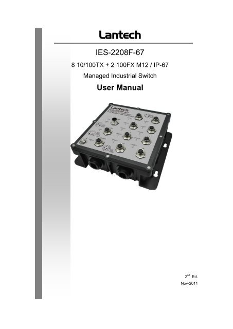
<strong>Lantech</strong><strong>IES</strong>-<strong>2208F</strong>-<strong>67</strong>8 10/100TX + 2 100FX M12 / IP-<strong>67</strong>Managed Industrial SwitchUser Manual2 nd Ed.Nov-2011
ContentOverview ............................................................ 1Introduction .............................................................. 1Features – <strong>IES</strong>-<strong>2208F</strong>-<strong>67</strong> ......................................... 3Technical Specifications – <strong>IES</strong>-<strong>2208F</strong>-<strong>67</strong> ................ 4Packing List .............................................................. 6Safety Precaution ..................................................... 6Hardware Description ......................................... 7Physical Dimensions ................................................ 7<strong>IES</strong>-<strong>2208F</strong>-<strong>67</strong> .................................................................... 7Bottom View ............................................................. 8LED Indicators .......................................................... 9<strong>IES</strong>-<strong>2208F</strong>-<strong>67</strong> .................................................................... 9Installation ........................................................ 10Fast Ethernet Ports ................................................ 10Wiring the Power Inputs ......................................... 11Wiring the P-Fail Alarm Contacts ........................... 12Wall Mounting ........................................................ 13
Grounding the Ethernet Switch .............................. 14Installation Steps .................................................... 15Configuration .................................................... 16RS-232 Console ..................................................... 16Pin Assignments ............................................................. 16Login in the Console Interface ......................................... 17SSH ........................................................................ 19Configuring PuTTY .......................................................... 19Web-Based Management ...................................... 24SSL ................................................................................. 25System Information ......................................................... 27IP Configuration .............................................................. 28DHCP Server .................................................................. 31TFTP ............................................................................... 35System Event Log ........................................................... 38Fault Relay Alarm ............................................................ 44SNTP Configuration ........................................................ 45IP Security ....................................................................... 49User Authentication ......................................................... 51N-Key Transaction .......................................................... 52Port Statistics .................................................................. 53
Port Control ..................................................................... 55Port Trunk ....................................................................... 57Port Mirroring .................................................................. 65Rate Limiting ................................................................... 66VLAN Configuration ........................................................ <strong>67</strong>Rapid Spanning Tree ...................................................... 76SNMP Configuration ....................................................... 80QoS Configuration ........................................................... 86X-Ring2 ........................................................................... 89LLDP Configuration ......................................................... 92802.1X/Radius................................................................. 93MAC Address Table ........................................................ 97IGMP/MLD Snooping .................................................... 101Static Filtering ............................................................... 102Factory Default .............................................................. 103Save Configuration ........................................................ 104System Reboot.............................................................. 105Troubleshooting ............................................. 106Appendix A—Command Sets ........................ 107Command Level ................................................... 107System Commands Set ................................................. 108
Port Commands Set ...................................................... 111Trunk Commands Set ................................................... 114VLAN Commands Set ................................................... 115Spanning Tree Commands Set ..................................... 117QOS Commands Set .................................................... 120IGMP Commands Set ................................................... 121MLD Commands Set ..................................................... 121Multicast Static Filtering Table Commands Set ............. 122MAC / Filter Table Commands Set ................................ 123SNMP Commands Set .................................................. 124Port Mirroring Commands Set ....................................... 126802.1x Commands Set .................................................. 127TFTP Commands Set.................................................... 129SystemLog, SMTP and Event Commands Set .............. 129SNTP Commands Set ................................................... 131X-ring2 Commands Set ................................................. 133Fault Relay Alarm Commands Set ................................ 133N-Key Commands Set................................................... 134LLDP Commands Set.................................................... 134IPv6 Commands Set ..................................................... 134
OverviewIntroductionTo create the reliability in your network, the IP-<strong>67</strong> Managed IndustrialSwitch comes equipped with a proprietary redundant networkprotocol—X-Ring II, which provides users with an easy way to establisha redundant Ethernet network with ultra high-speed recovery time lessthan 10ms. Also, the long MTBF (Mean Time Between Failures)ensures that the industrial switch will continue to operate until a Gigabitnetwork infrastructure has been established without requiring any extraupgrade costs.Apart from eight fast Ethernet ports, the <strong>IES</strong>-<strong>2208F</strong>-<strong>67</strong> also comesequipped with 2 waterproof fiber ports for both single and mult modefiber optic cabling. The fiber slots can be used for the application ofwideband uploading and long distance transmission to fit the fieldrequest flexibility.Heavy DutyDesigned with circular M12 connectors for Fast Ethernet interface, theManaged Industrial Switch provides the rugged construction whichcomplies with IP<strong>67</strong> standards. Therefore, the equipment is especiallyintended for the damp, dusty, and vibrant environments.Dual Power InputsThe redundant power input design for the IP-<strong>67</strong> Managed IndustrialSwitch gives a backup power solution. With both the power inputssupplied, and if either one fails the other one will be activated to keepthe system operating continually. When one of the power inputs fails,the P-Fail LED indicator lights up and send an alarm through the relayoutput for notification purposes.1
Flexible MountingThe IP-<strong>67</strong> Managed Industrial Switch is compact and can be mountedon the wall, so it is suitable for any space-constrained environment.Wide Operating TemperatureThe operating temperature of the IP-<strong>67</strong> Managed Industrial Switch isbetween -40 and 75 o C. With such a wide range, you can use the IP-<strong>67</strong>Managed Industrial Switch in some of the harshest industrialenvironments that exist.Easy TroubleshootingLED indicators make troubleshooting quick and easy. Each10/100Base-TX port has an LED indicator displaying the link status.Also the indicators PWR1, PWR2 and P-Fail help you diagnose thesystem immediately.2
Features – <strong>IES</strong>-<strong>2208F</strong>-<strong>67</strong>• 2Gbps back-plane (switching fabric)• 2 x 100Base-FX waterproof LC-type single/multi mode fiber ports• X-Ring II path redundant supported• IPv6 supported• Wide-range redundant power• TFTP firmware update and system configuration restoration/backup• Supports N-Key for configuration restoration/backup (optional)3
Technical Specifications – <strong>IES</strong>-<strong>2208F</strong>-<strong>67</strong>The technical specifications of <strong>IES</strong>-<strong>2208F</strong>-<strong>67</strong> are listed as follows.<strong>Communications</strong>StandardLANTransmission SpeedIEEE 802.3, 802.3u, 802.3x, 802.3adIEEE 802.1d, 802.1p, 802.1Q, 802.1w, 802.1x10/100BaseTX, 100BaseFXUp to 100 MbpsInterfaceEthernet8 x M12, 4-pole D-coded, female (10/100TX)2 x 100 LC type socket with waterproof (100FX)Console1 x M12, 8-pole A-coded, female (RS-232)Power Receptacle 1 x M12, 5-pole A-coded, maleRelay Alarm 1 x M12, 3-pole A-coded, female (1A @ 24 V DC )LED IndicatorsSystem: Power1, Power2, P-Fail, R-Master10/100BaseTX port: Link/Active100BaseFX port: Link/ActiveManagementConfigurationSNMP MIBVLANRedundancySecurityWeb browser, serial console, SNMP v1/v2c/v3,Telnet, TFTP, N-Key (optional), IPv6, SNTPRFC 1215 Trap, RFC1213 MIBII, RFC 1157 SNMPMIB, RFC 1493 Bridge MIB, RFC 2<strong>67</strong>4 VLAN MIB,RFC1643 , RFC 1757, RSTP MIB, LLDP MIB,Private MIBPort-based VLAN, IEEE 802.1Q tagged anddouble-tagged VLAN, GVRP802.1w/d RSTP/STPX-Ring II (Recovery time < 10ms)SSL, SSH, DHCP Server with Port-IP binding,IP access security, user authentication, multi-user4
Traffic ControlDiagnosticslogin , 802.1X port access controlPort trunking with LACP, rate limit and storm control,IGMP Snooping/Query for multicast group, multicastfiltering, IEEE 802.3x flow control, IEEE 802.1p QoSPort mirroring, real-time traffic statistics, MACaddress table, system event log, E-mail alert,SNMP trap, RMON, LLDP/LLDP-MEDPowerPower ConsumptionPower Input8.1 watts max. @ 48 V DC2 x unregulated +12 ~ 48 V DCMechanismDimensions (WxHxD)EnclosureInstallation193 x 176 x 62.5 mmIP-<strong>67</strong> protection, aluminum shellWall-mountEnvironmentOperating TemperatureOperating HumidityStorage TemperatureStorage Humidity-40 ~ 75 o C5% ~ 95% (non-condensing)-40 ~ 85 o C5% ~ 95% (non-condensing)CertificationsSafety UL 508RailwayEN50155 compliantEMCCE, FCC Class ACE EN61000-6-2CE EN61000-6-4CE EN61000-4-2 (ESD)CE EN61000-4-3 (RS)CE EN61000-4-4 (EFT)CE EN61000-4-5 (Surge)5
Free FallShockVibrationPacking ListCE EN61000-4-6 (CS)CE EN61000-4-8 (Magnetic Field)IEC60068-2-32IEC61373IEC61373• 1 x IP-<strong>67</strong> Managed Industrial Switch• 1 x M12 to D-sub 9 female console cable• 1 x User Manual (CD-ROM)Compare the contents of the industrial switch with the standard checklistabove. If any item is damaged or missing, please contact the local dealerfor service.Safety PrecautionAttention If DC voltage is supplied by an external circuit, please use aprotection device on the power supply input.6
Hardware DescriptionThis section is intended to introduce the industrial switch‘s hardware specification, port,cabling and wiring information.Physical Dimensions<strong>IES</strong>-<strong>2208F</strong>-<strong>67</strong>The figure below illustrates the dimensions 193mm x 176mm x 62.5mm (W x H x D) forthe <strong>IES</strong>-<strong>2208F</strong>-<strong>67</strong>.Mechanical Dimensions7
Bottom ViewThe <strong>IES</strong>-<strong>2208F</strong>-<strong>67</strong>, as the figure shown below, is equipped with two LC type fiberconnectors located on the bottom.The bottom side of the <strong>IES</strong>-<strong>2208F</strong>-<strong>67</strong>8
LED Indicators<strong>IES</strong>-<strong>2208F</strong>-<strong>67</strong>LED indicators located on the front panel display the power status and network statusof the <strong>IES</strong>-<strong>2208F</strong>-<strong>67</strong>. Please refer to the following table for further details.LED Color DescriptionPWR1GreenOnOffPower input 1 is activePower input 1 is inactivePWR2GreenOnOffPower input 2 is activePower input 2 is inactiveP-Fail(depends on theFault Relay Alarmconfiguration)RedOnOffPower or Ethernet port failure occursNo failure occursR-MasterGreenOnOffThe industrial switch is the master of the X-ring groupNon-master deviceOnLC fiber port is linkingP9, P10 GreenBlinksOffOnData is transmitting or receivingNot connected to networkConnected to networkP1 ~ P8GreenBlinksData is transmitting or receivingOffNot connected to networkDefinition of LED indicators9
InstallationFast Ethernet PortsThe M-12 D-coded Fast Ethernet ports are auto-sensing for 10Base-T or 100Base-TXdevices connections. Auto MDI/MDIX means that you can connect to another switch orworkstation without changing straight through or crossover cabling.• M12 D-coded Connector Pin AssignmentsPin NumberAssignments1 Tx+2 RX+3 TX-4 Rx-Note“+” and “-” signs represent the polarity of the wires that make up each wirepair.10
Wiring the Power InputsConnect the positive and negative wires to PWR1 (V1+, V1-) and PWR2 (V2+, V2-) asthe power pin assignments shown below.Power1 & Power2 Contacts of the M12 Connector11
Wiring the P-Fail Alarm ContactsThe ―P-Fail‖ alarm relay is provided to signal critical error conditions that may occur onthe switch. The contacts are energized upon powering up of the switch and remainenergized until a critical error occurs including power failure, Ethernet port disconnectionand MAC violation. Take the wiring illustration below as an example that illustrates theproper relay connection forming a normally close circuit, and the connection is to bebroken when an error occurs.P-Fail Alarm Wiring12
Wall MountingBesides desktop installation, the industrial switch is specially designed to hang on thewall for space-constrained environments. The drawing below illustrates the wall-mountinginstallation to hang the switch on the wall via the four mounting holes on the sides.Hang the switchon the wallGrounding screw holesGrounding Lug13
Grounding the Ethernet SwitchAs the figure illustrated above, you can use an M3 screw to secure a grounding wire tothe side screw holes near the ground mark or to the grounding lug at the corner of thefront panel.NoteTo earth the switch to ground with the grounding lug, pleaseprepare an M8 wrench to hold the grounding contact fromrotating when you are trying to tighten or release the fixingscrew above the contact.14
Installation Steps1. Unpack the Industrial switch2. To hang the Industrial switch on the wall, please refer to the Wall Mounting section.3. Use an M8 wrench to hold the grounding contact and remove the fixing screw abovethe contact.4. Align the grounding lug with the contact; and still use the M8 wrench to hold thecontact from rotating while you are tightening the fixing screw.5. To power on the Industrial switch, please refer to the Wiring the Power Inputssection for further information on how to wire the power. And then the power LED onthe Industrial switch will light up. Please refer to the LED Indicators section forindication of LED lights.6. Prepare the M12 D-Code Fast Ethernet Port mating cable for Ethernet connection.7. The Fast Ethernet port LED on the Industrial switch will light up when the cable isconnected with the network device. Please refer to the LED Indicators section forLED light indication.8. When all connections are set and LED lights all show in normal, the installation iscomplete.Note This equipment is intended for use in a Pollution Degree 2industrial environment.15
ConfigurationRS-232 ConsoleOne end of the supplied console cable is D-sub 9 female connector and the other end isM12, 8-pole A-coded male connector. Attach the D-sub end to a PC or terminal and the ofM12 end to the console port of the switch. The connected terminal or PC must supportthe terminal emulation program.Pin AssignmentsDB9D-sub 9M12M12ConnectorConnectorConnectorConnectorPin Assignments(To PC)(To Switch)Pin AssignmentsPin 2Pin 2TXTXPin 3Pin 3RXRXPin 5Pin 5GNDGND16
Login in the Console InterfaceAfter the connection between Switch and PC is ready, turn on the PC and run a terminalemulation program like Hyper Terminal and configure its communication parametersto match the following default characteristics of the console port:Baud Rate: 9600 bpsData Bits: 8Parity: noneStop Bit: 1Flow control: NoneThe settings of communication parameters17
Having finished the parameter settings, click ‗OK‘. When the blank screen shows up,press Enter to have the login prompt appear. Key in ‗root‘ (default value) for both UserName and Password (press Enter to switch between); and then press Enter to have theMain Menu of console management show up. Please see the figure below.Console login interfaceThe system supports the console management—CLI command. After you log in on to thesystem, you will see a command prompt. To enter CLI management interface, type in―enable‖ command.CLI command interfaceFor further details about the CLI commands, please refer to Appendix A CommandSets.18
SSHThe Ethernet switch also supports SSH (Secure SHell) which allows the user to log infrom a remote computer over the network.The next section is intended to guide users on how to use an SSH client—PuTTY tomake a connection to the Ethernet switch.Configuring PuTTYLaunch PuTTy, and you will see a dialog box which allows you to control everythingPuTTY can do. You don‘t usually need to change most of the configuration options. Tostart the simplest kind of session, please follow the steps below.1. In the ‗Host Name (or IP address)‘ field, enter the Internet host name or IP address ofthe server you want to connect to.2. Now select a login session protocol to use, from the ‗Connection type‘ radio buttons.For a login session, you should always select SSH.Basic Options for PuTTY19
3. Click the Connection SSH node of the tree-menu to configure options forcontrolling SSH connections.4. Tick the check box labeled ‗Don’t start a shell or command at all‘.Options Controlling SSH Connections5. Click the Connection SSHTunnel node of the tree-menu to configure options forcontrolling SSH port forwarding.6. Tick the check box labeled ‗Local ports accept connection from other hosts‘ thatallows you to set up local-to-remote port forwardings (including dynamic portforwardings) in such a way that machines other than your client PC can connect to theforwarded port.7. Add a new forwarded port to connect to the SSH server and set the type to ‗‘Local.Options Controlling SSH Port Forwarding20
8. After filling in, click the Add button. And you will see an entry added to the list box.Entry of Port Forwarding Added9. You can also save your preferred PuTTY options for quick connection the next time.Just go back to the Session node, and click the Save button with a session name filled.When you see the saved session in the list box, the session is saved.Saving Sessions21
10. To connect to the SSH server, select the session name and click the Open button.And then you will see a window shows up with prompt message ‗login as:‘. Type‗guest‘ for both user name and password.Logging-in interface11. Run the ‗cmd‘ command to start the command prompt interface. Type ‗telnetlocalhost 23‘ and press Enter.Command Prompt interface22
12. When finished, a telnet session is successfully made using the SSH protocol.Console via SSH23
Web-Based ManagementThis industrial switch provides a convenient configuring way via web browser. You canfollow the steps below to access the equipment.NoteYour host PC should be in the same VLAN setting with the industrialswitch, or the management will not be configured.Connect the industrial switch to the Ethernet then your host PC could be configured viaEthernet. Or you can directly connect it to your host PC with a straight-through or crossover Ethernet cable.Before to use web management, install the industrial switch on the network and makesure that any one of the PCs on the network can connect with the industrial switchthrough the web browser. The industrial switch default value of IP, subnet mask,username and password are as below.• IP Address: 192.168.16.1• Subnet Mask: 255.255.255.0• Default Gateway: 192.168.16.254• User Name: root• Password: root1. Launch the Internet Explorer on the PC.2. Type the IP address of the switch in the URL field, and then Press ―Enter‖.3. With the login dialog box showing up, type the user name and password in therespective fields. The default user name and password are the same as ‗root‘.4. Press Enter or click the OK button, and then the home screen of the Web-basedmanagement appears. You can change user name/password in the UserAuthentication section.24
Login dialog boxSSLThe Ethernet switch also provides an option for you to connect with your browser viaHTTP over SSL, called HTTPS. The SSL (Secure Socket Layer) protocol allows users tomake a secured session between the browser (client) and the Ethernet switch (server).You can then type the prefix ―https://― followed by the IP address of the Ethernet switch inthe URL of the browser. Beside the URL a padlock icon shows up indicating that client issuccessfully connecting to server via HTTPS.25
In the main page, you can find the tree menu structure of the Ethernet switch in the leftside. Click the ―+‖ symbol to unroll the hiding hyperlink, and click any one of thehyperlinks to open its function page.26
System InformationHere you can view the system information and assign the system name and location tomake this switch more easily identified on your network.• System Name: Assign the name of the switch. The maximum length is 64 bytes.• System Description: A read-only field displaying the description of the switch.• System Location: Assign the switch physical location. The maximum length is 64bytes.• System Contact: Enter the name of contact person or department.• Firmware Version: Displays the switch‘s firmware version.• Kernel Version: Displays the kernel software version.• MAC Address: Displays the unique hardware address assigned by manufacturer(default).• Click Apply to have the configuration take effect.[NOTE]Don‘t set ―0‖ for the first segment of the subnet mask and default gateway(000.xxx.xxx.xxx).Refresh the web screen if the web could not be displayed while you changethe setting.System Information interface27
IP ConfigurationDue to the foreseeable address exhausition of IPv4, the IP configuration of the Ethernetswitch is designed to provide an interface for users to configure the switch running bothIPv4 and IPv6 architecture.IPv4The IPv4 tab allows users to configure the switch to receive an IP address from DHCPserver or manually fill in IP Address, Subnet Mask, Gateway, IP addresses of theprimary and the secondary DNS servers.• DHCP Client: Enable or disable the DHCP client function. When the DHCP Clientfunction is enabled, the industrial switch will be assigned an IP address from thenetwork DHCP server. The default IP address will be replaced by the assigned IPaddress on DHCP server. After users click Apply, a popup dialog shows up. It is toinform the user that when the DHCP client is enabled, the current IP will lose and theuser should find the new IP on the DHCP server• IP Address: Assign the IP address for the indistrial switch. With the DHCP Clientfunction enabled, the switch is configured as a DHCP client and users doesn‘t needto assign the IP address that is assigned by the DHCP server. The default IP is192.168.16.1 or the user has to assign an IP address manually when DHCP Client isdisabled.• Subnet Mask: Assign the subnet mask to the IP address. If the DHCP Clientfunction is disabled, the user has to assign the subnet mask manually.• Gateway: Assign the network gateway for the switch. If the DHCP Client function isdisabled, the user has to assign the gateway manually. The default gateway is192.168.16.254.• DNS1: The abbreviation of Domain Name Server—an Internet service that translatesdomain names into IP addresses. The domain name is in alphabetic order, which iseasy to be remembered. The Internet is based on IP address. Therefore, every timeyou use a domain name, a DNS service must translate the name into thecorresponding IP address. For example, the domain name www.net.com mighttranslate to 192.168.16.1.28
• DNS2: The backup for DNS1. When DNS1 cannot function, DNS2 will then replaceDNS1.• When finished, click Apply to have the configuration take effect.IP configuration—IPv429
IPv6The IPv6 tab mainly features two fields displaying the Ethernet switch‘s <strong>Global</strong> UnicastAddress and Link-Local Address.<strong>Global</strong> Unicast Address: A display-only field. When this Ethernet switch is connected toa network segment where one or more routers connected, the Ethernet switch will beassigned an address known as <strong>Global</strong> Unicast Address by the router(s). Being assignedthe <strong>Global</strong> Unicast Address, the Ethernet switch can then have access to differentnetwork segments.Link-Local Address: A display-only field. Link-Local Address is for use duringauto-configuration and when no any router presents. Being assigned the Link-LocalAddress, the Ethernet switch can have access to all hosts on the same local segment towhere it belongs.IP configuration—IPv630
DHCP ServerDHCP is the abbreviation of Dynamic Host Configuration Protocol that is a protocol forassigning dynamic IP addresses to devices on a network. With dynamic addressing, adevice can have a different IP address every time it connects to the network. In somesystems, the device's IP address can even change while it is still connected. DHCPalso supports a mix of static and dynamic IP addresses. Dynamic addressing simplifiesnetwork administration because the software keeps track of IP addresses rather thanrequires an administrator to manage the task. This means that a new computer can beeasily added to a network without the hassle of manually assigning it a unique IPaddress.The system provides the DHCP server function. With the DHCP server functionenabled, the switch system is able to be configured as a DHCP server.31
System Configuration• DHCP Server: This pull-down menu allows you to configure the switch to be theDHCP server on your local network.• Low IP Address: Type in an IP address as the beginning of a range of thedynamic IP address. As the figure shown below, for example, 192.168.16.100 isthe relatively low IP address of the range.• High IP Address: Type in an IP address as the beginning of a range of thedynamic IP address. As the figure shown below, for example, 192.168.16.200 isthe relatively high IP address of the range.• Subnet Mask: Type in the subnet mask of the IP configuration.• Gateway: Type in the IP address of the gateway in your network.• DNS: Type in the IP address of Domain Name Server in your network.• Lease Time (sec): The length of time the dynamic IP addresses assigned toclients.• Click Apply to have the configuration take effect.DHCP Server—System Configuration interface32
Client EntriesWhen the DHCP Server function is enabled, the system will collect the DHCP clientinformation including the assigned IP address, the MAC address of the client device,the IP assigning type, states and lease time.DHCP Client Entries interface33
Port and IP BindingsAs the figure shown below, the switch will assign the IP address to the connected clientaccording to the Port-IP binding table. The user is allowed to fill each port with oneparticular IP address. When the device is connecting to the port and asks for IP assigning,the system will assign the IP address bound with the port to the device.Port and IP Bindings interface34
TFTPIt provides the functions allowing the user to update the switch firmware via the TrivialFile Transfer Protocol (TFTP) server. Before updating, make sure the TFTP server isready and the firmware image is located on the TFTP server.Update Firmware• TFTP Server IP Address: Type in the IP address of the TFTP server.• Firmware File Name: Type in the name of the firmware image file to be updated.• When finished, click Apply to start updating.Update Firmware interface35
Restore ConfigurationYou can restore a previous backup configuration from the TFTP server to recover thesettings. Before doing that, you must locate the image file on the TFTP server first forthe switch to download back the flash image.• TFTP Server IP Address: Type in the IP address of the TFTP server.• Restore File Name: Type in the correct file name for restoring.• When finished, click Apply to start configuration restoration.Restore Configuration interface36
Backup ConfigurationYou can back up the current configuration from flash ROM to the TFTP server for thepurpose of recovering the configuration later. It helps you avoid wasting time onconfiguring the settings by backing up the entire configuration.• TFTP Server IP Address: Type in the IP address of the TFTP server.• Backup File Name: Type in the file name.• When finished, click Apply to start backing up.Backup Configuration interface37
System Event LogThis page allows the user to decide whether to send the system event log, and select themode which the system event log will be sent to client only, server only, or both client andserver. What kind of event log will be issued to the client/server depends on the selectionon the Event Configuration tab.System Event Log—Syslog Configuration• Syslog Client Mode: Select the system log mode—Client Only, Server Only, orBoth. ‗Client Only‘ means the system event log will only be sent to this interface of theswitch, but on the other hand ‗Server Only‘ means the system log will only be sent tothe remote system log server with its IP assigned. If the mode is set in ‗Both‘, thesystem event log will be sent to the remote server and this interface.• Syslog Server IP Address: When the ‗Syslog Mode‘ item is set as Server Only/Both,the user is required to assign the system log server IP address to which the log will besent.• Click Reload to refresh the event log displaying area.• Click Clear to clear the displaying area.• Make sure the selected mode and IP address, if needed, is correct and click Apply tohave the setting take effect.38
Syslog Configuration interface39
System Event Log—SMTP ConfigurationSimple Mail Transfer Protocol (SMTP) is the standard for email transmissions acrossthe network. You can configure the SMTP server IP address, sender mail account,password, and the recipient email account to which the e-mail alert will send. Besides,this page provides the authentication mechanism including authentication stepsthrough which the client effectively logs in to the SMTP server during the process ofsending e-mail alert.• Email Alert: With this function enabled, the user is allowed to configure the detailsettings for sending the e-mail alert to the SMTP server when the events occur.• SMTP Server IP Address: Assign the mail server IP address (when Email Alertis enabled, this field will then be available).• Sender: Type in an alias of the switch in complete email address format, e.g.switch101@123.com, to identify where the e-mail alert comes from.• Authentication: Tick the checkbox to have the mail account, password andconfirm password fields show up. Configure the email account and password forauthentication procedures when this switch logs in to the SMTP server.• Mail Account: Set up the email account, e.g. johnadmin, to receive the email alert.It must be an existing email account on the mail server.• Password: Type in the password to the email account.• Confirm Password: Reconfirm the password.• Rcpt e-mail Address 1 ~ 6: You can also specify up to 6 e-mail accounts toreceive the email alert.• Click Apply to have the configuration take effect.40
SMTP Configuration interface41
System Event Log—Event ConfigurationThe checkboxes and pull-down menus are not available unless the Syslog Client Modeon the Syslog Configuration tab and the E-mail Alert on the SMTP Configuration tab areenabled first.This tab mainly controls whether an event notification is to be sent to the Syslog/SMTPserver. The part of System Event Selection controls the event notification includingDevice Cold Start, Authentication Failure, and MAC Violation. With the Syslog/SMTPcheckbox ticked, the event log/email alert will be sent to the system log server/SMTPserver respectively. As for the part of Port Event Selection, port events (link up, linkdown, and both) can be sent to the system log server/SMTP server by setting the triggercondition for each port respectively.• System event selection: There are three event types—Device Cold Start,Authentication Failure, and MAC Violation.‣ Device Cold Start: Tick the Syslog/SMTP checkboxes respectively to have thesystem issue the event log/email alert to the system log/SMTP server when thedevice executes the cold start action.‣ Authentication Failure: When the SNMP authentication fails, the system willissue the event log/email alert to the system log/SMTP server respectively.‣ MAC Violation: If a device whose MAC address is not in the MAC address tableattempts to access the port, the system will issue the event log/email alert to thesystem log/SMTP server respectively. (Note that the Security property of thePort Control function also has to be set at ‗On‘. See the Port Control sectionfor further details.)• Port event selection: Each drop-down menu has four options—Disable, Link UP,Link Down, and Link UP & Link Down. Disable means no event will be sent to thesystem log/SMTP server.‣ Link UP: The system will issue a log message only when the link-up event ofthe port occurs.‣ Link Down: The system will issue a log message only when the link-down eventof port occurs.42
‣ Link UP & Link Down: The system will issue a log message at the time whenport connection is link-up and link-down.Event Configuration interface43
Fault Relay AlarmThe Fault Relay Alarm function provides the Power Failure, Port Link Down/Broken andMAC Violation detection. Tick the checkbox to enable the relay alarming function. Pleaserefer to the segment of ‗Wiring the Fault Alarm Contacts‘ for the external warningdevice installation.• Power Failure: With the checkbox ticked the relay device inside the industrial switchchanges its state and the FAULT LED indicator is on if a power failure occurs.• Port Link Down/Broken: With the checkbox ticked the relay device inside theindustrial switch changes its state and the FAULT LED indicator is on if thecorresponding port‘s states become link down or broken.• MAC Violation: With the checkbox ticked the relay device inside the industrialswitch changes its state and the FAULT LED indicator is on if a MAC violation eventoccurs.Fault Relay Alarm interface44
SNTP ConfigurationSNTP (Simple Network Time Protocol) is a simplified version of NTP which is an Internetprotocol used to synchronize the clocks of computers with some time reference. Becausetime usually just advances, the time on different node stations might be different. With thecommunicating programs running on those devices, it would cause time to jump forwardand back, a non-desirable effect. Therefore, the switch provides comprehensivemechanisms to access national time and frequency dissemination services, organize thetime-synchronization subnet and the local clock in each participating subnet peer.Daylight Saving Time (DST) is the convention of advancing clocks so that afternoonshave more daylight and mornings have less. Typically clocks are adjusted forward onehour near the start of spring and are adjusted backward in autumn.• SNTP Client: Enable/disable the SNTP function to get the time from the SNTPserver.• Daylight Saving Time: This function is used to enable/disable Daylight SavingPeriod and Daylight Saving Offset fields.• UTC Timezone: Set the location time zone for the switch. The following table listsdifferent location time zones for your reference.Local Time Zone Conversion from UTC Time at 12:00 UTCNovember Time Zone - 1 hour 11 amOscar Time Zone -2 hours 10 amADT - Atlantic Daylight -3 hours 9 amAST - Atlantic StandardEDT - Eastern DaylightEST - Eastern StandardCDT - Central DaylightCST - Central StandardMDT - Mountain Daylight-4 hours 8 am-5 hours 7 am-6 hours 6 am45
MST - MountainStandardPDT - Pacific DaylightPST - Pacific StandardADT - Alaskan Daylight-7 hours 5 am-8 hours 4 amALA - Alaskan Standard -9 hours 3 amHAW - HawaiianStandard-10 hours 2 amNome, Alaska -11 hours 1 amCET - Central EuropeanFWT - French WinterMET - Middle EuropeanMEWT - MiddleEuropean WinterSWT - Swedish WinterEET - Eastern European,USSR Zone 1BT - Baghdad, USSRZone 2+1 hour 1 pm+2 hours 2 pm+3 hours 3 pmZP4 - USSR Zone 3 +4 hours 4 pmZP5 - USSR Zone 4 +5 hours 5 pmZP6 - USSR Zone 5 +6 hours 6 pmWAST - West AustralianStandardCCT - China Coast,USSR Zone 7JST - Japan Standard,USSR Zone 8+7 hours 7 pm+8 hours 8 pm+9 hours 9 pm46
EAST - East AustralianStandard GSTGuam Standard, USSRZone 9IDLE - International DateLineNZST - New ZealandStandardNZT - New Zealand+10 hours 10 pm+12 hours Midnight• SNTP Sever URL: Specify the SNTP server IP address. You can assign a localnetwork time server IP address or an internet time server IP address.• Switch Timer: When the switch has successfully connected to the SNTP serverwhose IP address was assigned in the field of SNTP Server URL, the currentcoordinated time is displayed here.• Daylight Saving Period: Set up the start and end date/time of the daylight savingperiod. Please key in the value in the format of ‗YYYYMMDD‘ and ‗HH:MM‘ (leave aspace between ‗YYYYMMDD‘ and ‗HH:MM‘).‣ YYYYMMDD: an eight-digit year/month/day specification.‣ HH:MM: a five-digit (including a colon mark) hour/minute specification.For example, key in ‗20070701 02:00‘ and ‗20071104 02:00‘ in the two fieldsrespectively to represent that DST begins at 2:00 a.m. on March 11, 2007 and endsat 2:00 a.m. on November 4, 2007.• Daylight Saving Offset (mins): For non-US and European countries, specify theamount of time for day light savings. Please key in the valid figure in the range ofminute between 0 and 720, which means you can set the offset up to 12 hours.• Synchronization Interval (secs): The Synchronization Interval is used for sendingsynchronizing packets periodically. Users can assign the time ranging from 64 to1024 seconds. The ―0‖ value displaying by default means that you disable theauto-synchronized feature in the SNTP client mode. You can enable the feature byfilling the interval range from 64~1024 seconds.• Click Apply to have the configuration take effect.47
SNTP Configuration interface48
IP SecurityIP security function allows the user to assign up to 10 specific IP addresses that havepermission to manage the switch through the http and telnet services for securing switchmanagement. The purpose of giving permission to limited IP addresses is to allow onlythe authorized personnel/device to do the management task on the switch.• IP Security Mode: With this selection item set in the Enable mode, the EnableHTTP Server, Enable Telnet Server checkboxes and the ten security IP fields willthen be available. If not, those items will appear in grey.• Enable HTTP Server: With this checkbox ticked, Ethernet devices whose IPaddresses match any one of the ten IP addresses in the Security IP table will begiven permission to access this switch via the HTTP service.• Enable Telnet Server: With this checkbox ticked, Ethernet devices whose IPaddresses match any one of the ten IP addresses in the Security IP table will begiven permission to access this switch via the telnet service.• Security IP 1 ~ 10: The system allows the user to assign up to 10 specific IPaddresses for access security. Only when IP Security Mode is enabled can these10 IP addresses access and manage the switch through the HTTP/Telnet services.• And then, click Apply to have the configuration take effect.[NOTE]Remember to execute the ―Save Configuration‖ action, otherwise the newconfiguration will lose when the switch powers off.49
IP Security interface50
User AuthenticationThe User Authentication interface allows users to configure different login accounts forsecurity reasons. The Admin User account is given administrative privileges. If you wantothers to access the Ethernet switch with a restricted account, configure the Guest Useraccount for login authentication.Admin User• User Name: The admin user account is root by default. Type in the User Name fieldwith a new name as you wish.• New Password: The password to the admin user account is root by default. Type inthe New Password field with a new password as you wish.• Confirm password: Type in the new password again for confirmation.• When finished, click Apply to have the configuration take effect.Guest User• User Name: The guest user account is user by default. Type in the User Name fieldwith a new name as you wish.• New Password: The password to the guest user account is user by default. Type inthe New Password field with a new password as you wish.• Confirm password: Type in the new password again for confirmation.• When finished, click Apply to have the configuration take effect.User Authentication interface51
N-Key TransactionUsers can back up or restore configuration from/to the switch via this interface.• Auto mode: Tick this check box and click Apply to enable the function that with theN-Key device connected to the RS-232 console port, the switch will automaticallyload the system configuration from N-Key when booting up.• Backup: Make sure N-Key is connected with the RS-232 console port and then clickthis button to back up the current configuration from switch.• Restore: Make sure N-Key is connected and then click this button to load the systemconfiguration from N-Key.Note: After clicking the Backup/Restore button, for the purpose of confirmation, a dialogbox shows up to display the current N-Key information including model name, firmwareversion, kernel version, and the last backup time.N-Key Transaction interface52
Port StatisticsThe following chart provides the current statistics information which displays the real-timepacket transfer states for each port. The user might use the information to plan andimplement the network, or check and find the problem when the collision or heavy trafficoccurs.• Port: Port number indexed.• Type: Displays the network media type of the port.• Link: The states of linking—‗Up‘ or ‗Down‘.• State: Displays port states set by the Port Control interface. When the state isdisabled, the port will not transmit or receive any packet.• Tx Good Packet: The counts of transmitting good packets via this port.• Tx Bad Packet: The counts of transmitting bad packets (including undersize [lessthan 64 bytes], oversize, CRC Align errors, fragments and jabbers packets) via thisport.• Rx Good Packet: The counts of receiving good packets via this port.• Rx Bad Packet: The counts of receiving good packets (including undersize [lessthan 64 bytes], oversize, CRC error, fragments and jabbers) via this port.• Tx Abort Packet: The counts of aborted packets while transmitting.• Packet Collision: The counts of packet collision.• Packet Dropped: The counts of dropped packets.• Rx Bcast Packet: The counts of broadcast packets.• Rx Mcast Packet: The counts of multicast packets.• Click the Clear button to clean all counts.53
Port Statistics interface54
Port ControlIn Port Control you can configure the parameters of the connection for each port.• Port: Scroll up/down the scroll bar and click on the port number to choose aparticular port to be configured.• State: Enable/disable the port. If the port state is set on ‗Disable‘, the port will not beable to receive or transmit any packet.• Negotiation: Options include Auto and Force. With this parameter set on Auto, thespeed and duplex fields display in grey, which means the port are negotiatedautomatically. When you set it on Force, you have to set the speed and duplex modemanually by clicking the pull-down menus of the Speed and Duplex fields.• Speed: It is available for selecting when the Negotiation field is set on Force. Whenthe Negotiation field is set on Auto, this field becomes a read-only field displaying ingrey.• Duplex: It is available for selecting when the Negotiation field is set on Force. Whenthe Negotiation field is set on Auto, this field becomes a read-only field displaying ingrey.• Flow Control: Whether the receiving node sends feedback to the sending node isdetermined by this item. With this item enabled, if the input data rate of the receivingdevice exceeds, the receiving device will send a PAUSE frame which halts thetransmission of the sender for a specified period of time. With this item disabled, thereceiving device will drop the packets it is unable to process.• Security: When the Security selection is set as ‗On‘, any access from the devicewhich connects to this port will be blocked unless the MAC address of the device isincluded in the static MAC address table. Keep in mind that the Security item is setas On so that the MAC violation event log/email alert will then be issued. Furtherinformation please see the segments of MAC Address Table—Static MACAddresses and System Event Log—Event Configuration.• Click Apply to have the configuration take effect.55
Port Control interface56
Port TrunkPort trunking is the combination of several ports or network cables to expand theconnection speed beyond the limits of any one single port or network cable. LinkAggregation Control Protocol (LACP), which is a protocol running on layer 2, providesa standardized means in accordance with IEEE 802.3ad to bundle several physicalports together to form a single logical channel. All the ports within the logical channelor so-called logical aggregator work at the same connection speed and LACPoperation requires full-duplex mode.Aggregator SettingPlease read the instrutions below to make an LACP or non-LACP trunk group.• System Priority: A value which is used to identify the controlling switch of anLACP link system. The switch with the lower value has the higher system priorityand is selected as the controlling end, which controls port priorities, of the LACPlink system.• Group ID: There are four trunk groups to be selected. Assign the group ID to theparticular trunk group.• LACP: Click the pull-down menu to enable/disable LACP for the trunk group. WithLACP enabled, a port which joins an LACP trunk group has to make anagreement with its member ports first. Please notice that a trunk group, includingmember ports split between two switches, has to enable the LACP function of thetwo switches. When disabled, the trunk group is a static trunk group. Theadvantage of having the LACP disabled is that a port joins the trunk group withoutany handshaking with its member ports; but member ports won‘t know that theyshould be aggregated together to form a logic trunk group.• Work Ports: This field allows the user to type in the total number of active portsup to four. With a LACP trunk group employed, for example you assign four portsto be the members of a trunk group whose Work Ports field is set as two theexcessive ports will be standby/redundant ports and can be aggregated instead ofworking ports that fail. As for the static trunk group (non-LACP), the number ofwork ports must equal the total number of the group member ports.57
• The system allows a maximum of four ports to be aggregated in a trunk group.Having configured the parameters above, highlight the ports in the right list box tojoin the trunk group. Click the Add button and the ports highlighted in the right listbox will be shifted to the left list box. To remove unwanted ports, select the ports inthe left list box and click the Remove button.• When LACP enabled, you can configure LACP Active/Passive states for eachmember port on the State Activity tab.• When finished, click Apply to take the configuration take effect.• To remove a trunk group, select the Group ID by clicking the pull-down menulabeled as ‗Group ID‘ and click then click the Delete button.Port Trunk—Aggregator Setting interface (four ports are added to the left field with LACP enabled)58
Aggregator Information• LACP DisabledHaving configured the aggregator setting with LACP disabled, you can check the statictrunk group information on the Aggregator Information tab.Assigning 2 ports to a trunk group with LACP disabledStatic Trunking Group Information tab• Group Key: This is a read-only field that displays the trunk group ID.• Port Member: This is a read-only field that displays the members of the statictrunk group.59
• LACP EnabledHaving configured the aggregator setting with LACP enabled, you can check thetrunking group information between two switches on the Aggregator Information tab.• Configuration for Switch 11. Set System Priority of the trunk group. The field displays with ‗1‘ by default.2. Select a trunk group ID by clicking the pull-down menu.3. Enable LACP.4. <strong>Inc</strong>lude the member ports by highlighting the ports in the right list box and thenclick the Add button. Note the number in the Work Ports field changesautomatically depending on how many ports you have selected.Switch 1 configuration interface60
Aggregation Information of Switch 15. Click on the Aggregator Information tab to check the trunked group informationas the illustration shown above after the two switches configured.61
• Configuration for Switch 2Switch 2 configuration interface1. Set System Priority of the trunk group. The field displays with ‗1‘ by default.2. Select a trunk group ID by clicking the pull-down menu.3. Enable LACP.4. <strong>Inc</strong>lude the member ports by highlighting the ports in the right list box and thenclick the Add button. Note the number in the Work Ports field changesautomatically depending on how many ports you have selected.62
Aggregation Information of Switch 25. Click on the Aggregator Information tab to check the trunked group informationas the illustration shown above after the two switches configured.63
State ActivityHaving configured the LACP aggregator on the Aggregator Setting tab, you may wantto change the state activity for the members of the LACP trunk group. You can tick/untickthe checkbox beside the state label. If you remove the tick mark of the corresponding portand click the Apply button, the port state activity will change to Passive.• Active: The port automatically sends LACP protocol packets.• Passive: The port does not actively send LACP protocol packets. It responds only ifit receives LACP protocol packets from the opposite device.[NOTE]A link having two passive LACP nodes will not perform dynamic LACPtrunk because both ports are waiting for an LACP protocol packet from theopposite device.State Activity of Switch 1State Activity of Switch 264
Port MirroringPort Mirroring is a method for monitoring of network traffic on switched networks. Trafficthrough ports can be monitored by one specific port, which means traffic going in or outthe monitored (source) ports will be duplicated into the mirroring (destination) port.• Destination Port: Select one port to be the destination (mirroring) port formonitoring both RX and TX traffic coming from the source port. Or, select two portsfor monitoring RX traffic and TX traffic respectively. Users can forward the trafficcaptured by the mirroring port to the packet analyzer like Netxray for furtheranalyses.• Source Port: Tick the checkbox to monitor the corresponding port. All monitoredport traffic will be copied to the mirroring (destination) port. Users can select multiplesource ports by ticking the RX or TX checkboxes.• When finished, click the Apply button.Port Mirroring interface65
Rate LimitingYou can respectively configure the ingress limitation type and ingress/egress rate foreach port.• Ingress Limit Frame Type: Select the limit type for ingress frames. Four options areavailable as follows:• All• Broadcast/Multicast/Flooded Unicast• Broadcast/Multicast• Broadcast onlyThe egress rate will limit all types of frame.Rate Limiting interface• Click the Ingress/Egress pull-down menus to select the bandwidth limit.• When finished, click Apply to have the configuration take effect.66
VLAN ConfigurationA Virtual LAN (VLAN) is a logical network grouping that limits the broadcast domain,which allows you to isolate network traffic. Therefore only the members of the sameVLAN will receive traffic from the ones among the same VLAN. Basically, creating aVLAN on a switch is logically equivalent of reconnecting a group of network devices toanother Layer 2 switch; however, all the network devices are still plugged into thesame switch physically.This switch supports Port-based and 802.1Q (tagged-based) VLAN. Please read thefollowing instructions to configure the appropriate type of VLAN for your need.VLAN Configuration interface<strong>67</strong>
• Port-based VLANA port-based VLAN normally consists of its members—ports, which means the VLANis created by grouping the selected ports. This method provides the convenience forusers to configure a simple VLAN easily without complicated steps. Packets can goamong only members of the same VLAN group. Note all unselected ports are treatedas belonging to another single VLAN that is, technically, a single broadcast domain. Ifthe port-based VLAN is enabled, the VLAN-tagging will be ignored. Port-based VLANallows the user to create separate VLANs to limit the unnecessary packet flooding;however, for the purpose of sharing resource, a single port called a common port canbelongs to different VLANs, which all the member devices (ports) in different VLANshave the permission to access the common port while they still cannot communicatewith each other in different VLANs.VLAN – Port Based interface• Click the pull-down menu to select Port Based and then click the Apply button toset the VLAN operation mode on Port Based.• With the VLAN operation mode selected, click Add to create a new VLAN group.68
Add a Port Based VLAN• Enter the group name and VLAN ID. Select the port number available in the left listbox, and click the Add button to move the highlighted ports to the right list box. Oryou can select any of the ports listed in the right field and click Remove to removeport(s) from the VLAN.• When finished, click Apply to have the VLAN configuration take effect.• And then you will see the VLAN list shows up.69
Edit/Delete Port Based VLAN• With the VLAN list box showing up, select VLAN(s) and click the Delete button toget rid of the VLAN(s).• Highlight a VLAN and click the Edit button to change group name, VLAN ID, or toadd/remove the members of the existing VLAN group.[NOTE] Remember to execute the ―Save Configuration‖ action, otherwise the newconfiguration will lose when the switch powers off.70
• 802.1Q VLANWhen the VLAN operation mode is set on 802.1Q, all ports on the switch belong to thedefault VLAN of VID 1, which means they logically are regarded as members of thesame broadcast domain. The valid VLAN ID is in the range of number between 1 and4094. The amount of VLAN groups is up to 256 including the default VLAN that cannotbe deleted.GVRP (GARP VLAN Registration Protocol) is a protocol that facilitates control ofVLANs within a larger network. GVRP conforms to the IEEE 802.1Q specification,which defines a method of tagging frames with VLAN configuration data. This allowsnetwork devices to dynamically exchange VLAN configuration information with otherdevices. For example, with GVRP enabled, the switches are able to automaticallyexchange the information of their VLAN database. Therefore, the user needn‘tmanually configure the link type. The packets belonging to the same VLAN cancommunicate across switches.Each member port of 802.1Q is on either an Access Link (VLAN-tagged) or a TrunkLink (no VLAN-tagged). All frames on an Access Link carry no VLAN identification.Conversely, all frames on a Trunk Link are VLAN-tagged. Besides, there is the thirdmode—Hybrid. A Hybrid Link can carry both VLAN-tagged frames and untaggedframes. A single port is supposed to belong to a particular VLAN group, except it is ona Trunk/Hybrid Link.The technique of 802.1Q tagging inserts a 4-byte tag, including VLAN ID of thedestination port—PVID, in the frame. With the combination of Access/Trunk/HybridLinks, the communication across switches also can make the packet sent throughtagged and untagged ports.This switch supports IEEE 802.1Q-in-Q or IEEE 802.1ad standard developed to breakthrough the limitation of 802.1Q for multi-VLAN environments where the amount ofVLAN may exceeds 4096. Q-in-Q allows a given Ethernet frame with two VLANheaders inserted, known as doubled-tagged or stacked VLANs. And therefore, adouble-tagged frame is sufficient to accommodate the amount of VLANs up to 4096 x4096 = 1<strong>67</strong>77216.71
802.1Q ConfigurationPlease follow the instructions below to configure the 802.1Q VLAN.• Click the pull-down menu to select 802.1Q and click Apply to configure the VLANOperation Mode on 802.1Q.• Enable GVRP Protocol: Tick this checkbox to enable GVRP protocol. Thischeckbox is available while the VLAN Operation Mode is set on 802.1Q.• Management VLAN ID: Only the VLAN members, whose Untagged VID (PVID)equals to the value specified in this field, have permission to access the switch. Thedefault value is ‗0‘ that means this limit is not enabled (all members in differentVLANs can access this switch).• After you have configured the three parameters, click the Apply button right beneaththis area to finish creating an 802.1Q VLAN.802.1Q VLAN interface• On the 802.1Q Configuration tab, click the Port pull-down menu to select a port you72
want to configure within the VLAN.• Link Type: Three options are available. Click the pull-down menu to select the linktype.‣ Access Link: A segment which provides the link path for one or more stationsto the VLAN-aware device like switches. An Access Port (untagged port)connecting to the access link has an untagged VID (also called PVID). After anuntagged frame gets into the access port, the switch inserts a four-byte tag inthe frame. The contents of the last 12-bit of the tag is the untagged VID. Whenthis frame is sent out through any of the access ports of the same PVID, theswitch will remove the tag from the frame to recover it to what it was. Thoseports of the same untagged VID are regarded as the same VLAN groupmembers.[NOTE] Because the access port doesn‟t have an understanding of tagged frame, thefield of Tagged VID is not available.‣ Trunk Link: A segment which provides the link path for one or moreVLAN-aware devices. A Trunk Port connecting to the trunk link has anunderstanding of tagged frame, which is used for communications acrossVLANs. Which frames of the specified VIDs will be forwarded depends on thevalues filled in the Tagged VID field. Please insert a comma between two VIDs.[NOTE]1. A trunk port doesn‟t insert tags into an untagged frame, and therefore theuntagged VID field is not available.2. It‟s not necessary to type „1‟ in the tagged VID field. The trunk port willforward the frames of VLAN 1.3. The trunk port has to be connected to a trunk/hybrid port of the other switch.Both the tagged VID of the two ports have to be the same.‣ Hybrid Link: A segment which consists of Access and Trunk links. The hybridport has both the features of the access and trunk ports. A hybrid port has aPVID belonging to a particular VLAN, and also forwards the specifiedtagged-frames for the purpose of VLAN communications between switches.73
[NOTE] 1. It‟s not necessary to type „1‟ in the tagged VID field. The hybrid port willforward the frames of VLAN 1.2. The trunk port has to be connected to a trunk/hybrid port of the other switch.Both the tagged VID of the two ports have to be the same.‣ QinQ: With the given port set its link type on QinQ, where frames received willbe added a tag as an outer 802.1Q VLAN header that needs to be specified byusers in the Untagged Vid field next to this pull-down menu. The value(s)specified in the Tagged Vid field show the inner 802.1Q VLAN header(s) thatconstitute frames with those VLAN headers will be encapsulated.• Untagged Vid: This field is available when the Link Type pull-down menu is set onAccess Link, Hybrid Link and QinQ. Assign a number in the range between 1 and4094.• Tagged Vid: This field is available when the Link Type pull-down menu is set onTrunk Link and Hybrid Link and QinQ. Assign a number in the range between 1 and4094.• Click the Apply button on the tab to have the port configuration take effect.• And then you can see the link type, untagged VID, and tagged VID information ofeach port shown in the table on the screen.Group ConfigurationEdit the existing VLAN Groups.• Click the Group Configuration tab.• Select a VLAN group in the list box and click the Edit button.74
Group Configuration interface• After clicking the Edit button, you can change group name and VLAN ID of theselected VLAN group.Group Configuration interface• When finished, click Apply to have the modification take effect.75
Rapid Spanning TreeThe Rapid Spanning Tree Protocol (RSTP) is an evolution of the Spanning Tree Protocolproviding for faster spanning tree convergence after a topology change. The system alsosupports STP and will auto-detect the connected device running STP or RSTP.RSTP System ConfigurationThis tab allows users to configure parameters for RSTP and displays the spanning treeinformation of the root bridge.• RSTP mode: Click the pull-down menu to enable the RSTP function.• Priority (0-61440): The switch with the lowest numerical value has the highestpriority and will be selected as the root device. If the value is changed, users mustreboot the switch. Note the value specified in this field must be a multiple of 4096according to the protocol rule.• Max Age (6-40): Enter the time in seconds between 6 and 40 for which the switchwaits to attempt to save its configuration.• Hello Time (1-10): Enter the time in seconds between 1 and 10 that controls theswitch to send out the BPDU packet to check current states of RSTP.• Forward Delay Time (4-30): Enter the time in seconds between 4 and 30 that a portspends changing from its learning and listening state to the forwarding state.• When finished, click the Apply button to have the configuration take effect.[NOTE]Follow the rule below to configure Max Age, Hello Time, and Forward DelayTime parameters.2 x (Forward Delay Time value –1) > = Max Age value >= 2 x (Hello Timevalue +1)Root Bridge InformationThe column fields give the current bridge information for the switch.76
• Bridge ID: This field displays the bridge ID by showing the MAC address of thisswitch.• Root Priority: This field displays the numerical value indicating bridge priority of theswitch. Generally, the switch with the lowest numerical value in the network is set asthe root bridge.• Root Port: This field indicates which port is connecting to the root bridge. When theswitch is set as the root bridge, the word ‗Root‘ shows here.• Root Path Cost: This field displays the path cost between the switch‘s root port andthe designated port of the root bridge. Path cost is a value to each port typicallybased on rules described as part of 802.1d. For the root bridge this is zero. For allother bridges, it is the sum of the port path costs on the least cost path to the rootbridge.• Max Age: Displays the configured aging time of the switch.• Hellow Time: Displays the configured Hellow Time.• Forward Delay: Displays the configured forward delay time.RSTP System Configuration interface77
Port ConfigurationThis tab offers the interface for RSTP port configuration where you can assignparameters to each port. The rapid spanning tree protocol will have the port with thehigher priority in forwarding state and block other ports to make certain that there is noloop in the LAN.• Scroll the list box to select a port for configuration.• Path Cost: The path cost can be managed. Enter a number in the range of 1 to200,000,000.• Priority: Port Poriority. Give the value to decide which port should be blocked bysetting its priority. Enter a number between 0 and 240. The entered value must be amultiple of 16.• Admin P2P: The rapid state transitions possible within RSTP are dependent uponwhether the port concerned can only be connected to exactly another bridge (i.e. it isserved by a point-to-point LAN segment), or can be connected to two or morebridges (i.e. it is served by a shared medium LAN segment). This function allows theP2P states of the link to be manipulated administratively. True means the port isregarded as a point-to-point link. False means the port is regarded as a shared link.Auto means the link type is determined by the auto-negotiation between the twopeers.• Admin Edge: The port directly connected to an end station is known as an edge portthat won‘t create bridging loop in the network. To configure the port as an edge port,set the port to ―True‖ state.• Admin Non Stp: Configure whether the port includes the STP mathematiccalculation. True means not to include the STP mathematic calculation. Falsemeans the STP mathematic calculation is included.• When finished, click Apply to have the configure take effect.78
RSTP Port Configuration interface79
SNMP ConfigurationSimple Network Management Protocol (SNMP) is the protocol developed to managenodes (servers, workstations, routers, switches and hubs etc.) on an IP network. SNMPenables network administrators to manage network performance, find and solve networkproblems, and plan for network growth. Network management systems (NMS) learn ofproblems by receiving traps or change notices from network devices implementingSNMP.System ConfigurationThis tab allows users to define new community strings and remove the unwantedcommunity strings for authentication purposes. With adding a new community string, youshould also specify the type of access permission and the agent mode.‣ String: Enter the community string in the field as a password for authentication.‣ RO: Read only. With this radio button selected, the community string is giventhe read-only permission for the MIB objects.‣ RW: Read/write. With this radio button selected, the community string is giventhe read/write permission for the MIB objects.‣ Click Add to finish adding a new community string.‣ To remove a specific community string, select the community string shows in thelist box and click Remove. The strings of Public_RO and Private_RW are defaultstrings. You can remove them but after resetting the switch to default, the twostrings show up again.• Agent Mode: Click one of the radio buttons to select the SNMP version that thecommunity string will use. And then click Change to ensure the selected SNMPversion mode is changed.80
SNMP System Configuration interface81
Trap ConfigurationA trap manager is a management station that receives trap messages generated by theswitch. If no trap manager is defined, no traps will be issued. To define a managementstation as a trap manager, assign an IP address, enter the SNMP community strings, andselect the SNMP trap version.• IP Address: Enter the IP address of the trap manager.• Community: Enter the community string for the trap station.• Trap Version: Select the SNMP trap version—v1 or v2c.• When finished, click Add.• To remove a specific manager station, select the entries listed in the CurrentManagers field and click Remove.Trap Managers interface82
SNMPV3 ConfigurationThis tab allows users to configure the SNMPv3 settings for communications via SNMPv3.►Context TableConfigure the SNMPv3 context table. Assign the context name in the field. Click Apply toadd the context name added or changed.►User TableConfigure the SNMPv3 user table.• User ID: Type the user name in the field.• Authentication Password: Assign the authentication password to the user ID.• Privacy Password: Assign the private password to the user ID.• Click the Add button to create a new user profile.• To remove a user profile, select an entry in the Current User Profiles listbox and clickthe Remove button to remove the unwanted user profile.►Group TableConfigure the SNMPv3 group table.• Security Name (User ID): Specify the user name that you have set up in the usertable.• Group Name: Type the group name in the field.• Click the Add button to create a new group name• To remove a group name, select an entry in the Current Group Content listbox andclick the Remove button to remove the unwanted group.83
SNMPv3 configuration interface►Access TableConfigure the SNMPv3 access table.• Context Prefix: In this filed type in the prefix letters of the context name that isassigned in the context table.• Group Name: Type in the group name that is assigned in the group table.• Security Level: Select a radio button to determine which security level is assignedto the group. The options include:NoAuthNoPriv: <strong>Communications</strong> are made without authentication or encryption.AuthNoPriv: <strong>Communications</strong> are made with authentication but without encryption.84
AuthPriv: <strong>Communications</strong> are made with authentication and encryption.• Context Match Rule: Select the radio button to determine the context matching rule.You can configure it as a complete matching or prefix matching condition.• Read View Name: Assign permission of reading to a user ID typed that exists in theUser Table.• Write View Name: Assign permission of writing to a user ID typed that exists in theUser Table.• Notify View Name: Assign permission of notifying to a user ID typed that exists inthe User Table.• Click Add to create a new access entry.• Select an entry in the Current Access Tables listbox and click Remove to delete theunwanted access entry.►MIBview TableConfigure the SNMPv3 MIB view table.• ViewName: Type in a new view name in the field.• Sub-Oid Tree: Type in the Sub OID that allows the view to access the objects of thelevel.• Type: Select the radio button to determine the view type – exclude or included.• Click Add to create a new entry.• Click Remove to delete the unwanted entry.85
QoS ConfigurationIn general, traffic on networks is treated as the same priority and delivered equally. WithQoS enabled, users can classify frames or packets into different priority to ensurespecific network traffic is delivered on a foundation of best-effort. The incoming frames orpackets can be sent to different priority queues for different priority service according tothe configured polices.►QoS PolicySelect one of the two radio buttons to determine the QoS policy—an 8-4-2-1 weighted fairqueuing scheme or a strict priority scheme. The 8-4-2-1 weighed fair queuing schemedesigned with four queues to which allocate traffic in the rate of 8:4:2:1. As for the strictpriority scheme, traffic will be identified according to the priority determined.• Qos Policy: Select the QoS policy rule.‣ Use an 8,4,2,1 weighted fair queuing scheme: The switch will follow the ratioof 8:4:2:1 to process priority queues including High, Middle, Low and Lowest.For example, while the system processing, 1 frame in the lowest queue, 2frames in the low queue, 4 frames in the middle queue, and 8 frames in the highqueue will be processed at the same time in accordance with the 8,4,2,1 policyrule.‣ Use a strict priority scheme: With this radio button selected, you have to clickthe pull-down menu labeled ‗Priority Type‘.‣ Priority Type: Five options—Port-based, TOS only, COS only, TOS first, andCOS first are provided except ‗Disable‘. Disable means QoS function is notactivated.• Click Apply to have the configuration take effect.86
QoS Configuration interface►Port-based PriorityConfigure the priority level for each port. Any packet received from a single port is sent tothe ‗Lowest‘ queue by default. This item allows users to change the priority level for eachport respectively.87
• Port x: Four priority levels, High, Middle, Low, and Lowest, are available.• Click the Apply button to have the configuration take effect.►COS ConfigurationConfigure this item to allocate the identified packet to different queues according to thepacket‘s 3-bit 802.1p priority classification field that is embedded in the 4-byte 802.1qVLAN tag field. Before configuring this field, users have to select the Use a strict priorityscheme radio button and set the Priority Type on COS only or COS first.• Priority: The 3-bit 802.1p priority values range from 0 to 7. Click the pull-down menuto specify the corresponding queue for the identified COS value (priority) to which theidentified frame will be sent.• Click the Apply button to have the configuration take effect.►TOS ConfigurationConfigure this item to allocate the identified packet to different queues according to thepacket‘s 6-bit DSCP (Differentiated Service Code Point) value inside the 1-byte ToS(Type of Service) field. The 6-bit DSCP value defines up to 64 priority values. Therefore,you can assign one of the four queues to each priority respectively.• Priority: Click the pull-down menu to specify the corresponding queue for theidentified TOS (DSCP) value to which the identified packet will be sent.• Click the Apply button to have the configuration take effect.88
X-Ring2X-Ring provides a faster redundant recovery than the Spanning Tree topology. Theaction is similar to STP or RSTP, but the algorithms between them are not the same. Toconfigure an X-Ring group, the X-Ring function has to be enabled on each switch whosetwo ports connecting to the ring group in which should be assigned as the member ports.The two switches forming the last segment of the X-Ring topology will automatically bedesignated as master switches between which the connection is called the backup path.Known as backup ports, the two ports of the backup path will be blocked. Also, the usercan identify whether the switch is the ring master device by checking the LED indicator onthe panel of the switch.Other switches in the X-Ring group are naturally the working (forwarding) switches andboth their two member ports are working (forwarding) ports. If the failure of networkconnection occurs, the backup ports of master switches (ring master devices) willautomatically become working (forwarding) ports to recover from the failure.• X-Ring2 Operation Mode: Click the pull-down menu to configure the operationmode for X-Ring2 or disable the X-Ring2 function.►X-Ring2 Mode• Ring ID: Specify a number ranging from 1 to 255 for identifying a given ring group.• 1 st Ring Port: One of the two member ports of this switch connecting to the ringgroup. Click the pull-down menu to select a port as the first ring port.• 2 nd Ring Port: The other member port of this switch connecting to the ring group.Click the pull-down menu to select a port as the second ring port.• 1 st Rdn Port: Click the pull-down menu to select a port as the first redundant port.• 1 st Rdn Port ID: Specify a number ranging from 1 to 255 for identifying the firstredundant port.• 2 nd Rdn Port: Click the pull-down menu to select a port as the second redundantport.89
• 2 nd Rdn Port ID: Specify a number ranging from 1 to 255 for identifying the secondredundant port.• When finished, click the Apply button to have the configuration take effect.X-Ring2 Interface►Legacy_Ring ModeSetting the X-Ring2 Operation Mode on Legacy-Ring mode means the switch isconfigured as a backward compatible device that could only be a non-master switchwhen joining a legacy X-Ring group.• 1 st Ring Port: Click the pull-down menu to select a port as the first ring port.• 2 nd Ring Port: Click the pull-down menu to select a port as the second ring port.• When finished, click the Apply button to have the configuration take effect.90
Legacy-Ring Interface[NOTE]1. When the X-Ring function is enabled, the user must disable the RSTPfunction. The X-Ring and RSTP functions cannot work simultaneously ona switch.2. Remember to execute the ―Save Configuration‖ action, otherwise the newconfiguration will lose when the switch powers off.DaisyX-Ring IIRecovery time table X-Ring2 CoupleRingMulti-CoupleRingAdvanceDual HomingRecovery Time(ms)(Using 1G FiberCable or 100MbCopper Cable)Recovery Time(ms)(Using 1G CopperCable)10ms 10ms 10ms10ms 10ms 10msRing Port 10ms,Dual Homing Port300sRing Port 10ms,Dual Homing Port300s91
LLDP ConfigurationLink Layer Discovery Protocol (LLDP), a one way protocol, specified in the IEEE 802.1ABstandard allows stations attached to the same IEEE 802 LAN to advertise theirinformation to neighbors and store the information received from adjacent stations.Receivers on the same physical LAN will store the information distributed via LLDP in astandard Management Information Base (MIB) where the information can be accessedby a Network Management System (NMS) using a protocol like the Simple NetworkManagement Protocol (SNMP).LLDP runs on all 802 media. The protocol runs over the data-link layer only, allowing twosystems running different network layer protocols to learn about each other.The switch also supports LLDP-MED (Media Endpoint Devices) that is the enhancedstandard of the basic LLDP protocol that is specific to the requirements of MediaEndpoint Devices in an IEEE 802 LAN environment. With LLDP-MED employed, theswitch can deal with network configuration and policy, device location, Power overEthernet management, and inventory management. Media Endpoint Devices include, butare not limited to, IP phones, IP voice/media gateways, IP media servers, and IPcommunications controllers.• LLDP Protocol: Click the pull-down menu to disable or enable the LLDP function.• LLDP Interval: Type the value in seconds as the interval for the switch to advertiseits information to other nodes.• Click Apply to have the configuration take effect.LLDP Interface92
802.1X/Radius802.1x is an IEEE authentication specification that allows a client to connect to awireless access point or wired switch but prevents the client from gaining access to theInternet until it provides authority, like a user name and password that are verified by aseparate server.System ConfigurationAfter enabling the IEEE 802.1X function, you can configure the parameters of thisfunction.• IEEE 802.1x Protocol: Click the pull-down menu to enable or disable the 802.1xprotocol on the switch.• Radius Server IP: Assign the RADIUS Server IP address.• Server Port: Set the UDP destination port for authentication requests to thespecified RADIUS Server.• Accounting Port: Set the UDP destination port for accounting requests to thespecified RADIUS Server.• Shared Key: Set an encryption key for using during authentication sessions withthe specified RADIUS server. This key must match the encryption key used on theRADIUS Server.• NAS, Identifier: Set the identifier for the RADIUS client.• Click the Apply button to have the configuration take effect.93
802.1x System Configuration interface94
Port ConfigurationYou can configure the 802.1x authentication state for each port. The state providesDisable, Accept, Reject, and Authorize.• Reject: The specified port is required to be held in the unauthorized state.• Accept: The specified port is required to be held in the authorized state.• Authorize: The specified port is set to the Authorized or Unauthorized state inaccordance with the outcome of an authentication exchange between the supplicantand the authentication server.• Disable: When disabled, the specified port works without complying with 802.1xprotocol.• Click Apply to have the configuration take effect.802.1x Per Port Setting interface95
Misc Configuration• Quiet Period: Set the period which the port doesn‘t try to acquire a supplicant.• TX Period: Set the period the port waits for retransmitting the next EAPOL PDUduring an authentication session.• Supplicant Timeout: Set the period of time the switch waits for a supplicantresponse to an EAP request.• Server Timeout: Set the period of time the switch waits for a server response to anauthentication request.• Max Requests: Set the number of authentication that must time-out beforeauthentication fails and the authentication session ends.• Reauth Period: Set the period of time the connected clients authenticated to beauthenticated again.• Click Apply to have the configuration take effect.802.1x Misc Configuration interface96
MAC Address TableHere users can determine whether the incoming traffic passes through the particularports or is blocked in accordance with the MAC address filtering table.Static MAC AddressConfigure the static MAC address tab to make a list in which traffic from devices with theMAC address included will pass the port. You can add a static MAC address that remainsin the switch's address table regardless of whether the device is physically connected tothe switch. This saves the switch from having to re-learn a device's MAC address whenthe disconnected or powered-off device is active on the network again. Via this interface,you can add, modify and delete entries of static MAC address.Add the Static MAC AddressYou can add static MAC addresses up to 256 entries in the switch MAC table here.• MAC Address: Enter entries of MAC address on the port that should permanentlyforward traffic, regardless of the device network activity.• Port No.: Click the pull-down menu to select the port number.• Click the Add button to finish adding the entry.• If you want to delete the the entry from the table, select the MAC address entry listedin the list and click the Delete button.97
Static MAC Addresses interface98
MAC FilteringTraffic from devices with the MAC address listed in this table will be blocked by theswitch.MAC Filtering interface• MAC Address: Enter the MAC address up to 256 entries.• Click the Add button.• If you want to delete the MAC address from the table, select the MAC address entryand click the Delete button.99
All MAC AddressesThis tab displays dynamic and static MAC addresses on each port.• Port No: Click the pull-down menu to select a particular port to show its MACaddress information.• Click the Clear MAC Table button to clear the listed entries of the current MACaddress information.All MAC Address interface100
IGMP/MLD SnoopingIGMP is the protocol used by IPv4 systems to report their IP multicast groupmemberships to neighboring multicast routers. IGMPv3 adds support for "source filtering",that is, the ability for a system to report interest in receiving packets only from specificsource addresses, or from all but specific source addresses, sent to a particular multicastaddress.IGMP is used on IPv4 networks. To handle multicast management on IPv6 networks,Multicast Listener Discovery (MLD) is used in a similar way by IPv6 systems.With the switch supporting IP multicast, you can enable IGMP/MLD protocol via thisinterface. Destination IP multicast addresses range from 224.0.0.0 to 239.255.255.255.• Mode: Click the pull-down menu to specify the snooping mode, IGMP or MLD.• Query: Click the pull-down menu to select the IGMP query functions includingenable, disable and auto.• Click Apply to have the configuration take effect.IGMP/MLD Snooping interface101
Static FilteringMulticasts are similar to broadcasts, they are sent to all end stations on a LAN or VLAN.Static filtering is the function for users to configure a list of multicast groups by specifyingthe multicast MAC address and member ports for each entry. A multicast MAC address isexpressed in the format with a 24-bit prefix: 01-00-5E (Hexadecimal). For example, youshould give a multicast MAC address like 01-00-5E-xx-xx-xx for the multicast group fromwhich end stations can receive multicast traffic via the connected ports which have beenincluded in the specific multicast groups. With multicast filtering, network devices onlyforward multicast traffic to the ports that are connected to the registered end stations.• MAC Address: Assign a multicast group MAC address in the format of01-00-5E-xx-xx-xx.• Member Ports: Tick the checkboxes beside the port number to include them as themember ports in the specific multicast group MAC address.• Click Add to append a static filter of multicast group, or select the filter listed in thefield and click Delete to remove it.Static Filtering interface102
Factory DefaultClick the Reset button to reset the switch back to factory defaults. Before resetting, youcan tick the checkboxes to keep the current IP address and user name/password.Factory Default interface103
Save ConfigurationSave all changes you have made in the system. To ensure the configurations you havemade will be implemented the next time you power on the switch, remember to click theSave button to save all configurations into the flash memory.Save Configuration interface104
System RebootReboot the switch under software control. Click the Reboot button to restart the system.System Reboot interface105
Troubleshooting• Verify that you are using the right power cord/adapter. Don‘t use the power adapter withDC output higher than the rated voltage of the switch. Or it will burn this switch down.• Select the proper network cable to construct your network. Please check that you areusing the right cable.• Diagnosing LED Indicators: The Ethernet switch can be easily monitored through LEDindicators on the front panel, which describes common problems you may encounter andwhere you can find possible solutions, to assist in identifying problems.• If the power indicator does not light up when the power cord is plugged in, you may havea problem with power cord. Then check for loose power connections, power losses orsurges at power outlet. IF you still cannot resolve the problem, contact your local dealerfor assistance.• If the Industrial Switch LED indicators are normal while the connected cables are correctbut the packets still cannot transmit, please check your system‘s Ethernet devices‘configuration or status.106
Appendix A—Command SetsCommand LevelUser EXECPrivileged EXEC<strong>Global</strong> configurationVLAN databaseInterface configurationEPGVIModesAccessMethodPromptExitMethodAbout This ModelThe user commandsavailable at the user levelare a subset of thoseUser EXECBegin a sessionwith your switch.switch>Enter logoutor quit.available at the privilegedlevel.Use this mode to• Perform basic tests.• Displays systeminformation.The privileged commandsEnter the enableare the advanced mode.PrivilegedEXECcommand whilein user EXECswitch#Enter disableto exit.Use this mode to• Display advance functionmode.states• Save configurationsEnter theTo exit to<strong>Global</strong>Configurationconfigurecommand whilein privilegedswitch (config)#PrivilegedEXEC mode,enter exit orUse this mode to configureparameters to be appliedto your switch.EXEC mode.endEnter the vlanTo return toVLAN databasedatabasecommand whileswitch (vlan)#User EXECmode, enterUse this mode to configureVLAN-specific parameters.in privilegedexit.107
EXEC mode.Enter theInterfaceconfigurationinterfacecommand with aspecific interfacewhile in globalconfigurationswitch(config-if)#To return tothe previousmode, enterexit or end.Use this mode to configureparameters for the switchand Ethernet ports.modeSystem Commands SetCommands Level Description Exampleshow config E Show switchconfigurationshow terminal P Show consoleinformationwrite memory P Save userconfiguration intopermanent memory(flash rom)system nameG Configure system[System Name]namesystem locationG Set switch system[System Location]location stringsystem description G Set switch system[System Description] description stringsystem contactG Set switch system[System Contact]contact window stringshow system-info E Show systeminformationip addressG Configure the IP[Ip-address]address of switch[Subnet-mask][Gateway]switch>show configswitch#show terminalswitch#write memoryswitch(config)#system name xxxswitch(config)#system locationxxxswitch(config)#systemdescription xxxswitch(config)#system contactxxxswitch>show system-infoswitch(config)#ip address192.168.1.1 255.255.255.0192.168.1.254108
ip dhcp G Enable DHCP client switch(config)#ip dhcpfunction of switchshow ip P Show IP information of switch#show ipswitchno ip dhcp G Disable DHCP client switch(config)#no ip dhcpfunction of switchreload G Halt and perform acold restartswitch(config)#reloadDo you want reboot the devicenow? yesdefault G Restore to default switch(config)#defaultKeep current IP address setting?yesKeep current user ID/password?yesDefault setting restored. Do youwant to reboot the system now?yesadmin username[Username]G Configure theadministrator‘s loginswitch(config)#admin usernamexxxxxxusername.(maximum 10 words)admin password[Password]G Configure thepassword for theswitch(config)#admin passwordxxxxxxadministrator account(maximum 10 words)show admin P Show administrator switch#show admininformationguest username[Username]G Configure the guest‘slogin usernameswitch(config)# guest usernamexxxxxxguest password[Password]G Configure thepassword for for theswitch(config)# guest passwordxxxxxxguest accountshow guest P Show guest switch#show guest109
informationdhcpserver enable G Enable DHCP Server switch(config)#dhcpserver enabledhcpserver lowip[Low IP]G Configure low IPaddress for IP poolswitch(config)#dhcpserver lowip192.168.1.100dhcpserver highip[High IP]G Configure high IPaddress for IP poolswitch(config)#dhcpserver highip192.168.1.200dhcpserver subnetmask G Configure subnet switch(config)#dhcpserver[Subnet mask]mask for DHCP clients subnetmask 255.255.255.0dhcpserver gateway G Configure gateway for switch(config)#dhcpserver[Gateway]DHCP clients gateway 192.168.1.254dhcpserver dnsip[DNS IP]G Configure DNS IP forDHCP clientsswitch(config)#dhcpserver dnsip192.168.1.1dhcpserver leasetime G Configure lease time in switch(config)#dhcpserver[sec.]secondsleasetime 1dhcpserver ipbinding I Set static IP for DHCP switch(config)#interface[IP address]clients by port fastEthernet 2switch(config-if)#dhcpserveripbinding 192.168.1.1show dhcpserverconfigurationP Show configuration ofDHCP serverswitch#show dhcpserverconfigurationshow dhcpserver clients P Show client entries of switch#show dhcpserver clientsDHCP servershow dhcpserverip-bindingP Show IP-Bindinginformation of DHCPswitch#show dhcpserverip-bindingserverno dhcpserver G Disable DHCP server switch(config)#no dhcpserverfunctionsecurity enable G Enable IP security switch(config)#security enablefunctionsecurity http G Enable IP security of switch(config)#security httpHTTP serversecurity telnet G Enable IP security of switch(config)#security telnet110
telnet serversecurity ip[Index(1..10)] [IPG Set the IP security list switch(config)#security ip 1192.168.1.55Address]show security P Show the information switch#show securityof IP securityno security G Disable IP security switch(config)#no securityfunctionno security http G Disable IP security of switch(config)#no security httpHTTP serverno security telnet G Disable IP security oftelnet serverswitch(config)#no security telnetPort Commands SetCommands Level Description Exampleinterface fastEthernet[Portid]G Choose the port formodification.switch(config)#interfacefastEthernet 2stateI Use the state interface switch(config)#interface[enable|disable]configuration fastEthernet 2command to specify switch(config-if)#state disablethe state mode ofoperation for Ethernetports. Use the disableform of this commandto disable the port.duplex[full | half]I Use the duplexconfigurationcommand to specifythe duplex mode ofoperation for FastEthernet.switch(config)#interfacefastEthernet 2switch(config-if)#duplex full111
speed[10|100|1000|auto]I Use the speedconfigurationcommand to specifyswitch(config)#interfacefastEthernet 2switch(config-if)#speed 100the speed mode ofoperation for FastEthernet. The speedcan‘t be set to 1000 ifthe port isn‘t a gigaport.flowcontrol[enable|disable]I Configure flow control switch(config-if)# flowcontrolenablesecurity enable I Enable security ofinterfaceswitch(config)#interfacefastEthernet 2switch(config-if)#security enableno security I Disable security ofinterfaceswitch(config)#interfacefastEthernet 2switch(config-if)#no securitybandwidth type all I Set interface ingresslimit frame type to―accept all frame‖switch(config)#interfacefastEthernet 2switch(config-if)#bandwidth typeallbandwidth typebroadcast-multicast-flooded-unicastI Set interface ingresslimit frame type to―accept broadcast,switch(config)#interfacefastEthernet 2switch(config-if)#bandwidth typemulticast, and flooded broadcast-multicast-flooded-uniunicast frame‖ castbandwidth typebroadcast-multicastI Set interface ingresslimit frame type toswitch(config)#interfacefastEthernet 2―accept broadcast and switch(config-if)#bandwidth typemulticast frame‖ broadcast-multicastbandwidth typebroadcast-onlyI Set interface ingresslimit frame type toswitch(config)#interfacefastEthernet 2―only accept broadcast switch(config-if)#bandwidth type112
frame‖broadcast-onlybandwidth in[0/160/320/512/768/1024/1280/1536/2048/3072/I Set interface inputbandwidth. Zeromeans no limit.switch(config)#interfacefastEthernet 2switch(config-if)#bandwidth in 1604096/5120/8192/10240/20480/30720/40960/61440/81920/128000]bandwidth out[0/160/320/512/768/1024/1280/1536/2048/3072/4096/5120/8192/10240Set interface outputbandwidth. RateRange is from 100kbps to 102400 kbpsswitch(config)#interfacefastEthernet 2switch(config-if)#bandwidth out160/20480/30720/40960/61440/81920/128000]or to 256000 kbps forgiga ports. Zeromeans no limit.show bandwidth I Show interfacesbandwidth controlswitch(config)#interfacefastEthernet 2switch(config-if)#show bandwidthalias [name] Set port alias name switch(config)#interfacefastEthernet 2switch(config-if)#alias 1111show interfaceconfigurationI show interfaceconfiguration statusswitch(config)#interfacefastEthernet 2switch(config-if)#show interfaceconfigurationshow interface status I show interface actualstatusswitch(config)#interfacefastEthernet 2switch switch (config-if)#show interfacestatusshow interfaceI show interface statistic switch(config)#interfaceaccountingcounterfastEthernet 2switch switch (config-if)#show interfaceaccounting113
no accounting I Clear interfaceaccounting informationswitch(config)#interfacefastEthernet 2switch(config-if)#no accountingTrunk Commands SetCommands Level Description Exampleaggregator priority G Set port group system switch(config)#aggregator priority[1~65535]priority22aggregator group[GroupID] [Port-list]lacpG Assign a trunk groupwith LACP active.[GroupID]: 1~3switch(config)#aggregator group1 1-4 lacp workp 2orworkp[Port-list]: Member port switch(config)#aggregator group[Workport]list. This parameter 2 1,4,3 lacp workp 3could be a port range(ex.1-4) or a port listseparate by a comma(ex.2, 3, 6).[Workport]: Theamount of work ports.This value could notbe less than zero orgreater than theamount of memberports.aggregator activityport[Group ID]G Set activity port switch(config)#aggregatoractivityport 1 2[Port Numbers]aggregator group[GroupID] [Port-list]nolacpG Assign a static trunkgroup.[GroupID] :1~3switch(config)#aggregator group1 2-4 nolacpor[Port-list]: Member port switch(config)#aggregator group114
list. This parametercould be a port range(ex.1-4) or a port listseparate by a comma(ex.2, 3, 6).show aggregator P Show the informationof trunk groupno aggregator lacp G Disable the LACP[GroupID]function of trunk group1 3,1,2 nolacpswitch#show aggregator 1orswitch#show aggregator 2orswitch#show aggregator 3switch(config)#no aggregator lacp1no aggregator group[GroupID]GRemove a trunk group switch(config)#no aggregatorgroup 1VLAN Commands SetCommands Level Description Examplevlan database P Enter VLAN configure switch#vlan databasemodeVlanmode[portbase| 802.1q |gvrp]V To set switch VLANmode.switch(vlan)#vlanmode portbaseorswitch(vlan)#vlanmode 802.1qorswitch(vlan)#vlanmode gvrpno vlan V No VLAN Switch(vlan)#no vlanPorted based VLAN configurationvlan port-basedgrpname[Group Name]grpid[GroupID]V Add new port basedVALNswitch(vlan)#vlan port-basedgrpname test grpid 2 port 2-4orswitch(vlan)#vlan port-basedgrpname test grpid 2 port 2,3,4115
port[PortNumbers]show vlan [GroupID]orshow vlanno vlan group[GroupID]VVShow VLANinformation116switch(vlan)#show vlan 2Delete port base group switch(vlan)#no vlan group 2IDvlan 8021q mnt-vid [VID] V Configurevlan 8021q name[GroupName]vid[VID]vlan 8021q port[PortNumber]access-link untag[UntaggedVID]vlan 8021q port[PortNumber]trunk-link tag[TaggedVID List]vlan 8021q port[PortNumber]hybrid-link untag[UntaggedVID]tag[TaggedVID List]vlan 8021q port[PortNumber]qinq untagVVVVVIEEE 802.1Q VLANmanagement VID (0means disabled)Change the name ofVLAN group. If thegroup doesn‘t exist,this command can‘t beapplied.Assign an access linkswitch(vlan)#vlan 8021q mnt-vid22Is Management VLAN ID equal toManagement Port VLAN ID?yesswitch(vlan)#vlan 8021q nametest vid 22for VLAN by port. If the access-link untag 22port belongs to a trunkgroup, this commandcan‘t be applied.Assign a trunk link forVLAN by port. If theport belongs to a trunkgroup, this commandcan‘t be applied.switch(vlan)#vlan 8021q port 3switch(vlan)#vlan 8021q port 3trunk-link tag 2,3,6,99orswitch(vlan)#vlan 8021q port 3trunk-link tag 3-20Assign a hybrid link for switch(vlan)#vlan 8021q port 3VLAN by port. If theport belongs to a trunkgroup, this commandcan‘t be applied.Assign a qinq link forVLAN by port. If thehybrid-link untag 4 tag 3,6,8orswitch(vlan)#vlan 8021q port 3hybrid-link untag 5 tag 6-8switch(vlan)#vlan 8021q port 3qinq untag 4 tag 3,6,8
[UntaggedVID]tag [TaggedVID List]port belongs to a trunkgroup, this commandorswitch(vlan)#vlan 8021q port 3can‘t be applied.qinq untag 5 tag 6-8vlan 8021q trunk[PortNumber]access-link untag[UntaggedVID]VAssign an access linkfor VLAN by trunkgroupswitch(vlan)#vlan 8021q trunk 3access-link untag 33vlan 8021q trunk[PortNumber]trunk-link tag[TaggedVID List]VAssign a trunk link forVLAN by trunk groupswitch(vlan)#vlan 8021q trunk 3trunk-link tag 2,3,6,99orswitch(vlan)#vlan 8021q trunk 3trunk-link tag 3-20vlan 8021q trunk[PortNumber]hybrid-link untag[UntaggedVID]tag[TaggedVID List]VAssign a hybrid link forVLAN by trunk groupswitch(vlan)#vlan 8021q trunk 3hybrid-link untag 4 tag 3,6,8orswitch(vlan)#vlan 8021q trunk 3hybrid-link untag 5 tag 6-8vlan 8021q trunk[PortNumber]qinq untag[UntaggedVID]tag[TaggedVID List]VAssign a q-in-q link forVLAN by trunk groupswitch(vlan)#vlan 8021q trunk 3qinq untag 4 tag 3,6,8orswitch(vlan)#vlan 8021q trunk 3qinq untag 5 tag 6-8show vlan [GroupID]orshow vlanno vlan group[GroupID]VVShow VLANinformationDelete the port-basegroup IDswitch(vlan)#show vlan 2switch(vlan)#no vlan group 2Spanning Tree Commands SetCommands Level Description Examplespanning-tree enable G Enable spanning tree switch(config)#spanning-treeenablespanning-tree priority G Configure spanning switch(config)#spanning-tree117
[0~61440] tree prioritypriority 4096parametersspanning-tree max-age G Use the spanning-tree switch(config)#spanning-tree[seconds]max-age global max-age 15configurationcommand to changethe interval betweenmessages thespanning tree receivesfrom the root switch. Ifa switch does notreceive a bridgeprotocol data unit(BPDU) message fromthe root switch withinthis interval, itrecomputed theSpanning TreeProtocol (STP)topology.spanning-treeG Use the spanning-tree switch(config)#spanning-treehello-time [seconds]hello-time global hello-time 3configurationcommand to specifythe interval betweenhello bridge protocoldata units (BPDUs).spanning-treeG Use the spanning-tree switch(config)#spanning-treeforward-time [seconds] forward-time globalconfigurationcommand to set theforwarding-time for thespecifiedforward-time 20118
stp-path-cost[1~200000000]stp-path-priority[0-240]stp-admin-p2p[Auto|True|False]IIIspanning-treeinstances. Theforwarding timedetermines how longeach of the listeningand learning stateslast before the portbegins forwarding.Use the spanning-tree switch(config)#interfacecost interface fastEthernet 2configuration switch(config-if)#stp-path-cost 20command to set thepath cost for SpanningTree Protocol (STP)calculations. In theevent of looping, thespanning treeconsiders the pathcost when selecting aninterface to place intothe forwarding state.Use the spanning-tree switch(config)#interfaceport-priority interface fastEthernet 2configuration switch(config-if)#stp-path-prioritycommand to configure 16a port priority that isused when twoswitches tie forposition as the rootswitch.Configure Admin P2P switch(config)#interfaceof STP priority on this fastEthernet 2interface.switch(config-if)#stp-admin-p2p119
Autostp-admin-edgeI Configure Admin Edge switch(config)#interface[True|False]of STP priority on thisinterface.fastEthernet 2switch(config-if)#stp-admin-edgeTruestp-admin-non-stp[True|False]I Configure AdminNonSTP of STPpriority on thisinterface.switch(config)#interfacefastEthernet 2switch(config-if)#stp-admin-non-stp Falseshow spanning-tree E Display a summary of switch>show spanning-treethe spanning-treestates.no spanning-tree G Disable spanning-tree. switch(config)#no spanning-treeQOS Commands SetCommands Level Description Exampleqos policy[weighted-fair|strict]qos prioritytype[port-based|cos-only|tos-only|cos-first|tos-first]qos priority portbased[Port][lowest|low|middle|high]qos priority cos[Priority][lowest|low|middle|high]qos priority tos[Priority][lowest|low|middle|high]GGGSelect QOS policyschedulingSetting of QOS prioritytypeConfigure Port-basedPriorityshow qos P Display information of120switch(config)#qos policyweighted-fairswitch(config)#qos prioritytypeport-baseswitch(config)#qos priorityportbased 1 lowG Configure COS Priority switch(config)#qos priority cos 0middleG Configure TOS Priority switch(config)#qos priority tos 3highQoS configurationSwitch#show qosno qos G Disable QoS function switch(config)#no qos
IGMP Commands SetCommands Level Description Exampleigmp enable G Enable IGMP switch(config)#igmp enablesnooping functionigmp query auto G Set IGMP query to switch(config)#igmp query autoauto modeigmp query enable G Set IGMP query to switch(config)#igmp query enableforce modeigmp unregister[flooding/blocking]G Configure IGMPunregister streamswitch(config)#igmp unregisterfloodingshow igmpP Displays the details of switch#show igmp configurationconfigurationan IGMPconfiguration.show igmp multi P Displays the details of switch#show igmp multian IGMP snoopingentries.no igmp G Disable IGMP switch(config)#no igmpsnooping functionno igmp query G Disable IGMP query switch(config)#no igmp queryMLD Commands SetCommands Level Description Examplemld enable G Enable MLD function switch(config)#mld enablemld query auto G Configure MLD query switch(config)# mld query automodemld query enable G Set MLD query toforce modeswitch(config)# mld query enable121
mld unregisterGConfigure MLDswitch(config)#igmp unregister[flooding/blocking]unregister streamfloodingshow mld configuration P Show MLDconfigurationshow mld multi P Show MLD multicasttableno mld G Disable MLD snoopingfunctionno mld query G Disable MLD queryfunctionswitch#show mld configurationswitch#show mld multiswitch(config)#no mldswitch#no mld queryMulticast Static Filtering Table Commands SetCommands Level Description Examplemulticast-filtering[IP-Addr]I Add entries for themulticast filtering.switch(config)#interfacefastEthernet 2switch(config-if)#multicast-filtering01-00-5e-00-00-01orswitch(config-if)#multicast-filtering33-33-00-00-00-01no multicast-filtering I Remove entries for the switch(config)#interface[IP-Addr]multicast filtering. fastEthernet 2switch(config-if)#nomulticast-filtering01-00-5e-00-00-01orswitch(config-if)# nomulticast-filtering33-33-00-00-00-01122
MAC / Filter Table Commands SetCommands Level Description Examplemac-address-table statichwaddr[MAC]I Configure the MACaddress table (static).switch(config)#interfacefastEthernet 2switch(config-if)#mac-address-table static hwaddr 000012345<strong>67</strong>8mac-address-table filterhwaddrG Configure the MACaddress table (filter)switch(config)#mac-address-tablefilter hwaddr 000012348<strong>67</strong>8[MAC]show mac-address-table P Show the table with all switch#show mac-address-tableMAC addressesshow mac-address-table P Show the table with switch#show mac-address-tablestaticstatic MAC addresses staticshow mac-address-tablefilterP Show entries of thefilter MAC addressswitch#show mac-address-tablefiltertable.no mac-address-tablestatic hwaddrI Remove an entry from switch(config)#interfacethe MAC address table fastEthernet 2[MAC](static)switch(config-if)#nomac-address-table static hwaddr000012345<strong>67</strong>8no mac-address-tablefilter hwaddrG Remove an entry from switch(config)#nothe MAC address table mac-address-table filter hwaddr[MAC](filter)000012348<strong>67</strong>8no mac-address-table G Remove dynamicentries from the MACaddress tableswitch(config)#nomac-address-table123
SNMP Commands SetCommands Level Description Examplesnmp system-name[System Name]G Set SNMP agentsystem nameswitch(config)#snmpsystem-name l2switchsnmp system-locationGSet SNMP agentswitch(config)#snmp[System Location]system locationsystem-location labsnmp system-contactGSet SNMP agentswitch(config)#snmp[System Contact]system contactsystem-contact wheresnmp agent-mode G Select the agent mode switch(config)#snmp agent-mode[v1v2c|v3|v1v2cv3]of SNMPv1v2cv3snmpG Add SNMP community switch(config)#snmpcommunity-strings[Community]string.community-strings public rightrwright[RO/RW]snmp-server host G Configure SNMP switch(config)#snmp-server host[IP address]server host information 192.168.1.50 community publiccommunityand community string trap-version v1[Community-string]trap-version[v1|v2c]snmpv3 context-name[Context Name ]G Configure the contextnameswitch(config)#snmpv3context-name Testsnmpv3 user[User Name]groupG Configure theuserprofile forSNMPV3 agent.switch(config)#snmpv3 usertest01 group G1 passwordAuthPW PrivPW[Group Name]password[AuthenticationPassword] [PrivacyPassword]Privacy password canbe empty.snmpv3 access G Configure the access switch(config)#snmpv3 access124
context-name [ContextName ]table of the SNMPV3agentgroup[Group Name ]security-level[NoAuthNoPriv|AuthNoPriv|AuthPriv]match-rule[Exact|Prifix]views[Read View Name] [WriteView Name] [Notify ViewName]snmpv3 mibview view G Configure the mibview[View Name]table of the SNMPV3typeagent[Excluded|<strong>Inc</strong>luded]sub-oid[OID]show snmp P Show SNMPconfigurationno snmpcommunity-strings[Community]G Remove the specifiedcommunity.no snmp-server host G Remove the SNMP[Host-address]server host.no snmpv3 userG Remove the specified[User Name]user of the SNMPv3agent.no snmpv3 accesscontext-name [ContextName ]groupG Remove the specifiedaccess table of theSNMPv3 agent.context-name Test group G1security-level AuthPrivmatch-rule Exact views V1 V1 V1switch(config)#snmpv3 mibviewview V1 type Excluded sub-oid1.3.6.1switch#show snmpswitch(config)#no snmpcommunity-strings publicswitch(config)#no snmp-serverhost 192.168.1.50switch(config)#no snmpv3 usertest01switch(config)#no snmpv3 accesscontext-name Test group G1security-level AuthPrivmatch-rule Exact views V1 V1 V1125
[Group Name ]security-level[NoAuthNoPriv|AuthNoPriv|AuthPriv]match-rule[Exact|Prifix]views[Read View Name] [WriteView Name] [Notify ViewName]no snmpv3 mibviewGRemove the specifiedswitch(config)#no snmpv3viewmibview table ofmibview view V1 type Excluded[View Name]SNMPV3 agent.sub-oid 1.3.6.1type[Excluded|<strong>Inc</strong>luded]sub-oid[OID]Port Mirroring Commands SetCommands Level Description ExamplemonitorI Configure the source switch(config)#interface[RX|TX|Both]port of monitor function fastEthernet 2switch(config-if)#monitor RXmonitor rx [Port ID] G Set RX destination switch(config)#monitor rx 3port of monitor functionmonitor tx [Port ID] G Set TX destination port switch(config)#monitor tx 4of monitor functionshow monitor P Show port monitor switch#show monitorinformationshow monitor I Show port monitorinformationswitch(config)#interfacefastEthernet 2126
switch(config-if)#show monitorno monitor I Disable source port ofmonitor functionswitch(config)#interfacefastEthernet 2switch(config-if)#no monitor802.1x Commands SetCommands Level Description Example8021x enable G Use the 802.1x global switch(config)# 8021x enableconfigurationcommand to enable802.1x protocols.8021x system radiusip[IP address]G Use the globalconfigurationswitch(config)# 8021x systemradiusip 192.168.1.1command to changethe radius server IP.8021x system serverport[port ID]G Use the globalconfigurationswitch(config)# 8021x systemserverport 1815command to changethe radius server port8021x systemaccountportG Use the globalconfigurationswitch(config)# 8021x systemaccountport 1816[port ID]command to changethe accounting port8021x system sharedkey[ID]G Use the globalconfigurationswitch(config)# 8021x systemsharedkey 123456command to changethe shared key value.8021x system nasid[words]G Use the globalconfigurationcommand to changethe NAS IDswitch(config)# 8021x systemnasid test1127
8021x misc quietperiod[sec.]G Use the globalconfigurationswitch(config)# 8021x miscquietperiod 10command to specifythe quiet period of theswitch in seconds8021x misc txperiod[sec.]G Use the globalconfigurationswitch(config)# 8021x misctxperiod 5command to set theTX period in seconds.8021x misc supptimeout[sec.]G Use the globalconfigurationswitch(config)# 8021x miscsupptimeout 20command to set thesupplicant timeout inseconds.8021x miscservertimeout [sec.]G Use the globalconfigurationswitch(config)#8021x miscservertimeout 20command to set theserver timeout inseconds.8021x misc maxrequest[number]G Use the globalconfigurationswitch(config)# 8021x miscmaxrequest 3command to set themaximum requests.8021x miscreauthperiod [sec.]G Use the globalconfigurationswitch(config)# 8021x miscreauthperiod 3000command to set thereauthorized period inseconds.8021x portstate[disable | reject | accept |authorize]I Use the configurationcommand to set thestate of the selectedport.switch(config)#interfacefastethernet 3switch(config-if)#8021x portstateacceptshow 8021x E Display a summary of switch>show 8021x128
the 802.1x propertiesand also the portsates.no 8021x G Disable 802.1xfunctionswitch(config)#no 8021xTFTP Commands SetCommands Level Description Defaults Examplebackupflash:backup_cfgG Save configuration to the switch(config)#backupTFTP server. IP address flash:backup_cfgof the TFTP server andthe file name of theimage are required.restore flash:restore_cfg G Get configuration fromthe TFTP server. IPswitch(config)#restoreflash:restore_cfgaddress of the TFTPserver and the file nameof the image arerequired.upgradeG Upgrade firmware via switch(config)#upgradeflash:upgrade_fwTFTP. IP address of the flash:upgrade_fwTFTP server and the filename of the image arerequired.SystemLog, SMTP and Event Commands SetCommands Level Description Examplesystemlog mode[client|server|both]G Specify the log mode switch(config)# systemlog modeboth129
systemlog ipG Set System log server switch(config)# systemlog ip[IP address]IP address.192.168.1.100show systemlog E Display system log. Switch>show systemlogshow systemlog P Show system log client switch#show systemlog& server informationno systemlog G Disable systemlog switch(config)#no systemlogfunctonsmtp enable G Enable SMTP function switch(config)#smtp enablesmtp serverip[IP address]G Configure SMTPserver IPswitch(config)#smtp serverip192.168.1.5smtp sender G Send the senderidentification when answitch(config)#smtp sendertest01event occurssmtp authentication G Enable SMTPauthenticationswitch(config)#smtpauthenticationsmtp accountG Configureswitch(config)#smtp account[account]authentication account Johnsmtp passwordpassword: [password]confirm password:G Configureauthenticationpasswordswitch(config)#smtp passwordpassword: 1234confirm password: 1234[password]smtp rcptemailG Configure Rcpt e-mail switch(config)#smtp rcptemail 1[Index] [Email address] AddressAlert@test.comshow smtp P Show the information switch#show smtpof SMTPno smtp G Disable SMTP function switch(config)#no smtpevent device-cold-start[Systemlog|SMTP|Both]G Set cold start eventtypeswitch(config)#eventdevice-cold-start botheventauthentication-failure[Systemlog|SMTP|Both]G Set the event type ofAuthentication failureswitch(config)#eventauthentication-failure both130
event mac-violationGSet the event type ofswitch(config)# event[Systemlog|SMTP|Both]MAC Violationmac-violation bothevent systemlog[Link-UP|Link-Down|Both]I Set port event forsystem logswitch(config)#interfacefastethernet 3switch(config-if)#event systemlogbothevent smtp[Link-UP|Link-Down|Both]I Set port event forSMTPswitch(config)#interfacefastethernet 3switch(config-if)#event smtp bothshow event P Show event selection switch#show eventno eventdevice-cold-startG Disable cold startevent typeswitch(config)#no eventdevice-cold-start both[Systemlog|SMTP|Both]no eventG Disable the event type switch(config)#no eventauthentication-failure of Authentication authentication-failure both[Systemlog|SMTP|Both] failureno event mac-violation G Disable the event type switch(config)#no event[Systemlog|SMTP|Both] of MAC Violation mac-violation bothno event systemlog I Disable port event forsystem logswitch(config)#interfacefastethernet 3switch(config-if)#no eventsystemlogno event smpt I Disable port event forSMTPswitch(config)#interfacefastethernet 3switch(config-if)#no event smtpSNTP Commands SetCommands Level Description Examplesntp enable G Enable SNTP function switch(config)#sntp enablesntp daylight G Enable daylight saving switch(config)#sntp daylighttime. If the SNTP131
function is inactive,this command can‘t beapplied.sntp daylight-period[Start time] [End time]G Set period of daylightsaving time. If theSNTP function isswitch(config)# sntpdaylight-period 20110101-01:0120110202-01:01inactive, this commandcan‘t be applied.Parameter format:[yyyymmdd-hh:mm]sntp daylight-offset G Set offset of daylight switch(config)#sntp[Minute]saving time. If SNTP is daylight-offset 3inactive, this commandcan‘t be applied.sntp ipG Set the SNTP server switch(config)#sntp ip 192.168.1.1[IP]IP. If SNTP is inactive,this command can‘t beapplied.sntp timezoneG Set timezone index. switch(config)#sntp timezone 22[Timezone]Use the ―show sntptimzezone‖ commandto get moreinformation of indexnumbersntp sync-interval[Secs]G Set synchronizationinterval in secondsswitch(config)# sntp sync-interval1024show sntp P Show SNTP switch#show sntpinformationshow sntp timezone P Show index number of switch#show sntp timezonethe time zone listno sntp G Disable SNTP switch(config)#no sntpno sntp daylight G Disable daylight saving switch(config)#no sntp daylighttime132
X-ring2 Commands SetCommands Level Description Examplering2 mode[X-Ring2|Legacy-Ring]G Set X-ring in X-ring2modeswitch(config)#ring2 mofdex-ring2ring2 add[Ring ID][1st RingG Add an X-Ring2 entry switch(config)#ring2 add 1 5 6 7 28 2Port][2nd Ring Port][1stRdn Port][1st Rdn PortID][2nd Rdn Port][2nd Rdn Port ID]ring2 ringport [1st Ring G Add Legacy-Ring switch(config)#ring2 ringport 1 2Port] [2nd Ring Port]1st/2nd Ring Portring2 delG Delete an X-Ring2 switch(config)#ring2 del 1[Index]entryring2 show G Show X-Ring2 switch(config)#ring2 showconfigurationno ring2 G Disable X-Ring2 switch(config)#no ring2show ring2 P Show X-Ring2configurationswitch#show ring2Fault Relay Alarm Commands SetCommands Level Description Examplefaultrelay powerG Enable/Disable Power switch(config)#faultrelay power 1[number]Relay Alarm function enable[enable/disable]faultrelay[enable/disable]I Enable/Disable PortFault Relay Alarmfunctionswitch(config)#interfacefastEthernet 1switch(config-if)#faultrelay enable133
faultrelay macviolation[enable/disable]G Configure Relay Alarmfor MAC ViolationFailureshow faultrelay P Show Fault RelayAlarm settingswitch(config)#faultrelaymacviolation enableswitch#show faultrelayN-Key Commands SetCommands Level Description Examplenkey auto[on/off]G System configurations switch(config)# nkey auto onauto-loaded whensystem boots upLLDP Commands SetCommands Level Description Examplelldp enable G Enable LLDP function switch(config)# lldp enablelldp intervalG Configure LLDP switch(config)#lldp interval 1800[TIME sec]interval in secondsshow lldp P Show LLDPswitch#show lldpinformationno lldp G Disable LLDP switch(config)#no lldpIPv6 Commands SetCommands Level Description Exampleshow ipv6 P Show ipv6 and ND switch#show ipv6cache informationping6[ipv6 address]G Start ICMPv6 ping switch(config)#ping6 ff02::1show ndclear G Clear neighbordiscovery cacheswitch#show ndclear134