The New Woodrow Wilson Bridge - Heavy Movable Structures, Inc.
The New Woodrow Wilson Bridge - Heavy Movable Structures, Inc.
The New Woodrow Wilson Bridge - Heavy Movable Structures, Inc.
Create successful ePaper yourself
Turn your PDF publications into a flip-book with our unique Google optimized e-Paper software.
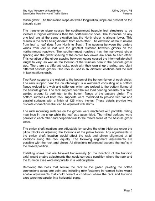
<strong>The</strong> <strong>New</strong> <strong>Woodrow</strong> <strong>Wilson</strong> <strong>Bridge</strong>Span Drive Machinery and Traffic GatesJeffrey D Keyt, PEParsonsfascia girder. <strong>The</strong> transverse slope as well a longitudinal slope are present on thebascule span.<strong>The</strong> transverse slope causes the southernmost bascule leaf structures to belocated at higher elevations than the northernmost ones. <strong>The</strong> trunnions on anyone leaf are at the same elevation but the North girder is always lower. Thisresults in the racks being different from each other. <strong>The</strong> elevation of the trunnionsfrom leaf to leaf rises from North to South. <strong>The</strong> spacing between the girdersvaries from leaf to leaf with the greatest distance between girders on thenorthernmost roadway. <strong>The</strong> southernmost roadway has the narrowest girderspacing and the girder spacing of the center two leaves are equal to each other.This variation of the girder spacing between leaves caused the intermediate shaftlength to vary, as well as the location of the trunnion bore in the bascule girderweb. <strong>The</strong>re are six different racks, each with their own shop drawing, and eightdifferent bascule girders. One rack is used in six different locations and the restin two locations each.Two Rack supports are welded to the bottom of the bottom flange of each girder.<strong>The</strong> rack support near the counterweight is a weldment consisting of a bottomflange welded to a web and stiffeners which are welded to the bottom flange ofthe bascule girder. <strong>The</strong> rack support near the live load bearing consists of a platewelded around its perimeter to the bottom flange of the bascule girder. <strong>The</strong>bottom surfaces of both rack supports were machined to provide two flat andparallel surfaces with a finish of 125 micro inches. <strong>The</strong>se details provide twodiscrete connections that can be adjusted with shims.<strong>The</strong> rack mounting surfaces on the girders were machined with portable millingmachines in the shop while the leaf was assembled. <strong>The</strong> milled surfaces wereparallel to each other and perpendicular to the milled areas of the bascule girderwebs.<strong>The</strong> pinion shaft locations are adjustable by varying the shim thickness under thepillow blocks or adjusting the locations of the pillow blocks. Any adjustments tothe pinion shaft location would affect the rack and pinion alignment at alllocations along the rack equally. <strong>The</strong> following alignment adjustments arepossible with the rack and pinion. All directions referenced assume the leaf is inthe closed position.Installing shims that are beveled transversely (in the direction of the trunnionaxis) would enable adjustments that could correct a condition where the rack andthe trunnion axes were not parallel in a vertical plane.Removing the bolts that secure the rack to the girder, pivoting the boltedconnections about one point and installing new fasteners in reamed holes wouldenable adjustments that could correct a condition where the rack and trunnionaxes were not parallel in a horizontal plane.Page 5


