

The New Woodrow Wilson Bridge - Heavy Movable Structures, Inc.
The New Woodrow Wilson Bridge - Heavy Movable Structures, Inc.
The New Woodrow Wilson Bridge - Heavy Movable Structures, Inc.

You also want an ePaper? Increase the reach of your titles
YUMPU automatically turns print PDFs into web optimized ePapers that Google loves.
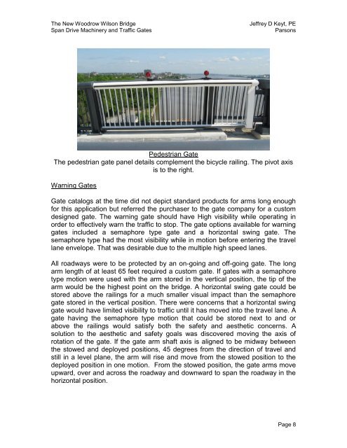
<strong>The</strong> <strong>New</strong> <strong>Woodrow</strong> <strong>Wilson</strong> <strong>Bridge</strong>Span Drive Machinery and Traffic GatesJeffrey D Keyt, PEParsonsPedestrian Gate<strong>The</strong> pedestrian gate panel details complement the bicycle railing. <strong>The</strong> pivot axisis to the right.Warning GatesGate catalogs at the time did not depict standard products for arms long enoughfor this application but referred the purchaser to the gate company for a customdesigned gate. <strong>The</strong> warning gate should have High visibility while operating inorder to effectively warn the traffic to stop. <strong>The</strong> gate options available for warninggates included a semaphore type gate and a horizontal swing gate. <strong>The</strong>semaphore type had the most visibility while in motion before entering the travellane envelope. That was desirable due to the multiple high speed lanes.All roadways were to be protected by an on-going and off-going gate. <strong>The</strong> longarm length of at least 65 feet required a custom gate. If gates with a semaphoretype motion were used with the arm stored in the vertical position, the tip of thearm would be the highest point on the bridge. A horizontal swing gate could bestored above the railings for a much smaller visual impact than the semaphoregate stored in the vertical position. <strong>The</strong>re were concerns that a horizontal swinggate would have limited visibility to traffic until it has moved into the travel lane. Agate having the semaphore type motion that could be stored next to and orabove the railings would satisfy both the safety and aesthetic concerns. Asolution to the aesthetic and safety goals was discovered moving the axis ofrotation of the gate. If the gate arm shaft axis is aligned to be midway betweenthe stowed and deployed positions, 45 degrees from the direction of travel andstill in a level plane, the arm will rise and move from the stowed position to thedeployed position in one motion. From the stowed position, the gate arms moveupward, over and across the roadway and downward to span the roadway in thehorizontal position.Page 8


