M2110 Hardware Reference Manual - MEMSIC
M2110 Hardware Reference Manual - MEMSIC
M2110 Hardware Reference Manual - MEMSIC

Create successful ePaper yourself
Turn your PDF publications into a flip-book with our unique Google optimized e-Paper software.
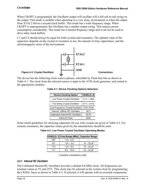
IRIS OEM Edition <strong>Hardware</strong> <strong>Reference</strong> <strong>Manual</strong>When CKOPT is programmed, the Oscillator output will oscillate will a full rail-to-rail swing onthe output. This mode is suitable when operating in a very noisy environment or when the outputfrom XTAL2 drives a second clock buffer. This mode has a wide frequency range. WhenCKOPT is unprogrammed, the Oscillator has a smaller output swing. This reduces powerconsumption considerably. This mode has a limited frequency range and it can not be used todrive other clock buffers.C1 and C2 should always be equal for both crystals and resonators. The optimal value of thecapacitors depends on the crystal or resonator in use, the amount of stray capacitance, and theelectromagnetic noise of the environment.XTAL2XTAL1Figure 4-3. Crystal OscillatorGNDConnectionsThe device has the following clock source options, selectable by Flash fuse bits as shown inTable 4-1. The clock from the selected source is input to the AVR clock generator, and routed tothe appropriate modules.Table 4-1. Device Clocking Options SelectionDevice Clocking OptionCKSEL[3..0]Low Power Crystal Oscillator 1111—1000Full Swing Crystal Oscillator 0111—0110Low-Frequency Crystal Oscillator 0101-0100Internal 128kHz RC Oscillator 0011Calibrated Internal RC Oscillator 0010External Clock 0000Some initial guidelines for choosing capacitors for use with crystals are given in Table 4-2. Forceramic resonators, the capacitor values given by the manufacturer should be used.Table 4-2. Low Power Crystal Oscillator Operating ModesCKSEL[3..1] Freq Range (MHz) Capacitor Range100 † 0.4 - 0.9 -101 0.9 – 3.0 12 – 22 pF110 3.0 – 8.0 12 – 22 pF111 8.0 – 16.0 12 – 22 pF†ceramic resonators only4.3.1 Internal RC OscillatorThe Calibrated Internal RC Oscillator provides a default 8.0 MHz clock. All frequencies arenominal values at 3V and 25°C. This clock may be selected as the system clock by programmingthe CKSEL fuses as shown in Table 4-3. If selected, it will operate with no external components.Page 16Doc. # 7430-0549-01 Rev. A