M2110 Hardware Reference Manual - MEMSIC
M2110 Hardware Reference Manual - MEMSIC
M2110 Hardware Reference Manual - MEMSIC

You also want an ePaper? Increase the reach of your titles
YUMPU automatically turns print PDFs into web optimized ePapers that Google loves.
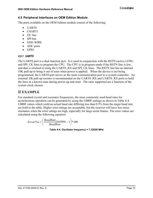
IRIS OEM Edition <strong>Hardware</strong> <strong>Reference</strong> <strong>Manual</strong>4.5 Peripheral Interfaces on OEM Edition ModuleThe ports available on the OEM Edition module consist of the following:• UART0• USART1• I2C bus• SPI bus• ONE-WIRE• ADC ports• GPIO4.5.1 UART0The UART0 port is a dual function port. It is used in conjunction with the RSTN (active LOW)and SPI_CK lines to program the CPU. The CPU is in program mode if the RSTN line is low,and data is clocked in using the UART0_RX and SPI_CK lines. The RSTN line has an internal10K pull-up to bring it out of reset when power is applied. When the device is not beingprogrammed, the UART0 port serves as the main communication port to a system controller. Anexternal 10k pull-up resistor is recommended on the UART0_RX and UART0_RX ports to holdthe lines in a known state during power-up and reset. The rates supported are a function of thesystem clock chosen. EXAMPLEFor standard crystal and resonator frequencies, the most commonly used baud rates forasynchronous operation can be generated by using the UBRR settings as shown in Table 4-4.UBRR values which yield an actual baud rate differing less than 0.5% from the target baud rate,are bold in the table. Higher error ratings are acceptable, but the receiver will have less noiseresistance when the error ratings are high, especially for large serial frames. The error values arecalculated using the following equation:⎛ BaudRateClosestMatch⎞Error(%) = ⎜−1⎟ *100⎝ BaudRate ⎠Table 4-4. Oscillator frequency = 7.32826 MHzDoc. # 7430-0549-01 Rev. A Page 19