M2110 Hardware Reference Manual - MEMSIC
M2110 Hardware Reference Manual - MEMSIC
M2110 Hardware Reference Manual - MEMSIC

Create successful ePaper yourself
Turn your PDF publications into a flip-book with our unique Google optimized e-Paper software.
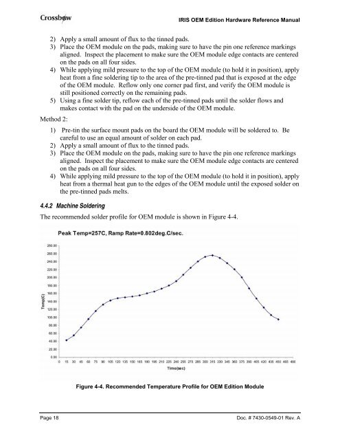
IRIS OEM Edition <strong>Hardware</strong> <strong>Reference</strong> <strong>Manual</strong>2) Apply a small amount of flux to the tinned pads.3) Place the OEM module on the pads, making sure to have the pin one reference markingsaligned. Inspect the placement to make sure the OEM module edge contacts are centeredon the pads on all four sides.4) While applying mild pressure to the top of the OEM module (to hold it in position), applyheat from a fine soldering tip to the area of the pre-tinned pad that is exposed at the edgeof the OEM module. Reflow only one corner pad first, and verify the OEM module isstill positioned correctly on the remaining pads.5) Using a fine solder tip, reflow each of the pre-tinned pads until the solder flows andmakes contact with the pad on the underside of the OEM module.Method 2:1) Pre-tin the surface mount pads on the board the OEM module will be soldered to. Becareful to use an equal amount of solder on each pad.2) Apply a small amount of flux to the tinned pads.3) Place the OEM module on the pads, making sure to have the pin one reference markingsaligned. Inspect the placement to make sure the OEM module edge contacts are centeredon the pads on all four sides.4) While applying mild pressure to the top of the OEM module (to hold it in position), applyheat from a thermal heat gun to the edges of the OEM module until the exposed solder onthe pre-tinned pads melts.4.4.2 Machine SolderingThe recommended solder profile for OEM module is shown in Figure 4-4.Figure 4-4. Recommended Temperature Profile for OEM Edition ModulePage 18Doc. # 7430-0549-01 Rev. A