M2110 Hardware Reference Manual - MEMSIC
M2110 Hardware Reference Manual - MEMSIC
M2110 Hardware Reference Manual - MEMSIC

Create successful ePaper yourself
Turn your PDF publications into a flip-book with our unique Google optimized e-Paper software.
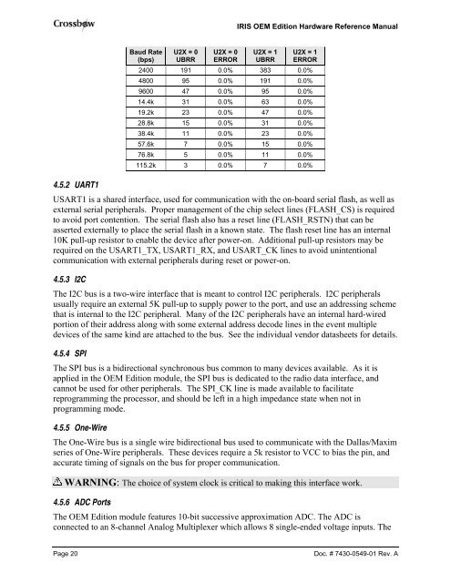
IRIS OEM Edition <strong>Hardware</strong> <strong>Reference</strong> <strong>Manual</strong>4.5.2 UART1Baud Rate(bps)U2X = 0UBRRU2X = 0ERRORU2X = 1UBRRU2X = 1ERROR2400 191 0.0% 383 0.0%4800 95 0.0% 191 0.0%9600 47 0.0% 95 0.0%14.4k 31 0.0% 63 0.0%19.2k 23 0.0% 47 0.0%28.8k 15 0.0% 31 0.0%38.4k 11 0.0% 23 0.0%57.6k 7 0.0% 15 0.0%76.8k 5 0.0% 11 0.0%115.2k 3 0.0% 7 0.0%USART1 is a shared interface, used for communication with the on-board serial flash, as well asexternal serial peripherals. Proper management of the chip select lines (FLASH_CS) is requiredto avoid port contention. The serial flash also has a reset line (FLASH_RSTN) that can beasserted externally to place the serial flash in a known state. The flash reset line has an internal10K pull-up resistor to enable the device after power-on. Additional pull-up resistors may berequired on the USART1_TX, USART1_RX, and USART_CK lines to avoid unintentionalcommunication with external peripherals during reset or power-on.4.5.3 I2CThe I2C bus is a two-wire interface that is meant to control I2C peripherals. I2C peripheralsusually require an external 5K pull-up to supply power to the port, and use an addressing schemethat is internal to the I2C peripheral. Many of the I2C peripherals have an internal hard-wiredportion of their address along with some external address decode lines in the event multipledevices of the same kind are attached to the bus. See the individual vendor datasheets for details.4.5.4 SPIThe SPI bus is a bidirectional synchronous bus common to many devices available. As it isapplied in the OEM Edition module, the SPI bus is dedicated to the radio data interface, andcannot be used for other peripherals. The SPI_CK line is made available to facilitatereprogramming the processor, and should be left in a high impedance state when not inprogramming mode.4.5.5 One-WireThe One-Wire bus is a single wire bidirectional bus used to communicate with the Dallas/Maximseries of One-Wire peripherals. These devices require a 5k resistor to VCC to bias the pin, andaccurate timing of signals on the bus for proper communication.WARNING: The choice of system clock is critical to making this interface work.4.5.6 ADC PortsThe OEM Edition module features 10-bit successive approximation ADC. The ADC isconnected to an 8-channel Analog Multiplexer which allows 8 single-ended voltage inputs. ThePage 20Doc. # 7430-0549-01 Rev. A