M2110 Hardware Reference Manual - MEMSIC
M2110 Hardware Reference Manual - MEMSIC
M2110 Hardware Reference Manual - MEMSIC

Create successful ePaper yourself
Turn your PDF publications into a flip-book with our unique Google optimized e-Paper software.
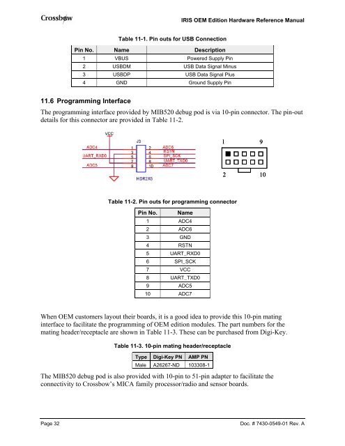
IRIS OEM Edition <strong>Hardware</strong> <strong>Reference</strong> <strong>Manual</strong>Table 11-1. Pin outs for USB ConnectionPin No. Name Description1 VBUS Powered Supply Pin2 USBDM USB Data Signal Minus3 USBDP USB Data Signal Plus4 GND Ground Supply Pin11.6 Programming InterfaceThe programming interface provided by MIB520 debug pod is via 10-pin connector. The pin-outdetails for this connector are provided in Table 11-2.1 92 10Table 11-2. Pin outs for programming connectorPin No. Name1 ADC42 ADC63 GND4 RSTN5 UART_RXD06 SPI_SCK7 VCC8 UART_TXD09 ADC510 ADC7When OEM customers layout their boards, it is a good idea to provide this 10-pin matinginterface to facilitate the programming of OEM edition modules. The part numbers for themating header/receptacle are shown in Table 11-3. These can be purchased from Digi-Key.Table 11-3. 10-pin mating header/receptacleType Digi-Key PN AMP PNMale A26267-ND 103308-1The MIB520 debug pod is also provided with 10-pin to 51-pin adapter to facilitate theconnectivity to Crossbow’s MICA family processor/radio and sensor boards.Page 32Doc. # 7430-0549-01 Rev. A