MET ONE 3400 Series Portable Airborne Particle ... - Particle Counters
MET ONE 3400 Series Portable Airborne Particle ... - Particle Counters
MET ONE 3400 Series Portable Airborne Particle ... - Particle Counters

Create successful ePaper yourself
Turn your PDF publications into a flip-book with our unique Google optimized e-Paper software.
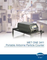
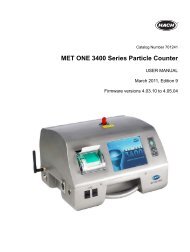
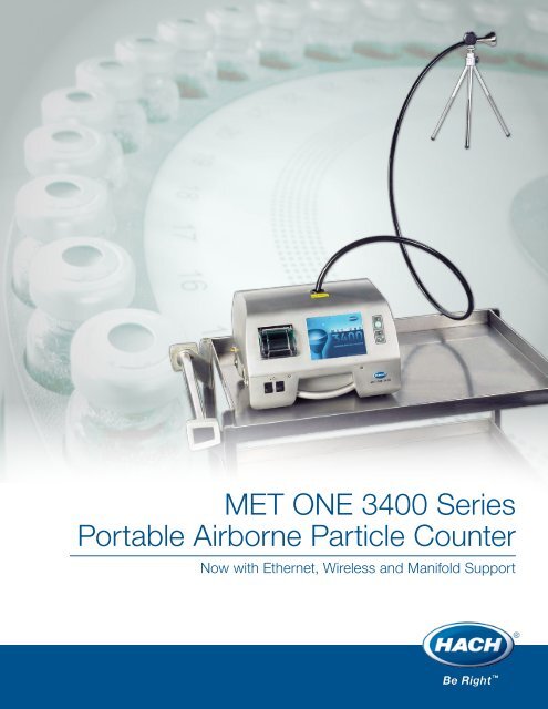
<strong>MET</strong> <strong>ONE</strong> <strong>3400</strong> <strong>Series</strong><strong>Portable</strong> <strong>Airborne</strong> <strong>Particle</strong> CounterNow with Ethernet, Wireless and Manifold Support
<strong>MET</strong> <strong>ONE</strong> <strong>3400</strong> SERIESPORTABLE AIRBORNE PARTICLE COUNTERFlexible communicationsWireless, Ethernet, Serial and USBCompliance set up wizardA few clicks to complianceSeamless connectivity to datamanagement softwareOPC Server enabled opencommunication architectureIntuitive user interfaceEasy area, location, operating parameterconfiguration and replicationMet One <strong>3400</strong> Sereasier air sampltransferring that s
ies portable particle counters offering, data capturing, processing andave hours of valuable operator time21 CFR Part 11 complianceSecure multi-level log onUnit-to-unit accuracyand reproducibilityAssured through ISO 21501 complianceLong continuous operationDual hot-swappable batteriesWith flexible communication options and an open communication architecture, the <strong>MET</strong> <strong>ONE</strong> <strong>3400</strong>can be seamlessly integrated into a central environmental monitoring system eliminating the needfor manual record keeping. Intuitive operating commands and test wizard rich user interfacesoftware, Long Life Laser technology, and long continuous operation capability, enable the<strong>MET</strong> <strong>ONE</strong> <strong>3400</strong> to reliably perform cleanroom validation testing and critical process monitoringwithin the shortest possible time.The <strong>MET</strong> <strong>ONE</strong> <strong>3400</strong> also features 21 CFR Part 11 compliance, easy data download, regulatorystandard compliant analysis and reporting functions, strategically placed carrying handles andan easy-to-wipe down stainless-steel surface.
The right people with the experienceand expertise you need.ServiceRobustness and ease of use is addressed in the design anddevelopment of every Hach instrument. Nevertheless, even thefinest instruments require care and attention. To meet this need, Hachhas developed the most comprehensive network of service centersand certified agents in the industry. This global networkoffers on-site service and calibration support as well as localbench service facilities.At Hach, it’s about learningfrom our customers andproviding the right answers.Keep it pure.Make it simple.Be right.At Hach, we provide coverage for every aspect of the system frominstallation and calibration to data analysis and audits. In addition,comprehensive IQ/OQ documentation and on-site support cansignificantly reduce validation time. Hach service contracts keepyour equipment in compliance and operating at peak performanceto minimize downtime.• Service partnership programs: Our all-inclusiveagreements for service and support provide confidenceand security for your operations.• In-factory services: Including warranty and repairservices, check-up and calibration, and service loaners.• On-site services: Including warranty and field repairwork, start-up and installation services, trainingand preventive maintenance plans.• Custom service programs: For your unique requirements.For current price information,technical support, and orderingassistance, contact the Hachoffice or distributor servingyour area.In the United States, contact:HACH COMPANY World HeadquartersPO Box 608Loveland, Colorado 80539 USATelephone: 800-866-7889Fax: 970-461-3914E-mail: orders@hach.comwww.hach.comU.S. exporters and customers inCanada, Latin America, sub-SaharanAfrica, Asia, and Australia/New Zealand, contact:HACH COMPANY World HeadquartersPO Box 608Loveland, Colorado 80539 USATelephone: 970-663-9760Fax: 970-461-3914E-mail: intl@hach.comwww.hach.comIn Europe, the Middle East, andMediterranean Africa, contact:HACH LANGE GmbHWillstätterstraße 11D-40549 Düsseldorf, GERMANYTel: +49 (0) 211 5288-0Fax: +49 (0) 211 5288-143E-mail: info@hach-lange.dewww.hach-lange.comLit. No. BR-<strong>3400</strong>-US-0109. Printed in USA. © Hach Company 2009. All rights reserved.In the interest of improving and updating its equipment, Hach Company reserves the right to alter specifications to equipment at any time.
Training Manual<strong>MET</strong> One <strong>3400</strong> <strong>Series</strong><strong>Portable</strong> <strong>Airborne</strong> <strong>Particle</strong> Counter
Product Details
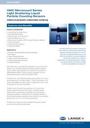
Data SheetMet One <strong>3400</strong> <strong>Series</strong><strong>Portable</strong> <strong>Airborne</strong><strong>Particle</strong> CounterFeatures and BenefitsFlexible CommunicationsWireless, Ethernet and Serial Communication options provideeasy integration to any environmental monitoring softwareTest Wizard for Easier ComplianceTest wizard and necessary documentation help in complying toISO, FDA and EU standards - saves time and labor for planning,sampling and processing raw count dataSeamless Connectivity to Data Management SoftwareOPC Server enabled open communication architecturereduces cost of integration to commonly used industrialdata management softwareIntuitive User InterfaceEasy area, location and operating parameter configuration andreplication saves operator time for setting and running the counterMultiple User Log-inPassword protected multi-level user access to instrumentprovides data security for 21 CFR Part 11 complianceISO 21501-4 ComplianceDesigned for full ISO 21501-4 calibration compliance providingunit-to-unit accuracy and reproducibilityLong Life LaserLong Life Laser diode with 10-year MTTF reduces costof ownershipWith flexible communication options and an opencommunication architecture, the <strong>MET</strong> <strong>ONE</strong> <strong>3400</strong> canbe seamlessly integrated into a central environmentalmonitoring system eliminating the need for manualrecord keeping. Intuitive operating commands and testwizard rich user interface software, Long Life Lasertechnology, and long continuous operation capability,enable the <strong>MET</strong> <strong>ONE</strong> <strong>3400</strong> <strong>Series</strong> to reliably performcleanroom validation testing and critical processmonitoring within the shortest possible time.The <strong>MET</strong> <strong>ONE</strong> <strong>3400</strong> also features 21 CFR Part 11compliance, easy data download, regulatorystandard compliant analysis and reportingfunctions, strategically placed carrying handlesand an easy-to-wipe down stainless-steel surface.Use the <strong>MET</strong> <strong>ONE</strong> <strong>3400</strong> particle counter forcleanroom validation as a stand alone unit, asemi-continuous process monitoring with manifoldsystem, or an on-line continuous process monitoringsystem by integrating to an environment monitoringsoftware. The <strong>MET</strong> <strong>ONE</strong> <strong>3400</strong> can do it all.Manifold SupportSupport of Met One 2432 manifold provides low costsemi-continuous monitoring optionHot-Swappable BatteriesLong battery life between charges results in longer instrumentavailability. Hot-swappable batteries eliminate the need forpowering down, zero counting and powering back upSelectable ChannelsStraightforward selectable 8-channel option for easy filter testingHach ServiceOn site service, calibration support and service contractsto keep your equipment in compliance®
SpecificationsStandard Size Channels 3413 and 3423 0.3, 0.5, 1.0, 3.0, 5.0, 10.0* µm3415 and 3425 0.5, 1.0, 2.0, 3.0, 5.0, 10.0or 0.5, 1.0, 2.0, 3.0, 5.0, 25.0* µmFlow Rate 3413 and 3415 28.3 LPM (1.0 CFM) ± 5% (default factory setting)3423 and 3425 50 LPM (1.77 CFM) ± 5% (default factory setting)Zero CountConforms to JIS B9921. 1 count or less in 5 minutes, 95% confidence levelCoincidence Loss 28.3 LPM (1.0 CFM) 5% at 14,126,000 particles/m 3 (400,000 particles/ft 3 )50 LPM (1.77 CFM) 5% at 4,000,000 particles/m 3 (113,266 particles/ft 3 )Counting Efficiency 3413 and 3423 50%±20% for 0.3 µm, (100%±10% at 1.5 times theminimum sensitivity), fully complies with ISO 21501-43415 and 3425 50%±20 for 0.5 µm, (100%±10% at 1.5 times theminimum sensitivity), fully complies with ISO 21501-4Light SourceLong Life Laser diode with 10-year Mean Time To Failure (MTTF)Pump TypeAir vacuum, rated for continuous useCount DisplayColor 1/4 VGA TFT Touch ScreenInterfaceWindows CE ® -basedSample/Hold/Delay Times 1 second to 23 hrs 59 min 59 secCount Alarms1 to 9,999,999 countsCount CyclesUp to 100 while in automatic modeManifoldSupports 2432 32-port Manifold SystemLocation Labels0 to 999, appears on printoutData Storage5,000 samples, scrollable on Historical Data review screenCommunication Interfaces RS232, RS485, 802.11 b/g Wireless, 802.3 Ethernet,USB Client (Version 1.1), USB Host (Version 1.1)Communication Protocol Modbus TCP, Modbus RTU, Serial FXBattery TypeLithium ion smart battery; rechargeable, ejectable and hot-swappableOperating Time (Battery) 28.3 LPM (1.0 CFM) 6 hours**50 LPM (1.77 CFM) 7 hours**Battery Recharge Time 6.75 hours minimum, 10 hours maximumPower24 VDC 3.2A with 100~240 VAC 50/60 Hz adapter (included in ship kit)Size Dimensions31.8 W x 25.4 D x 20.3 H cm (12.5 x 10 x 8 inches)Weight (without battery) 3413 and 3415 7.55 kg (16.6 lbs)3423 and 3425 8.33 kg (18.3 lbs)Enclosure Material Stainless SteelEnvironment Operating 0 to 40° C (32 to 104° F),10 to 90% relative humidity, non-condensingStorage-40 to 50° C (-40 to 122° F),0 to 98% relative humidity, non-condensingWarranty2 years (instrument), 3 years (Long Life Laser diode)When ordering, specify Basic Sensitivity 0.3 to 10 µm (3413 or 3423) or0.5 to 10.0 µm or 0.5 to 25.0 µm (3415 or 3425)Selectable Channel Option Choose up to 8 sizes from 0.3 to 25.0 µm*Flow Rate28.3 LPM (1.0 CFM) (3413 or 3415) or50 LPM (1.77 CFM) (3423 or 3425)Wireless OptionDenote part number ending with WAccessories Included Isokinetic Probe (aluminum) Zero Count FilterNozzle Cleaning Brush PortAll Version 2 Trial SoftwareFlash Memory DriveAC Power Cord2 Rolls Printer Paper 1 Lithium Ion Smart BatteryOperator Manual0.825 cm (0.325”) I.D. Hytrel ® TubingZero Count FilterStylus for Touch ScreenOptions Zero Count Filter Relative Humidity/TemperaturePortAll Version 2 Software Case with Wheels and Foam InsertAir Velocity SensorLithium Ion Smart BatterySmart Battery Charger Isokinetic Probe (stainless steel)IQ/OQ Validation Protocol Filter Scanning Probe, non-electronicHigh Pressure Diffuser 0.825 cm (0.325 inches) I.D. Hytrel TubingSensor Flash Memory Drive USB to RS-485 or USB to RS-232 ConverterMet One 2432 32-port Manifold Selectable 8-channel optionAt Hach, it’s aboutlearning from ourcustomers andproviding the rightanswers.Keep it pure.Make it simple.Be right.For current priceinformation, technicalsupport, and orderingassistance, contact theHach office or distributorserving your area.In the United States, contact:HACH COMPANY World HeadquartersPO Box 608Loveland, Colorado 80539 USATelephone: 800-866-7889Fax: 970-461-3914E-mail: orders@hach.comwww.hach.comU.S. exporters and customers inCanada, Latin America, sub-SaharanAfrica, Asia, and Australia/New Zealand, contact:HACH COMPANY World HeadquartersPO Box 608Loveland, Colorado 80539 USATelephone: 970-663-9760Fax: 970-461-3914E-mail: intl@hach.comwww.hach.comIn Europe, the Middle East, andMediterranean Africa, contact:HACH LANGE GmbHWillstätterstraße 11D-40549 Düsseldorf, GERMANYTel: +49 (0) 211 5288-0Fax: +49 (0) 211 5288-143E-mail: info@hach-lange.dewww.hach-lange.com* Channel selections can be selected at time of order in a range from 0.3 µm to 25 µm. However 0.3 µm and 25 µm cannot be configured together.** Battery life is estimated with these conditions: The 1.77 cfm unit sampling for 20 minutes (1 m 3 ) sample, print record, a 5-minute hold time (simulating move to newlocation), then repeat this cycle. Backlight sleep time is set at 2 minutes. The 1.0 cfm unit, sample time is set at one minute, print record, a 1-minute hold time(simulating continuous sampling mode), then repeat this cycle. Backlight would remain on at all times.Lit. No. DS-<strong>3400</strong>-US-1208. Printed in USA. © Hach Company 2008. All rights reserved.In the interest of improving and updating its equipment, Hach Company reserves the right to alter specifications to equipment at any time.®
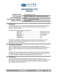
PROPOSALPrepared for:Contact:Phone:E-mail:Quote No.:Prepared by:Phone:E-mail:Date:Quote Expires on:<strong>MET</strong> <strong>ONE</strong> <strong>3400</strong> SERIESAIRBORNE PARTICLE COUNTING SYSTEM
SUMMARY OF NEEDSDear Customer,It was nice to talk to you the other day and discuss your particle counting requirements.RECOMMENDED SOLUTIONI am pleased to offer you the <strong>MET</strong> <strong>ONE</strong> <strong>3400</strong> for your air monitoring. With numerous installations, our <strong>MET</strong> <strong>ONE</strong> <strong>3400</strong>is the standard for the industry. Here are some of the benefits that we offer:Benefits of Selecting <strong>MET</strong> <strong>ONE</strong> <strong>3400</strong> <strong>Series</strong>:Flexible CommunicationsWireless, Ethernet and Serial Communication options provideeasy integration to any environmental monitoring softwareTest Wizard for Easier ComplianceTest wizard and necessary documentation help in complying toISO, FDA and EU standards - saves time and labor for planning,sampling and processing raw count dataSeamless Connectivity to Data Management SoftwareOPC Server enabled open communication architecturereduces cost of integration to commonly used industrialdata management softwareIntuitive User InterfaceEasy area, location and operating parameter configuration andreplication saves operator time for setting and running the counterMultiple User Log-inPassword protected multi-level user access to instrumentprovides data security for 21 CFR Part 11 complianceISO 21501-4 ComplianceDesigned for full ISO 21501-4 calibration compliance providingunit-to-unit accuracy and reproducibilityLong Life LaserLong Life Laser diode with 10-year MTTF reduces costof ownershipManifold SupportSupport of Met One 2432 manifold provides low costsemi-continuous monitoring optionHot-Swappable BatteriesLong battery life between charges results in longer instrumentavailability. Hot-swappable batteries eliminate the need forpowering down, zero counting and powering back upSelectable ChannelsStraightforward selectable 8-channel option for easy filter testingANATEL HIAC <strong>MET</strong> <strong>ONE</strong> ORBISPHERE
PDiodePDiodePDiodePDiodePRICING QUOTATION<strong>MET</strong> <strong>ONE</strong> <strong>3400</strong> <strong>Series</strong> <strong>Portable</strong> <strong>Airborne</strong> <strong>Particle</strong> CounterQty. Part Number Description Unit Price Extended Price2088900-112088900-12Model 3423, 1.77 CFM (50 LPM) flow rate particlecounterSize channels: 0.3, 0.5, 1.0, 3.0, 5.0, 10 µmTMLight source; Long Life LaserP with 10-year MTTFModel 3425, 1.77 CFM (50 LPM) flow rate particlecounterSize channels: 0.5, 1.0, 2.0, 3.0, 5.0, 10 µmTMLight source; Long Life LaserP with 10-yearMTTF$10,388.00$9,583.002088900-11-W2088900-12-WModel 3423, 1.77 CFM (50 LPM) flow rate particlecounterSize channels: 0.3, 0.5, 1.0, 3.0, 5.0, 10 µmTMLight source; Long Life LaserP with 10-year MTTF Wireless communicationModel 3425, 1.77 CFM (50 LPM) flow rate particlecounterSize channels: 0.5, 1.0, 2.0, 3.0, 5.0, 10 µmTMLight source; Long Life LaserP with 10-yearMTTF Wireless communication$11,088.00$10,283.002082698-05Special 2 size channel option 0.5 & 5.0µ only (mustbe listed on the purchase order as an additional lineitem)$0.002082698-31Special custom sizing between 0.3 & 10µ (must belisted on the purchase order as an additional line itemwith all six sizes specified)$335.002084045-02PortAll Software Kit Version 2.X, data downloadand counting event-scheduling utility. IncludesCD and Manual$0.00700011-22 PortAll License 21 CFR part 11 compliant $790.00700011-21 PortAll License standard version $579.00Included Accessories, one per systemPart NumberDescription2087967-01 Isoprobe 50 LPM AL 1/2 Barb, <strong>MET</strong> <strong>ONE</strong> 3423-3425480-100-0004 Tubing, sample, 1/2” ID, 10 ft, <strong>MET</strong> <strong>ONE</strong> 3423-34252088035-01 Isoprobe Adapter, AL701241 Manual, Owners Operating230-300-7024 Power Supply, +24 VDC @ 3A400105 Power Cord, 115 VACANATEL HIAC <strong>MET</strong> <strong>ONE</strong> ORBISPHERE
510667 Power Cord, 220 VAC2087939-01 Zero Count Filter (1.0 CFM models)460519 Printer paper, 2 rolls280-120-2024 Battery pack, smart lithium ion210-400-5171 Stylus Touch screen instrument995240 Cleaning brush, stainless steel2088010-01 USB memory drive 128M490-200-0001 Wireless AntennaANATEL HIAC <strong>MET</strong> <strong>ONE</strong> ORBISPHERE
OPTIONAL ACCESSORIESOptional AccessoriesPart Number Description Unit Price2087966-02 Isokinetic probe 1.00 CFM SS 3/8 Barb $130.002088035-02 Isokinetic probe Tripod Adapter kit SS $295.00460-400-4798 Cable, USB 2.0, Hi speed 1Meter $18.00826172 Air Velocity Probe, 0 – 200 FPM $664.00460519 Printer Paper (price per roll) $7.00280-300-5000 Smart Battery Charger $664.00280-120-2024 Battery, Smart Lithium Ion $754.002086719-01 Temperature & Relative Humidity Probe $299.00701241-01 Validation Documentation (IQ/OQ) CD $1,671.00X-VAL<strong>3400</strong>-1YR-1VST On-site Validation Service (must include a zone charge) $2,650.002084045-02PortAll Software Kit Version 2.X, data download and countingevent-scheduling utility. Includes CD and Manual$0.00700011-22 PortAll License 21 CFR Part 11 compliant $814.00700011-21 PortAll License Standard edition $579.00701169-01 PortAll Validation Documentation (IQ/OQ) CD $1,170.002088028 Carrying/Shipping Case w/ wheels and pull-out handle $945.002088000-01 Filter scanning probe (with electronics) 1 CFM $1,087.002088000-02 Filter scanning probe (w/o electronics) 1 CFM $919.002088012-02Adapter, USB to RS-232, USB cable, DB-9 null modemand Modbus register map$50.002088012-01 Adapter, USB to RS-485, USB cable and Modbus register map $114.002080732-8 High Pressure Diffuser for use with 1.0 CFM units $1,387.002080732-9 High Pressure Diffuser for use with 50 LPM units $2,610.002087919-01<strong>3400</strong> Spares KitIncludes: 2 ea Smart Battery charger2 ea Lithium Smart Battery4 ea Thermal Printer Paper rolls1 ea Flash Drive/Stylus Combination$2,498.00ANATEL HIAC <strong>MET</strong> <strong>ONE</strong> ORBISPHERE
SERVICE OPTIONSService OptionsOur Service Agreement Program offers you the peace of mind of knowing that industry experts are partnering with you to keepyour instrumentation well maintained. Our service processes involve more than just accurate and efficient calibration. Theyalso incorporate updates to instruments, adjustments and modifications that are not part of the calibration process. Our teamof factory-certified field service engineers is happy to support you with knowledgeable answers to your questions while onsiteto perform your service. Hach Company also employs a team of certified professionals at the factory and depot service centersif you send your instrument in for calibration.Additional Benefits of Coverage Include:• Prescheduled Onsite Service Visits to ensure that your service meets the requirement dates• Priority Bench Service at our factory or depot locations• 15% Parts and Labor Discount for Services Performed During The Coverage period• As Received Data provided at no additional charge – a $156.00 value per instrumentIf you would like to combine the service with your other instruments, please contact us to quote.Part Number Service Description Unit PriceTotal =ANATEL HIAC <strong>MET</strong> <strong>ONE</strong> ORBISPHERE
SPECIFICATIONSStandard Size Channels 3413 and 3423 0.3, 0.5, 1.0, 3.0, 5.0, 10.0 µ3415 and 3425 0.5, 1.0, 2.0, 3.0, 5.0, 10.0or 0.5, 1.0, 2.0, 3.0, 5.0, 25.0* µFlow Rate3413 and 3415 28.3 LPM (1.0 CFM) ± 5% (default factory setting)3423 and 3425 50 LPM (1.77 CFM) ± 5% (default factory setting)Zero Count Conforms to JIS B9921. 1 count or less in 5 minutes, 95%confidence levelCoincidence Loss 28.3 LPM (1.0 CFM) 5% at 14,126,000 particles/m3 (400,000particles/ft3)50 LPM (1.77 CFM) 5% at 4,000,000 particles/m3 (113,266particles/ft3)Counting EfficiencyLight SourcePump TypeCount DisplayInterfaceSample/Hold/Delay TimesCount AlarmsCount CyclesManifoldLocation LabelsData StorageCommunication InterfacesCommunication ProtocolBattery TypeOperating Time (Battery)Battery Recharge Time3413 and 3423 50%±20% for 0.3 µ, (100%±10% at 1.5 times theminimum sensitivity), fully complies with ISO 21501-43415 and 3425 50%±20 for 0.5 µ, (100%±10% at 1.5 times theminimum sensitivity), fully complies with ISO 21501-4Long Life Laser diode with 10-year Mean Time To Failure (MTTF)Air vacuum, rated for continuous useColor 1/4 VGA TFT Touch ScreenWindows CE®-based1 second to 23 hrs 59 min 59 sec1 to 9,999,999 countsUp to 100 while in automatic modeSupports 2432 32-port Manifold System0 to 999, appears on printout5,000 samples, scrollable on Historical Data review screenRS232, RS485, 802.11 b/g Wireless, 802.3 Ethernet,USB Client (Version 1.1), USB Host (Version 1.1)Modbus TCP, Modbus RTU, Serial FXLithium ion smart battery; rechargeable, ejectable and hotswappable28.3 LPM (1.0 CFM) 6 hours**50 LPM (1.77 CFM) 7 hours**6.75 hours minimum, 10 hours maximumANATEL HIAC <strong>MET</strong> <strong>ONE</strong> ORBISPHERE
PowerSize, DimensionsWeight (without battery)Enclosure MaterialEnvironmentWarranty24 VDC 3.2A with 100~240 VAC 50/60 Hz adapter (included inship kit)31.8 W x 25.4 D x 20.3 H cm (12.5 x 10 x 8 inches)3413 and 3415 7.55 kg (16.6 lbs)3423 and 3425 8.33 kg (18.3 lbs)Stainless SteelOperating 0 to 40° C (32 to 104° F),10 to 90% relative humidity, non-condensingStorage -40 to 50° C (-40 to 122° F),0 to 98% relative humidity, non-condensing2 years (instrument), 3 years (Long Life Laser diode)* Channel selections can be selected at time of order in a range from 0.3 µ to 25 µ. However 0.3 µ and 25 µ cannot be configured together.** Battery life is estimated with these conditions: The 1.77 cfm unit sampling for 20 minutes (1 m3) sample, print record, a 5-minute hold time(simulating move to new location), then repeat this cycle. Backlight sleep time is set at 2 minutes. The 1.0 cfm unit, sample time is set at oneminute, print record, a 1-minute hold time (simulating continuous sampling mode), then repeat this cycle. Backlight would remain on at all times.ANATEL HIAC <strong>MET</strong> <strong>ONE</strong> ORBISPHERE
TERMS OF SALETerms of SaleDelivery: 2 weeks AROPayment Terms: Net 30-days OACFreight: 3-day Prepay & AddFOB: Origin• Please reference the quotation number on your purchase order• Sales tax is not included in this quote. Applicable sales tax will be added to the invoice based on the U.S. destination.If applicable provide a valid resale/exemption certificate.• Packing and either Fed-Ex or UPS 3-day freight charges will be added unless otherwise specified.• Pricing included in the quotation applies to domestic sales only. The equipment quoted operates with standardU.S. supply voltages.• Buyer is to advise Hach Company of the final destination of the equipment at the time of purchaseto validate the warranty coverage.• Hach Company standard terms and conditions apply to all salesThank you for the opportunity to provide this quotation. Please do not hesitate to contact us with any questions.THACH COMPANYP.O. Box 608Loveland, CO 80539 U.S.A.Ph: 970-663-9760Toll Free: 800-866-7889Order E-mail: orders@hach.comOrder Fax: 970-461-3914ANATEL HIAC <strong>MET</strong> <strong>ONE</strong> ORBISPHERE
Statement of CalibrationJuly 11, 2008HachGrants Pass, OregonPreface:At Hach, we build airborne and liquid particle counters used to monitor contamination inclean rooms, water systems, and hydraulic oil systems. We also provide such accessoriesas temperature and humidity probes and air velocity probes. Our factory is located inGrants Pass, Oregon. We have a service facility in Grants Pass and field service officesthroughout the United States and world-wide.Hach strives for total customer satisfaction. Our products are built, serviced, andcalibrated by trained and certified associates. All drawings and procedures are controlledin our document control system. We maintain current revisions of foreign and domesticstandards, and use these and other industry-accepted practices to build, service, andcalibrate our products.All work is performed per the requirements outlined in our Quality Manual, QA1001. Weare ISO9001:2000 certified, and we comply with ISO 17025. All standards, testequipment, and calibration particles are traceable to National Institute of Science andTechnology (NIST).form 011169July 11, 20081 of 4
<strong>Particle</strong> Counter Calibration:<strong>Airborne</strong>:At Hach, we use a calibration method known in the industry as size calibration on ourairborne products. This method is outlined in JIS B 9921, ASTM F328, IEST-RP-CC014.1, and ISO 21501-4. As there are no airborne artifacts (particle standards)available, NIST-traceable polystyrene spheres and pulse height analyzer (PHA) are usedin the size calibration. Other NIST-traceable test equipment is used as necessary tocomplete the calibration.Once the size calibration is complete, a calibration curve is produced, and each channel isoptimized for the proper size. This is required because often the NIST-traceable spheresaren’t the exact channel size (for example 0.299 um spheres may be used to calibrate a0.3 um channel).The entire calibration process is controlled by a wizard-driven utility known as Core Cal,which was developed by this company. The software provides consistency and increasedcalibration accuracy. Core Cal also incorporates data retention and generation ofcalibration certificates.The calibration includes a counting efficiency test which compares the counter beingcalibrated (UUT) with a 100% transfer standard.The transfer standard is calibrated using a Condensation Nucleus Counter (CNC),Electrostatic Classifier, and NIST-traceable spheres.In addition to the normal Hach calibration, we also offer complete and partial ISO 21501-4 calibrations.Hach products are calibrated to maintain a counting efficiency of 50 +/- 20% in thesmallest channel, and 100 +/- 10% at 1.5 to 2 times the smallest channel size. Thesetolerances are outlined in the above mentioned standards.Calculated particle size uncertainty is 4% (k=2).Liquid:Liquid sensors are normally size calibrated using NIST-traceable polystyrene spheresusing industry-accepted methods as outlined in JIS B 9925, ASTM F658, and ISO 21501-2/3.The sensor calibration is controlled by a wizard-driven utility known as Core Cal, whichwas developed by this company. The software provides consistency and increasedcalibration accuracy. Core Cal also incorporates data retention and generation ofcalibration certificates.form 011169July 11, 20082 of 4
A liquid system calibration is performed by connecting the sensor to a counter and a flowcontrol system while using NIST-traceable calibration fluid with particles of a knownsize and particle density. Software packages associated with various products are used toaid with the calibration process.Special Calibrations:Although our normal calibration is adequate for most customers, occasionally a specialneed may arise. Submit special requests through our Customer service department.Standards:ISO 9001:2000ISO/IEC 17025:2005(E) General requirements for the competence of testing andcalibration laboratoriesISO 21501 Determination of particle size distribution – Single particle light interactionmethods-2:2007(E) Light scattering liquid-borne particle counter-3:2007(E) Light extinction liquid-borne particle counter-4:2007(E) Light scattering airborne particle counter for clean spacesIEST-RP-CC014.1 Calibration and Characterization of Optical <strong>Airborne</strong> <strong>Particle</strong><strong>Counters</strong>ANSI/NCSL A540-1-1994 Calibration Laboratories and Measuring and Test Equipment-General RequirementsASTM F 328 – 98 (Withdrawn 2007) Standard Practice for Calibration of an <strong>Airborne</strong><strong>Particle</strong> Counter Using Monodisperse Spherical <strong>Particle</strong>sASTM F 658 – 00a Standard Practice for Calibration of a Liquid-Borne <strong>Particle</strong> CounterUsing an Optical System Based Upon Light ExtinctionJIS B 9921:1997 Japanese Industrial Standard: Light scattering automatic particle counterJIS B 9925-1991 Japanese Industrial Standard: Light scattering automatic particle counterfor liquidform 011169July 11, 20083 of 4
<strong>Airborne</strong>Liquidform 011169July 11, 20084 of 4
Technical Papers
Revision to Annex 1:Impact on <strong>Airborne</strong> <strong>Particle</strong> Counting MethodologyEU GMP, Volume 4, Annex 1:Manufacture of Sterile Medicinal ProductsEffective Date: 01 March 20091. OverviewAnnex 1 is a guidance document associated with the European GMP regarding theproduction of Sterile Medicinal Products. The most recent revision of Annex 1 has aneffective date of 01 March 2009 but because of the relaxation of the count limits at 5microns, many customers are adopting it early. There are several key points about therevision that will affect - and in general simplify - the methodology of non-viable airborneparticle counting:a) direct statements of requirements for classification versus monitoringb) linkage to ISO 14644 for classification proceduresc) relaxation of the limits of 5 micron airborne particles allowed in Grade A and Grade Bd) clarification of the need for “continuous” monitoring during production processe) clarification of the sample volume and rates needed during production processThe result is that the concern with a larger sampling volume of one cubic meter appliesspecifically to Grade A areas and only during classification procedures, which, following ISO14644-1, would typically occur only every 6 months. Also the monitoring protocol is clarifiedto allow any sampling rate or sampling volume as long as the process would capturesignificant transient events or system deterioration.2. Specific changes or additions2.1 Direct statements of requirements for classification versus monitoring2.1.1 Separate sections in the document for classification and monitoringNote that the sub-title ofClean room and clean air device classificationprecedes Section 4 through Section 7 whereas the information starting with Section 8through Section 20 is entitledClean room and clean air device monitoring2.1.2 classification differentiated from monitoring“Classification should be clearly differentiated from operational process environmental monitoring”[Section 4]Author: Joe Gecsey Page 1 of 7 01 June 2008
2.2 New classification limits for airborne particles2.1 The table previously wasAt RestIn OperationGradeMaximum permitted number of particles/m 3 equal to or above0.5 µm 5 µm 0.5 µm 5 µmA 3 500 1 3 500 1B 3 500 1 350 000 2 000C 350 000 2 000 3 500 000 20 000D 3 5000 000 20 000 not defined not defined2.2 The newly revised table of classification limits isAt RestIn OperationGrade Maximum permitted number of particles/m 3 equal to or above0.5 µm 5 µm 0.5 µm 5 µmA 3 520 20 3 520 20B 3520 29 352 000 2 900C 352 000 2 900 3 520 000 29 000D 3 520 000 29 000 not defined not defined2.3 Linkage to ISO 14644-1 for classification procedures2.3.1 Section 4 - statement of linkage“Clean rooms and clean air devices should be classified in accordance with ISO 14644-1.” [Section 4]2.3.2 Additional references to ISO 14644-1“ For classification purposes EN/ISO 14644-1 methodology defines both the minimum number of samplelocations and the sample size based on the class limit of the largest considered particle size and themethod of evaluation of the data collected.” [Section 5]2.4 For classification of Grade A areas, a full cubic meter of sampled air required2.4.1 Minimum Sample Volume for Grade A“For classification purposes in Grade A zones, a minimum sample volume of 1m 3 should be taken persample location.” [Section 5]Author: Joe Gecsey Page 2 of 7 01 June 2008
2.5 Process conditions for classification of “in operation” status2.5.1 Three potential activity states can qualify for “in operation” test conditions:a) normal operationsb) simulated operationsc) media fills“ “In operation” classification may be demonstrated during normal operations, simulated operations orduring media fills as worst-case simulation is required for this.” [Section 7]2.6 Establishing a program for monitoring during process2.5.1 Use both results of previous testing and risk analysis to determine positions“Clean rooms and clean air devices should be routinely monitored in operation and the monitoringlocations based on a formal risk analysis study and the results obtained during the classification ofrooms and/or clean air devices.” [Section 8]3. Analysis3.1 Classification follows ISO 14644-1 except for Grade A3.1.1 Frequency of classificationFollowing current ISO 14664-1 and 14644-2 directives, the classification effort needs to bedone at a minimum frequency of every 6 months in Grade A and B areas and every 12months for Grade C and D areas.3.1.2 Minimum number of sample points for classificationThe number of points will be determined by the area of the area to be classified. Theformula is to take the square root of the area (in square meters) and then to round up to thenext whole number. For example, a 200 square meter area would infer a minimum of 15sample positions because the square root of 200 is 14.14 and rounding up to the nextinteger yields a value of 15.3.1.3 Minimum sample volume for classificationBecause the classification effort is based on representative sampling, a minimum volume isspecified in ISO 14644-1 Annex B in order to obtain a reasonable level of confidence thatthe sampled volume reflects - as a partial sample - the entire air quality in that immediatearea. In ISO 14644-1 Annex B, there are calculations for a minimum sample volume.However, this revision of Annex 1 gives specific instructions for the size of the samplevolume used for classification purposes. Revised Annex 1, Section 5, specifically demandsthat the sample volume for classification purposes for Grade A areas be at least one cubicmeter. This is a different volume than is required by following ISO 14644-1 but is consideredappropriate in order to achieve a high level of confidence that the sample results willeffectively represent these critical areas.The table below represents the results of calculating the required minimum sample volumesfor each of the ISO Classes at the respective particle count size channel.Author: Joe Gecsey Page 3 of 7 01 June 2008
Calculation of V s (Single Sample Volume) in liters - refer to Appendix B.4.20.1 um 0.2 um 0.3 um 0.5 um 1 um 5 umISO Class 1 2000 10000ISO Class 2 200 833.33 2000 5000ISO Class 3 20 84.39 196.08 571.43 2500ISO Class 4 2 8.44 19.61 56.82 240.96ISO Class 5 0.20 0.84 1.96 5.68 24.04 689.66ISO Class 6 0.020 0.084 0.196 0.57 2.40 68.26ISO Class 7 0.06 0.24 6.83ISO Class 8 0.006 0.024 0.683ISO Class 9 0.0006 0.0024 0.06833.1.4 Use of the Sequential Sampling method from ISO 14644-1 Annex FInstead of adhering strictly to the minimum sample volume to obtain the confidence level inthe results, users who are doing 5-micron tests to certify their cleanroom can use theSequential Sampling method to limit the length of time for the sampling process.In reading 14644-1, Appendix F, there is a table of time fragments (Table F.1) that states ifobserved counts (C) are less than a given limit within certain time fragments of the sampleperiod, then the sample point can be presumed to meet the Class limits. For example, if theobserved counts are still “0” after the Fractional Time, t, of 0.1922 has passed then thesample point passes. The time, t, is based on the time needed to count 20 particles if therewere precisely that number of particles of that size in the sample area to meet the class limit.If the wish is to classify a Grade B (ISO Class 5) area at rest, the limit is (29) 5-micronparticles in a cubic meter. To gather (20) particles would require 0.69 cubic meters or 24.3cubic feet. For a particle counter running at 1 CFM, this would mean a minimum sampletime (t) of 24.3 minutes.Using Table F.1, and t = 24.3,ObservedCountFractionalTimeTime (inminutes)Time (inminutes)0 0.1922 4.68 4 min, 41 sec1 0.2407 5.85 5 min, 51 sec2 0.2893 7.03 7 min, 2 sec3 etc.Thus, if no counts were observed at 5 microns after 4 minutes and 41 seconds, thesampling process could be stopped and the sample point declared to have passed at the 5-micron limit for ISO Class 5.Author: Joe Gecsey Page 4 of 7 01 June 2008
Or if (1) count was recorded, then if no more counts were recorded within 5.85 minutes,again you could record a PASS.For a flow rate of 1.77 CFM [50 lpm], the chart would then show these times for t = 24.3/1.77= 13.73 minutes:ObservedCountFractionalTimeTime(in minutes)Time(in minutes)0 0.1922 2.64 2 min, 38 sec1 0.2407 3.31 3 min, 18 sec2 0.2893 3.97 3 min, 58 sec3 etc.However, in no case can the sample period at a location be less than 1 minute. [ISO14644-1, Annex B 4.2.2.3.2 Monitoring has a different philosophy3.2.1 Intent for monitoring of Grade A areaThe revised Annex 1 does not use the word “continuous” as in the previous versions butinstead demands a monitoring protocol that, for all intents and purposes, could only besatisfied by monitoring continuously in the critical areas:“For Grade A zones, particle monitoring should be undertaken for the full duration of critical processing,including equipment assembly, except where justified by contaminants in the process … The Grade Azone should be monitored at such a frequency and with suitable sample size that all interventions,transient events and any system deviations would be captured and alarms triggered if alert limits areexceeded.” [Section 9]3.2.2 Intent for monitoring of Grade B areaAnnex 1 encourages the use of the same or similar airborne particle counting system forGrade B with the allowance for a frequency of sampling that could be not continuous andwould not need to capture all transient events:“It is recommended that a similar system be used for Grade B zones although the sample frequency maybe decreased. … The Grade B zone should be monitored at such a frequency and with suitable samplesize that changes in levels of contamination and any system deterioration would be captured and alarmstriggered if alert limits are exceeded.” [Section 10]3.2.3 Selection of sample locationsThe selection of sample locations should be based on a) previously acquired particle countdata and b) on risk analysis of the process. Probable sample locations based on risk couldbe at the intersection of exposed product and human interactions for interventions ormanipulations in the process. Also points where the product remains exposed to theenvironment for a period of time (for example, on turntables) should be considered due tothe increased risk of particulate deposition.“Clean rooms and clean air devices should be routinely monitored in operation and the monitoringlocations based on a formal risk analysis study and the results obtained during the classification ofrooms and/or clean air devices.” [Section 8]Author: Joe Gecsey Page 5 of 7 01 June 2008
3.2.4 Sample volume and sample size for monitoringDue to the more frequent occurrence of monitoring - perhaps even continuous in criticalareas - Annex 1 makes no specification of the sample volume or sample time.“ The sample sizes taken for monitoring purposes using automated systems will usually be a function ofthe sampling rate of the system used. It is not necessary for the sample volume to be the same as thatused for formal classification of clean rooms and clean air devices.” [Section 12]In other words, there is no need to sample a full cubic meter or to set alarm levels based onresults per cubic meter. It is for the user to establish the volume, rate and alarm levels tosatisfy the information needed for the Grade to be monitored. (ref. Sections 9, 10 and 15)3.2.5 Appropriate types of particle counting instrumentationThe Annex 1 leaves the decision of instrumentation type to the user to determine based onthe particle size to be considered. <strong>Portable</strong>, sequential (manifold) and remote counters canall be employed at a facility to accomplish the needed tasks. The text cautions the user toconsider the effect of transport of the particles in the size range of interest but makes nospecification for tubing dimensions, radius of bend or maximum tubing length. (ref. Section11)3.3 Written procedures; establishing alarm values; corrective action3.3.1 Alarm LimitsA written plan needs to define the sampling strategies for classification and for monitoring;the plan also needs to detail the actions to be taken when the alarm values are exceeded.“Appropriate alert and action limits should be set for the results of particulate and microbiologicalmonitoring. If these limits are exceeded operating procedures should prescribe corrective action.”[Section 20]4. Points of Controversy4.1 Meaning of “at rest”In ISO 14644-1, the general meaning of “at rest” for classification purposes is that an areahas no human operators present and the machinery is present but not in operation.However, the phrasing of Annex 1 has left many to conclude that the machinery should berunning during the Annex 1 classification procedure for the “at rest” state:“In order to meet “in operation” conditions these areas should be designed to reach certain specifiedair-cleanliness levels in the “at rest” occupancy states. The “at rest” state is the condition where theinstallation is installed and operating, complete with production equipment but with no operatingpersonnel present.” [Section 3]4.2 Limits or levelsMany users would prefer the use of the terms “level” when designating a target value for theairborne counts in a given area. Generally the term “limit” is reserved for a PASS/FAIL testthat sets a mandatory boundary for a parameter. Annex 1 is a guidance document[“informative” not “normative”] and thus the values are considered by many to be importantbut not mandatory.Author: Joe Gecsey Page 6 of 7 01 June 2008
4.3 Corrective ActionIt would be difficult to cover all reactions necessary for the wide range of potential causes ofparticle counts exceeding Alert or Action limits. (ref. Section 20)5. Conclusions5.1 Cubic meter sample volume not required except for Grade A during classificationA full cubic meter sample volume is only required for Grade A areas and only during theclassification process, typically occurring at 6-month intervals. [Section 5]Minimum sample volumes for Grades B, C and D are based on ISO 14644-1 methodology.[Section 5] This infers that, as appropriate, sequential sampling, as outlined in ISO 14644-1,Annex F, could be employed to shorten the sample times.5.2 Number of sample positions set by ISO 14644 for classification; by risk analysis formonitoring effortFor classification efforts, the minimum number of sample positions is set by ISO 14644-1and is determined by calculating the square root of the area (as measured in square meters)and rounding up to the next integer. [Section 5]For monitoring efforts, the number of sample positions is set by the risk analysis of thecritical areas and would be determined in most organizations by the efforts of the QAdepartment. [Section 8]5.3 5-micron particle count limit now set to 20 for Grade AFor “at rest” and “in operation” conditions, the 5-micron count limit is established at 20counts or less per cubic meter at the 5 micron and larger size channel. The latest revisionmodifies the 0.5 micron limits slightly from a previous value of 3500 counts per cubic meterto 3520 counts per cubic meter in order to harmonize the limits with the ISO 14664-1 valuesfor this particle size and room classification. [Section 4]5.4 Sample size and frequency for monitoring purposes can be different than values usedfor classificationThe classification and monitoring protocols should be clearly defined and distinct. [Section 4]The equipment used and the methodology employed can be quite different than that usedfor classification [Section 11,12]5.5 Written sampling procedures are needed with prescribed corrective action plansWritten procedures need to be authored that include alert and action limits for particulateand microbiological monitoring and these procedures should detail the appropriatecorrective actions to be undertaken when the limits are exceeded. [Section 20]Author: Joe Gecsey Page 7 of 7 01 June 2008
ISO 21501 – A Standard Methodology to Optical <strong>Particle</strong> CounterCalibration and What It Means to Cleanroom OwnersTony Harrison and Bob LatimerISO 21501- A Standard Methodology to Optical <strong>Particle</strong> Counter Calibration and What It Means to Cleanroom OwnersMay 2008 © 2008 by Hach Company1 of 5
INTRODUCTIONISO 21501 is a new family of standards describing the instruments and calibration requirements fordetermining particle size distribution using light interaction methods. It represents the culmination of work byinstrumentation manufacturers and industry users and comes at a critical time for the life science industry withthe increasing trend for real-time air particle monitoring in cleanrooms using light scattering air particlecounters.Air <strong>Particle</strong> <strong>Counters</strong> and ISO 21501In comparison to liquid particle counters, the calibration of air particle counters presents greater challengesdue to the need to generate air samples containing sub-microscopic particles of homogenous size anddistribution. Although the technology of air particle counting is well understood, the ability to calibrate any twoair particle counters so that they produce the same results when sampling the same air sample has proven tobe challenging, bringing into question the accuracy of these instruments. ISO 21501 now delivers a calibrationmethod that can significantly improve the repeatability and reproducibility of air particle counters.Liquid <strong>Particle</strong> <strong>Counters</strong> and ISO 21501ISO 21501 also applies to liquid particle counters used for determination of particulate contamination ininfusions and injections. Until recently, the calibration requirements [known as “IST” methods] for liquidparticle counters used to test infusions and injections were described in detail in the United StatesPharmacopoeia (USP) chapter . However, in the interest of international harmonization of thepharmacopoeias, the details of these IST calibration methods have been removed in order to simplify the textof USP . ISO 21501 now offers an alternative to these IST tests and establishes calibration methods toensure accurate and repeatable performance of liquid particle counters.BACKGROUNDOptical instrumentation has been used to determine particle contamination in air and liquids in the life scienceindustry for many years. In addition, the correlation between airborne particles and final product quality haslong been recognized in the semiconductor, flat panel display and hard disk storage manufacturing industries,where improvement of air quality (reduction of particulate contamination) has led to increases in final productyield.Differing techniques are used to determine the number and size of particles depending on the size of particlesthat are of interest (see Figure 1).Figure 1 - <strong>Particle</strong> size range and counting techniquesIn liquid particle counting for infusions and injections, the sizes of interest are =>10μm and =>25μm, whereasfor the life science industry, the sizes of interest for cleanroom air particle cleanliness are =>0.5μm and=>5μm. Higher sensitivities are required for semiconductor manufacturing plants where cleanroom andISO 21501- A Standard Methodology to Optical <strong>Particle</strong> Counter Calibration and What it Means to Cleanroom OwnersMay 2008. © 2008 by Hach Company2 of 5
mini-environment air is routinely monitored at 0.1 μm and lower. Hard disk manufacturers typically monitor toaround 0.2 μm to 0.3 μm and flat panel display manufacturing environments monitor to 0.3 μm and 1.0 μm.USP , EU 2.9.19 and JP 6.07 recognize that light obscuration is suitable for liquid particle counting ininfusions and injections, whereas ISO 14644-1 recognizes that light scattering particle counters areappropriate for determining airborne contamination in cleanrooms.There is a requirement to follow the guidelines in EU GMP and cGMP for cleanroom users that asepticallymanufacture pharmaceutical products for the European and American markets. Both documents define theairborne particulate count limits for different cleanroom operations, but neither defines the methods requiredto determine these count limits, nor do they define the instrument to be used and how it should be calibrated.However, EU GMP states that ISO 14644-1 should be used for methodology to determine cleanroom airparticle cleanliness classification and that ISO 14644-2 should be used for methodology for demonstratingcontinued compliance. The introduction in ISO 21501-4 states, “Monitoring particle contamination levels isrequired in various fields, e.g. in the electronic industry, in the pharmaceutical industry, in the manufacturingof precision machines and in medical operations. <strong>Particle</strong> counters are useful instruments for monitoringparticle contamination in air. The purpose of this part of ISO 21501 is to provide a calibration procedure andverification method for particle counters, so as to minimize the inaccuracy in the measurement result by acounter, as well as the differences in the results measured by different instruments.” The scope of ISO 21501-4 states, “Instruments that conform to this part of ISO 21501 are used for the classification of air cleanliness incleanrooms and associated controlled environments in accordance with ISO 14644-1”. So the importance ofISO 21501 to cleanroom users looking to follow the guidance in GMP is evident.Equally the scope of ISO 21501-2 states, “Instruments that meet this standard are used for the evaluation ofcleanliness of pharmaceutical products (injections, water for injections, infusions), as well as themeasurements of number/size distribution of particles in various liquids.” So the importance of ISO 21501 tothose in the pharmaceutical industry manufacturing injections, water for injections or infusions is also evident.WHAT STANDARDS EXIST? WHAT IS ISO 21501 REPLACING?ISO 14644 is a widely used standard for cleanroom classification using optical particle counters. Despite theexistence of ISO 14644, prior to the ratification and introduction of ISO 21501 at the beginning of 2007, therewere no ISO standards dealing with calibration and performance of the optical particle counters (OPC) usedto classify cleanrooms to ISO 14644. Comprehensive non-ISO standards and calibration methods guidelinesdid exist however and have been employed by most major particle counter manufacturers. In summary, thesestandards are:• ASTM F 328-98(2003) “Standard Practice for Calibration of an <strong>Airborne</strong> <strong>Particle</strong> Counter UsingMonodisperse Spherical <strong>Particle</strong>s” (withdrawn May 2007).• IEST-RP-CC014.1 “Calibration and Characterization of Optical <strong>Airborne</strong> <strong>Particle</strong> <strong>Counters</strong>” (providingactual methods to perform the calibration).• JIS B 9921:1997 “Light scattering automatic particle counter”, a Japanese standard whichcomprehensively deals with OPC design performance, most notably in the area of counting efficiency.The counting efficiency parameter has presented the most significant variable when it came to the actualcount accuracy of individual OPC’s, especially air particle counters.Counting EfficiencyOPC’s typically feature a number of size channels into which particle counts are binned, each channel beingcalibrated to count particles greater than a specific particle size. <strong>Particle</strong> sizes are typically expressed inmicrometers (μm). The term counting efficiency primarily refers to the ability of the OPC instrument to countparticles at a specified size. Typically, calibration involves passing a continuous stream of standard, mono-ISO 21501- A Standard Methodology to Optical <strong>Particle</strong> Counter Calibration and What it Means to Cleanroom OwnersMay 2008. © 2008 by Hach Company3 of 5
sized particles through the OPC’s sensor, which results in a stream of electrical pulses, each pulse beingproportional to the size of each particle. The mono-sized standard particles produce a distribution of pulseheights, the median of which is typically regarded as the appropriate channel calibration threshold for thatsize. Therefore, in the real world a particle exactly the same size as a given channel would have a 50%probability of being counted (see Figure 2a). As a result, OPC’s calibrated in this manner are said to have acounting efficiency of 50%. Note however that this does not mean that the OPC will only count half of theparticles in the real world.ISO 21501 makes use of the specification for counting efficiency accepted in the JIS B 9921 standard. Thisstates that the counting efficiency should be 50% +/-20% (i.e. between 30% 70%) in the first channel(Figure 2a). Additionally, particles of between 1.5 X to 2.0 X the channel 1 particle size should be countedwith an efficiency of 100% +/-10% (i.e. between 90% 110%) in the first channel (Figure 2b.)NISO21501 Limits50% +/ - 20% (30% to 70%)OPC smallestspecified size.NAt 1.5 x to 2 x theparticle counters minimumspecified size all particles shouldbe counted in the first channel.ISO21501 allowed limits are90% to 110%NoiseChannel 1 size (um)NoiseChannel 1 size (um)Figure 2a: The 50% calibration point2b: Verifying 100% efficiency at a higher sizeWHY WAS A NEW STANDARD REQUIRED?Prior to ISO 21501, it was not required that counting efficiency be checked at each calibration interval. Thereare many things that can impact counting efficiency during the lifetime of an OPC; for example a slight optomechanicalmisalignment of the illumination source can go undetected. Therefore, the situation exists whereeven though a given OPC may correctly size particles, it may be undercounting - in effect missing some of theparticles. The new ISO 21501 standard requires (among other elements) that the all-critical countingefficiency element be checked during calibration. To check counting efficiency, it is necessary that oncecalibrated for sizing characteristics using traceable size standards, the OPC under test must be run andcompared to either an Electrostatic Classifier or an OPC instrument with higher sensitivity than the OPCunder test. This OPC is considered to be a “secondary standard”, having been formally compared to anElectrostatic Classifier and verified as having 100% counting efficiency at the size of interest, i.e. the channel1 size of the OPC to be certified.The full list of elements that ISO 21501 requires to be tested in addition to the basic size calibration are asfollows:• Counting efficiency• Sizing resolution• False count rate• Concentration limit• Sampling flow rate• Sampling time• Sampling volumeISO 21501- A Standard Methodology to Optical <strong>Particle</strong> Counter Calibration and What it Means to Cleanroom OwnersMay 2008. © 2008 by Hach Company4 of 5
WHAT IS ISO 21501 AND WHAT IMPROVEMENTS WILL IT BRING?To quote from the ISO 21501 standard:“The purpose of this part of ISO 21501 is to provide a calibration procedure and verification method forparticle counters, so as to minimize the inaccuracy in the measurement result by a counter, as well as thedifferences in the results measured by different instruments.”Simply put, the ISO 21501 standard will ensure that OPC instruments will size and count particles correctly,using a traceable reference instrument. Different OPC models from different manufacturers will thereforeclosely correlate in terms of actual particle counts recorded. This presents a significant step forward inproviding traceable, accurate OPC tools to classify and validate cleanrooms to ISO 14644.WHO SHOULD ADOPT ISO 21501?Manufacturers of products requiring processing or assembly all goods and materials within a cleanroomenvironment classified under ISO 14644 should require that OPC instruments be calibrated to the ISO 21501standard. This is particularly applicable to the pharmaceutical manufacturing facilities employing sterileprocessing or filling lines.Users of cleanrooms OPC’s with questions or concerns regarding the transition to ISO 21501 should contacttheir particle counter supplier or cleanroom certifier.ADDITIONAL INFORMATIONThe ISO 21501 family of standards extends beyond air particle counters to include both scattering andextinction type liquid particle counters. The standard is split into four parts and all are available from ISO atHhttp://www.iso.orgH.ISO 21501 Determination of particle size distribution – Single particle light interaction methods -• Part 2: Light scattering liquidborne particle counter• Part 3: Light extinction liquidborne particle counter• Part 4: Light scattering airborne particle counter for clean spacesHach Ultra manufactures a range of ISO 21501 compliant particle counters and is currently in the process ofdeploying an ISO 21501 field service capability for the calibration of existing products.<strong>Particle</strong> counter owners and users with specific questions or concerns regarding IS0 21501 are invited toemail the Hach Ultra ISO 21501 support team at Hiso21501@hachultra.comH. Through this email address, onecan access a panel of experts regarding ISO 21501 and receive prompt and accurate answers to questions.CONTACTTony Harrison - Life Sciences Key Account ManagerBob Latimer - Market Manager, ElectronicsISO 21501- A Standard Methodology to Optical <strong>Particle</strong> Counter Calibration and What It Means to Cleanroom OwnersMay 2008 © 2008 by Hach Company5 of 5
ISO 21501-4 Determination of <strong>Particle</strong> Size DistributionSingle <strong>Particle</strong> Light-interaction Methods – Part 4Vs.ASTM F 328-98(2003) “Standard Practice for Calibration of an <strong>Airborne</strong> <strong>Particle</strong> CounterUsing Monodisperse Spherical <strong>Particle</strong>s” (Withdrawn May 2007)Jarret R. YoungISO 21501-4 Determination of <strong>Particle</strong> Size Distribution Single <strong>Particle</strong> Light-interaction Methods – Part 4June 2008. © 2008 by Hach Company1 of 5
INTRODUCTIONThe withdrawl of ASTM F 328-98 (Reapproved 2003) Standard for Calibration of an <strong>Airborne</strong><strong>Particle</strong> Counter Using Monodisperse Spherical <strong>Particle</strong>s, caused a void in the particle countingcalibration methodologies. To answer this void ISO created a standard practice identified as ISO21501-4. This document will contrast the differences in the processes.ELEMENT COMPARISONASTM 328 ProcessesISO 21501-44.1 Sample Flow Rate 4.7 Sampling Flow Rate4.2 <strong>Particle</strong> Sizing Accuracy 4.1 Size Calibration4.2 Verification of Size Setting4.3 <strong>Particle</strong> Sizing Resolution 4.4 Size Resolution4.4 Zero Count Rate 4.5 False Count Rate (Zero Count)4.5 <strong>Particle</strong> Counting Efficiency (100%) 4.3 Counting efficiency (100 and 50%)4.6 <strong>Particle</strong> Concentration Limit 4.6 Maximum Concentration4.8 Sampling Time4.9 Response Time4.10 Calibration Interval4.11 Test ReportAbove you will see the basic differences of the two standards including the differences in thenumber of tests and the terminology. For example, ASTM uses the term zero count where ISO usedfalse count. The arrows provide the corresponding element of ISO 21501 for direct comparison tothe ASTM standard.ISO 21501-4 Determination of <strong>Particle</strong> Size Distribution Single <strong>Particle</strong> Light-interaction Methods – Part 4June 2008. © 2008 by Hach Company2 of 5
ELEMENT COMPARISON RATIONALEASTM 328 - 4.1 Sample Flow RateThe Sample Flow Rate is the same process as 4.7 of the ISO standard. In both standards anexternal flow meter is used to measure the volumetric flow rate of the sample being taken. HachUltra utilizes the volumetric flow meter to accurately measure and calibrate the flow meter of theinstrument under test. Volumetric flow measures allow for a more accurate measurement byremoving the variance that altitude would cause.ASTM 328 - 4.2 <strong>Particle</strong> Sizing Accuracy4.1 and 4.2 of the ISO standard take into account not only the sizing accuracy of the instrumentssensor but also the calibration point.ASTM 328 - 4.3 <strong>Particle</strong> Sizing Resolution4.4 of the ISO standard details the resolution and provides for specific values unlike the ASTMstandard. Although both standards contain resolution as an element for calibration thenomenclature contained in the ISO standard is much more detailed and also is mandated aspart of the result reporting.ASTM 328 - 4.4 Zero Count RateThis corresponds with 4.5 False Count Rate as listed by the ISO standard. In this section theFalse Count Rate is better defined and allows a “Confidence Level” to be assigned. Using apoison distribution the 95% Confidence Level is measured and presented to the end user. Thisprocess closely follows the process of JIS 9921B.ASTM 328 - 4.5 <strong>Particle</strong> Counting EfficiencyThis standard corresponds with 4.3 Counting Efficiency at 100% and 50% for ISO 21501. ASTMrequired only a 100% Counting Efficiency test. In the ASTM test the purpose, as in the ISOstandard, was to ensure an accurate measure of the stream value. The test validated that thesensor system was sampling the full stream of the sample. Historically, manufacturers andcalibration laboratories called this a “Total Count” test. In the ISO standard the 50% efficiency isalso measured to ensure that the electronics associated with the system are also able to definethe 50% point accurately. This is part of a redundancy where the resolution testing is also part ofthis definition. The efficiency testing verifies the accuracy of the sensor and its supportingsystem to define and count a particle in the stream.ASTM 328 - 4.6 <strong>Particle</strong> Concentration LimitA sensor system may change through degradation of the optic path as a result of either damageor contamination through usage. Maximum concentration testing for ISO requires testing atevery interval of calibration rather than as a design test only.The additional testing requirements of the ISO standard adds reliability by requiring that theoriginal design test requirement be performed annually. Elements 4.8 to 4.11 are discussedbelow.ISO 21501-4 Determination of <strong>Particle</strong> Size Distribution Single <strong>Particle</strong> Light-interaction Methods – Part 4June 2008. © 2008 by Hach Company3 of 5
ISO 21501-4 ADDITIONSISO 21501-4 - 4.8 Sampling TimeSampling Time is measured by simply comparing the sample time as directed by the instrumentunder test to a calibrated stopwatch or timing device. This test would not be performed on aninstrument that does not have a timing circuit, such as a remote optical particle counter (OPC).Since the flow volume in most airborne counters is controlled by a set flow rate and a period inwhich the counter module is active, timing is a crucial component of the resulting samplevolume.ISO 21501-4 - 4.9 Response TimeResponse Time is a measure of the clean-up rate of a sensor and its ability to zero count in atimely manner after exposure to a high level of contamination. This is the recovery time of thesystem if exposed to high level of counts. This test can be destructive to the sensor. Exposurelevels of the testing are well above application levels. This does however; provide information onthe sensor’s ability to clean-up. More specifically, in the airborne industry it helps at the designphase when looking at the mechanical design. This design level test would provide informationto the designer to locate the existence of particle traps. <strong>Particle</strong> traps in the system would allowparticle contaminants to collect until they broke lose and were counted in error. In somecleanroom applications where the count tolerance is low, the added counts of 1 or 2 could makethe difference in an acceptable batch.Under the current parameters of the ISO testing, it is considered a destructive test and thereforeHach Ultra has retained this test as a design test only.ISO 21501-4 - 4.10 Calibration IntervalThis is the first time that a calibration standard added a suggestion in this format. ISO 21501-4states; “4.10 UCalibration intervalU, it is recommended that the calibration interval of an LSAPV beone year or less.” Previously, the standards have suggested to the end users that they use themanufactures recommendation. This is a great addition as it now places a format to theinformation. Most of the OPC manufactures have been providing this information in the pastbased on customer feedback.ISO 21501-4 - 4.11 Test ReportWhere ISO 17025 has 11 points, ISO 21501 has only 7. The ISO 17025 standard governs thelaboratory as a whole and mimics ISO 9000 series of quality management system (QMS)requirements.CONCLUSIONThe two standards, ASTM 328-98 and ISO 21501 are very similar in both methodology andrequirements. ISO 21501 adds more detail resulting in increased data consistency. Both ASTMand ISO provide methods for the calibration and monitoring. Both standards are useful inensuring that applicable industries are consistent in their measures, methods and reporting. Asa manufacturer or calibration lab, the ISO standard’s elements are used in whole or in part toprovide customers the flexibility to meet their specific compliance needs.ISO 21501-4 Determination of <strong>Particle</strong> Size Distribution Single <strong>Particle</strong> Light-interaction Methods – Part 4June 2008. © 2008 by Hach Company4 of 5
REFERENCESASTM-328-98ANSI Z540ISO 21501-4ISO 17025CO2088149-01QA1001CONTACTJarret R. YoungFS Manager/QAHach Company481 California Ave.Grants Pass, Oregon 97526www.hach.comISO 21501-4 Determination of <strong>Particle</strong> Size Distribution Single <strong>Particle</strong> Light-interaction Methods – Part 4June 2008. © 2008 by Hach Company5 of 5
PinProven Long Life LasersPTMOptical <strong>Particle</strong> <strong>Counters</strong>Proven Long Life Lasers in Optical <strong>Particle</strong> <strong>Counters</strong>September 2008 © 2008 by Hach Company1 of 4
DPTDPTPTDDT TDINTRODUCTIONOptical particle counters (OPC) utilize light illumination and extinction to determine the presence, size,number and/or concentration of particles. <strong>Particle</strong>s are typically suspended in a fluid or air, which flow throughthe volume that is illuminated and viewed by the detection system. The basic components of such a systemare a laser illumination source; a view volume in which the particles to be detected reside and into which theillumination is directed; and one or more sensors, which are typically photodetectors, that can detect opticaldisturbances of the illumination caused by the particles in the view volume. The illumination source in anoptical particle detection system is typically a semiconductor diode laser. The laser source must be stable,quiet, and have long life.While many OPC suppliers claim long life lasers, Hach has verified laser life testing, patented technology forimproving both laser life and instrument performance, and has validated product field data to prove theperformance. Long Life Lasers by Hach are now employed in all <strong>MET</strong> <strong>ONE</strong> <strong>3400</strong> <strong>Series</strong> portable air particlecounters, <strong>MET</strong> <strong>ONE</strong> R4000, 6000 and 7000 <strong>Series</strong> remote air particle counters for continuous monitoring, andHIAC 9703 and HIAC 9705 liquid particle counters.LASER LIFETIME (MTTF)The road to long lasting lasers and reliable particle counters starts with choosing the right laser. CertainGallium arsenide (GaAs) lasers offer the most mature laser technology and have the longest operatinglifetime. GaAs lasers are now widely used in the fiber optic telecommunications industry where highperformance and reliability are of paramount importance. This same technology is used in Hach <strong>MET</strong> <strong>ONE</strong>optical particle counters with lasers operating at the material peak wavelength near 830 nanometers. TypicalGaAs lasers are rated to have a mean-time-to-failure (MTTF) greater than 100,000 hours. At 8,760 hours periyear, this equates to over 11 years of continuous operation.TPDWhile laser MTTF specifications provided by the supplier always look impressive, Hach does not rely solelyon published supplier data. Instead, the company verifies laser life through internal testing beforeimplementation in new products. Since it would be impractical to test a diode laser for 100,000 hours, othermethods that are commonly accepted in the laser industry have been developed to accelerate aging. Onesuch method is testing at an elevated temperature. Most laser manufacturers specify that GaAs diode laserolife is reduced by a factor of two for about every 8 – 10 PPC increase in temperature. Therefore, to verify laserlife specifications, accelerated life testing was performed with 50 GaAs lasers in the engineering labs at Hach.oTest duration was 5,320 hours at a temperature of 78 PPC. This testing demonstrated that the lasers have aomedian life of 9.95 years at a normal operating temperature of 30 PPC, consistent with the supplier’sspecifications.LONG LIFE LASER DESIGNWhile the relationship between laser life and temperature enables accelerated testing, it also provides anobvious solution to extending laser life by controlling the laser temperature. Some manufacturers usethermoelectric coolers (TEC) to control and lower the laser temperature. However, TECs require high inputpower, which can shorten battery life (or increase the weight of a portable particle counter by requiring alarger battery). Most manufacturers rely on passive cooling and reducing the power at which the laseroperates (i.e. power “derating”). However, derating laser power can come at the expense of particle detectionsensitivity if nothing else is done to improve the overall efficiency of the sensor.In order to properly take advantage of passive cooling and laser power derating, Hach has enhanced the OPCsensor’s ability to detect scattered light from particles using a given laser output. Improvements in detection,illumination optics, and collection optics along with patented methods for background noise suppression, haveiiall led to improved overall sensor efficiencyTPD DPT. Furthermore, one of the key techniques employed by Hach toiiireduce the overall background noise of the sensor is laser modulation TPD DPT. The technique of laser modulation isiv , v , vicommonly used in the CD and DVD industry to reduce mode competition noiseTPDDTP. In an OPC, lasermodulation also reduces mode competition noise to a level that it cannot be detected. This effectively lowersProven Long Life Lasers in Optical <strong>Particle</strong> <strong>Counters</strong>September 2008 © 2008 by Hach Company2 of 4
DPTthe overall background noise of the sensor and results in fewer false positives and better zero counts.Because a modulated laser is operating at a 50% duty cycle, laser lifetime is also improved. Thus, lasermodulation not only improves the laser lifetime, but also improves the overall signal-to-noise ratioperformance of the sensor. The application of laser modulation in a particle counter is patented by Hach andis unique to the <strong>MET</strong> <strong>ONE</strong> and HIAC particle counter product line.LONG LIFE LASER PERFORMANCEThe correct laser with verified MTTF, combined with good thermal management and laser modulation, allcombine to create the Long Life Laser by Hach. During the past three-year period after the introduction of theLong Life Laser, with thousands of units now shipped, less than 0.5% of the instruments have experienced alaser failure. The Weibull plot shown in Figure 1 illustrates the projected laser failures for all installed Long LifeviiLasers. Also shown is the failure data published by a competing OPC company touting a long lasting laser.TPD% Failure99.0090.0050.0010.005.001.000.50Hach Ultra Reliability TrendTotal units: 7,250Failed lasers: 7Competitor Reliability TrendTotal units: 5766Failed lasers: 3310.100.050.010.1 1 10 100 1000Months in ServiceFigure 1: Weibull plot showing the % failures vs. months in service for the Hach Long Life Laser andpublished failures from a competing manufacturer touting a long lasting laser.The Weibull plot illustrates that at the point where 10% of the competing instruments have experienced a fieldlaser failure, less than 0.5% of Hach instruments are projected to have failed. To further illustrate thiscomparison, Table 1 shows a direct comparison of the number and percentage of estimated field failures for asample size of 6000 air particle counting instruments over the same twelve-year period.Total units: 6000Service Estimated Laser FailuresYear Hach Competitor1 4 0.06% 93 1.55%3 9 0.16% 480 8.01%5 15 0.24% 999 16.64%7 19 0.32% 1574 26.24%9 24 0.40% 2162 36.03%10 26 0.44% 2450 40.83%12 30 0.51% 3000 50.00%Table 1: A comparison of the number of field failures vs. service yearProven Long Life Lasers in Optical <strong>Particle</strong> <strong>Counters</strong>September 2008 © 2008 by Hach Company3 of 4
TPTPTPTPTPTPTPPT SincePT JoelPT MasahiroPTPTPTPT “LongCONCLUSIONMTTF performance data demonstrates the superior performance of the Long Life Laser by Hach versus itsclosest competitor. While many OPC suppliers claim long life lasers, Hach has verified laser life testing,patented a technology for improving both laser life and instrument performance and has validated productfield data to prove the performance. <strong>MET</strong> <strong>ONE</strong> and HIAC particle counters by Hach that employ the Long LifeLaser technology are more reliable and have a lower cost of ownership than competing products without thiscapability.AUTHORSKen Girvin, Senior Optical Engineer, Photonics R&DPingsheng Tang, PhD, Senior Scientist, Photonics R&DTerry Stange, PhD, Vice President, R&D AmericasMatthew Smith, PhD, Life Sciences Vertical Marketing ManagerCONTACT481 California AveGrants Pass, OR 97526www.hach.comiiiiiiivvviviithe original testing and laser selection was completed, the Hach laser vendor now claims an MTTF ofmore than 1,000,000 hours.C. Johnson, “Method and Apparatus for Suppressing Stray Light in <strong>Particle</strong> Detectors”, US Patent6,414,754, July, 2002.Kenneth L. Girvin and Adam J. Reed, “Method and Apparatus for Operating a Laser in an Extinction-Type Optical <strong>Particle</strong> Detector”, US Patent 7,002,682, Feb., 2006.Akira Arimoto, et al., “Optimum Conditions for the High Frequency Noise Reduction Method in OpticalVideodisc Players,” published in Applied Optics, vol. 25, No. 9, May 1, 1986.Ojima, et al., “Diode Laser Noise at Video Frequencies in Optical Videodisc Players”, published inApplied Optics, vol. 25, No. 9, May 1, 1986.K. Petermann, book entitled Laser Diode Modulation and Noise, Copyright 1988 by Kluwer AcademicPublishers, Chapter 4, pp. 100 to 105.Lasting Lasers: Factors that Influence Laser Life”, <strong>Particle</strong> Measuring Systems, Inc., 2006.Proven Long Life Lasers in Optical <strong>Particle</strong> <strong>Counters</strong>September 2008 © 2008 by Hach Company4 of 4
Hach Whitepaper1 – Hach WhitepaperWritten By:Mike Hopfe, Air Product Manager - HachMet One Sensors Resistant toVaporous Hydrogen Peroxide (VHP)BackgroundPharmaceutical manufacturers often require an asepticproduction environment to minimize the presence ofmicrobes and their potential contamination of themanufactured product. One common method ofdisinfection is the use of vaporous hydrogen peroxide(VHP). VHP is a strong oxidizer and excellentdisinfectant. A typical clean room disinfection cycleconsists of a 3% VHP exposure for 45 minutes.There is a concern that the use of VHP in thepresence of optical particle counters can causedamage. When introduced into an air particle counter,VHP could bleach the internal surfaces of the sensorand cause corrosion of the mirror surface, which wouldincrease reflections within the sensor. This in turn,can cause false particle counts.To better understand the affects of VHP on the sensorin Met One remote air particle counters, Hachconducted testing on the sensor body, componentsand mirror. This testing included the following:Internal Sensor Surfaces• The Optical black coating patented by Hach on thesensor body and internal optical components• Mirror coated with gold platingTest Method: Sensor• Prior to testing the sensor was calibrated, andthe threshold voltages for 0.3 and 0.5 micronsized particles were measured.• A clean vessel was partially filled with anaqueous solution of 30% Hydrogen Peroxideand deionized water. The VHP concentrationwas measured using a Gastec Dosimeter tubeto be 5-6%.• The test sensor was placed outside the vesseland connected by tubing to an isokinetic probeplaced 6 mm from the surface of the aqueoussolution.• After 72 hours of continuous exposure, thesensor was checked to determine a likecomparison with the testing performed by<strong>Particle</strong> Measuring Systems (PMS).• The sensors were then exposed again for 744hours prior to final evaluation. This exposurewas equivalent to 1,090 disinfection cycles of 45minutes duration.Test Method: Mirror• In addition to the vaporous hydrogen peroxidetest above, the mirror was placed in an aqueoussolution with 30% Hydrogen Peroxide.• The mirror was left submerged in this solutionfor 600 hours.• After 25 days, the mirror was removed from thesolution and visually examined.• After visual examination, the mirrors werereinstalled in the sensor to determine if changesin calibration occurred.
2 – Hach WhitepaperResultsSensorNo significant difference in the sensor’s ability toaccurately count 0.3 and 0.5 µm-sized particles wasobserved. This is depicted in the consistency incalibration voltage and noise over time in Figure 1,Appendix A.Mirror• Figures (2-3, Appendix A) are photographs of themirror after 600 hours direct exposure to the 30%aqueous solution of hydrogen peroxide.• Negligible degradation can be observed on thereflective surface of the mirror.• Some degradation can be observed on the edges,which are not functional optical surfaces.Comparison of Testing Conducted by PMSThe exposure time for the testing conducted by Hachwas more rigorous than the testing completed by PMS.Comparisons are included in Figure 4, Appendix A.ConclusionThe critical sensor components found in the followingHach products can be characterized as VHP-resistant:Met One 2300, 4500, 4800, 4900, 5800, 5900, 6000and 7000 <strong>Series</strong> particle counters.Hach recommends that the product intake be cappedduring sterilization practices, as neither the US FDA,nor EU GMP requires sampling during disinfection.CautionPlease note the following:• The Met One 2300 includes a pump, filter and othercomponents that have not been tested and may besusceptible to damage by oxidizers such as VHP.• All instruments include electrical components,which when exposed to oxidizers can corrodeand be damaged. To minimize the risk ofdamaging the instrument, the particle countercould be placed outside the clean room withtubing extending through the wall and into theclean room.• All Met One remote air particle countinginstruments carry a one-year warranty. Whenused in the presence of VHP or other oxidizingsterilization agents, the warranty for the sensoris limited to one year. Corrosion of theelectronic components due to exposure tooxidizing chemicals is not included in thewarranty of any air particle counter.
3 – Hach WhitepaperAppendix ASTANDARD OPTICAL BLACK COATINGDATECAL VOLTAGE(VOLTS)NOISE0.3 MICRON PEAKVOLTAGE0.5 MICRON PEAKVOLTAGE21-APR-2006 1 17 34.65 MV 335.26 MV25-APR-2006 0.998 17 34.65 MV 334.52 MV1-MAY-2006 0.95 17 34.40 MV 337.45 MV31-MAY-2006 0.952 17 34.65 MV 335.01 MVFigure 1Figure 2 Figure 3Hach Ultra TestingPMS TestingSensorMirrorSimulated VHP DisinfectionCyclesSubmergence in 30%Aqueous H2O2 (Days)Figure 41,090 9625 2.67HACH COMPANY World HeadquartersPO Box 608Loveland, Colorado 80539 USATelephone: 800-866-7889Fax: 970-461-3914E-mail: orders@hach.comwww.hach.com
PortAll Version 2 Software
Data SheetPortAll Version 2Software for<strong>Particle</strong> <strong>Counters</strong>Features and BenefitsWorking with your handheld and portable device, PortAllVersion 2 simply and easily organizes archives and retrievesparticle count data.Gown up lessPortAll’s scheduling feature automates particle countingand data collection. Get inside data conveniently fromoutside the cleanroom.Report with easeA Windows-based software interface and report wizard makescalculation and presentation of ISO14644 and FS209E easy.Name individual particle counters to provide reporting frommultiple counters for the same location.Simplify validationVerify adherence to standards and regulations, includingISO and 21 CFR Part 11. The software also supportsconducting rapid pass/fail reporting and documentation.Expand your particle counter’s capabilitiesPortAll Version 2 expands the functionalityof PortAll 1.0 to include:• Communication with Met One HHPC-2 and HHPC-6particle counters• Password authentication and management• Auto logoff• Lockout after failed log in attempts• Secure data• BS5295 calculation• Pre-configuration of particle counters• User-defined counter identifierSchedule and automatehandheld andportable devicesSupports 21 CFR Part 11 complianceIntuitive Windows ® -basedsoftware dramatically reducesoperator training timeTrack particle count data,identify trends and eliminateparticle contamination sources®
SpecificationsSupported <strong>Particle</strong> <strong>Counters</strong>Handhelds <strong>Portable</strong>s <strong>Portable</strong>s for WaterHHPC-2 237 WGS267HHPC-6 2100/2200227 2400/24083313/3315<strong>3400</strong> <strong>Series</strong>1104 CNCAt Hach, it’s aboutlearning from ourcustomers andproviding the rightanswers.Keep it pure.Make it simple.Be right.Operating System SoftwareMicrosoft ® Windows ® 2000 Professional (SP1 or greater)Microsoft Windows XP ® ProfessionalMicrosoft Internet Explorer ® 5.x or greaterHardware Minimum RecommendedCPU type Intel ® Pentium ® III, 500 MHz Intel Pentium IV, 1 GHzFree Disk Space 500 MB 4 GBMemory / RAM 128 MB 256 MBVideo Display 800x600* 1024x768Serial/COM ports 1 RS-232 2 RS-232 or 2 USB* Non-English Windows systems require a minimum video display of 1024x768For current priceinformation, technicalsupport, and orderingassistance, contact theHach office or distributorserving your area.In the United States, contact:HACH COMPANY World HeadquartersPO Box 608Loveland, Colorado 80539 USATelephone: 800-866-7889Fax: 970-461-3914E-mail: orders@hach.comwww.hach.comU.S. exporters and customers inCanada, Latin America, sub-SaharanAfrica, Asia, and Australia/New Zealand, contact:HACH COMPANY World HeadquartersPO Box 608Loveland, Colorado 80539 USATelephone: 970-663-9760Fax: 970-461-3914E-mail: intl@hach.comwww.hach.comIn Europe, the Middle East, andMediterranean Africa, contact:HACH LANGE GmbHWillstätterstraße 11D-40549 Düsseldorf, GERMANYTel: +49 (0) 211 5288-0Fax: +49 (0) 211 5288-143E-mail: info@hach-lange.dewww.hach-lange.comLit. No. DS-PortAllV2-US-0109. Printed in USA. © Hach Company 2009. All rights reserved.In the interest of improving and updating its equipment, Hach Company reserves the right to alter specifications to equipment at any time.®
IQ/OQ Protocol Excerpt
Installation Qualification/ Operation Qualification(IQ/OQ) ProtocolMet One <strong>3400</strong> <strong>Series</strong> <strong>Airborne</strong> <strong>Portable</strong> <strong>Particle</strong> <strong>Counters</strong>Note: Use this document forinstruments with a Part Numberof 2088900-xx or 2088900-xx-WThis validation document is approved for use to qualify this instrumentManufacturer Brand Model Number Serial Number Date ReceivedHach CompanyMet OneThis instrument is located atCustomer Name Customer Address Dept or AreaThe key department or individual responsible for this instrumentName Department PhoneNumberEmailThis document is approved for use by the followingName Signature InitialsTitle Company DateIQ/OQ Protocol for Met One <strong>3400</strong> <strong>Series</strong> <strong>Particle</strong> <strong>Counters</strong> Page 1 of 125Edition 4, March 2009
Table of Contents1 Preface ............................................................................................................................... 51.1 Installation Qualification Purpose ................................................................................ 51.2 Operation Qualification Purpose.................................................................................. 51.3 Disclosures.................................................................................................................. 51.4 Revision History .......................................................................................................... 51.5 Protocol User Responsibilities and Signatures............................................................ 61.5.1 Verifier Responsibilities........................................................................................ 61.5.2 Customer Responsibilities.................................................................................... 61.5.3 Signature Log....................................................................................................... 62 Procedure Guidelines......................................................................................................... 72.1 Test Execution............................................................................................................. 72.2 Pass/Fail Criteria ......................................................................................................... 72.3 Test Acceptance.......................................................................................................... 72.4 Required Documents................................................................................................... 82.4.1 Required Documents ........................................................................................... 82.5 Optional Documents.................................................................................................... 82.5.1 Optional Documents............................................................................................. 83 Installation Qualification Test Procedure ............................................................................ 93.1 System Documentation Verification............................................................................. 93.1.1 System Documentation ...................................................................................... 103.2 Utilities Verification .................................................................................................... 113.2.1 Power Supply Specifications.............................................................................. 123.2.2 Battery Specifications......................................................................................... 123.3 Hardware Description/Identification........................................................................... 133.3.1 <strong>Particle</strong> Counter ................................................................................................. 143.3.2 Hardware Accessories ....................................................................................... 153.4 Software Description/Identification ............................................................................ 163.4.1 Installed Software/Firmware............................................................................... 173.4.2 Available Software ............................................................................................. 173.5 Calibration Verification .............................................................................................. 183.5.1 Calibration Certification ...................................................................................... 193.5.2 Calibration Verification ....................................................................................... 203.6 Preventative Maintenance Procedures...................................................................... 213.6.1 Preventative Maintenance.................................................................................. 223.7 Recommended Spare Parts ...................................................................................... 23IQ/OQ Protocol for Met One <strong>3400</strong> <strong>Series</strong> <strong>Particle</strong> <strong>Counters</strong> Page 2 of 125Edition 4, March 2009
3.7.1 Recommended Spare Parts List ........................................................................ 244 Operation Qualification ..................................................................................................... 254.1 Operator Interface Verification................................................................................... 254.1.1 Screen Navigation.............................................................................................. 264.2 System Security ........................................................................................................ 384.2.1 User Roles and User IDs.................................................................................... 394.2.2 Security Verification (Administrator Level Logged On)....................................... 404.2.3 Security Verification (No User Logged On) ........................................................ 444.2.4 Security Verification (User Level Logged On) .................................................... 454.3 Group Settings .......................................................................................................... 484.3.1 Group Settings ................................................................................................... 524.4 Operating Modes....................................................................................................... 564.4.1 Auto Mode.......................................................................................................... 574.4.2 Manual Mode ..................................................................................................... 594.4.3 Beep Mode......................................................................................................... 60Test Wizard Verification ....................................................................................................... 624.5.1 Print Averages Report Data Calculations........................................................... 644.5.2 ISO 14644-1 Report Verification ........................................................................ 654.5.3 FS 209E Report Verification............................................................................... 694.5.4 BS5295 Report Verification................................................................................ 714.5.5 Buffer Report Verification ................................................................................... 734.6 Optional: USB Data Download Verification ............................................................... 764.6.1 USB Data Download Verification........................................................................ 774.6.2 USB Data Verification ........................................................................................ 784.7 Alarm Testing ............................................................................................................ 814.7.1 Alarm Testing ..................................................................................................... 824.8 Power Failure and Recovery Testing ........................................................................ 844.8.1 Response to Power Loss ................................................................................... 855 Tests for Certain Options.................................................................................................. 885.1 Option: User Selectable Size Channels .................................................................... 895.1.1 Option: User Selectable Channels ..................................................................... 905.2 Option: RH/T Sensor ................................................................................................. 935.2.1 Option: RH/T Sensor.......................................................................................... 945.3 Option: Network Connection ..................................................................................... 985.3.1 Option: Wired Ethernet Connection.................................................................... 995.3.2 Option: Wired Serial [RS-485] Connection......................................................... 995.3.3 Option: Wireless Ethernet Connection ............................................................... 99IQ/OQ Protocol for Met One <strong>3400</strong> <strong>Series</strong> <strong>Particle</strong> <strong>Counters</strong> Page 3 of 125Edition 4, March 2009
5.4 Option: Filter Scan Probe Operation ....................................................................... 1005.4.1 Option: Filter Scan Probe Setup....................................................................... 1016 Discrepancies................................................................................................................. 1027 Approval of Completed Protocol..................................................................................... 1038 References ..................................................................................................................... 1049 Appendices..................................................................................................................... 105IQ/OQ Protocol for Met One <strong>3400</strong> <strong>Series</strong> <strong>Particle</strong> <strong>Counters</strong> Page 4 of 125Edition 4, March 2009
1 PrefaceThis document is a protocol to generate the necessary data to verify the installation and operation ofthe <strong>MET</strong> <strong>ONE</strong> <strong>3400</strong> <strong>Series</strong> <strong>Particle</strong> <strong>Counters</strong>. The protocol is divided into two major sections.1.1 Installation Qualification PurposeTo verify that the Met One <strong>3400</strong> <strong>Series</strong> <strong>Particle</strong> Counter received is identified in the purchasedocuments, properly unpacked, installed and ready for operation. From this point forward the unit willbe referred to as the <strong>MET</strong> <strong>ONE</strong> <strong>3400</strong>.1.2 Operation Qualification PurposeTo qualify the operation of the <strong>MET</strong> <strong>ONE</strong> <strong>3400</strong> by testing the mechanical and software/firmwarecomponents of the particle counter and verify its operation to provide evidence that the particle counterperforms according to the manufacturer’s specifications.1.3 DisclosuresThe material in this publication is for informational purposes only. The contents and the product itdescribes are subject to change without notice. Hach Company makes no representations or warrantieswith respect to this document. In no event shall Hach Company be held liable for any damages, director incidental, arising out of or related to the use of this document.This protocol is to be used with the appropriate <strong>MET</strong> <strong>ONE</strong> <strong>3400</strong> <strong>Series</strong> <strong>Particle</strong> Counter User Manual.1.4 Revision HistoryRevisionDate of ReleaseEdition 1 September 2005Edition 2 May 2006Edition 3 November 2007Edition 4 March 2009IQ/OQ Protocol for Met One <strong>3400</strong> <strong>Series</strong> <strong>Particle</strong> <strong>Counters</strong> Page 2 of 125Edition 4, March 2009
1.5 Protocol User Responsibilities and Signatures1.5.1 Verifier ResponsibilitiesThe responsibilities of the Verifier are as follows:• Execute this protocol• Provide test data for review upon request by customer• Analyze and compile data into the summary report1.5.2 Customer ResponsibilitiesThe responsibilities of the Customer are as follows:• Supply all relevant documentation, standard operating procedures, manuals, drawings andschematics necessary for the completion of this protocol• Provide personnel when necessary to assist in operation of the particle counter for the completionof this protocol• Review and approve this protocol and the final summary report1.5.3 Signature LogSignatures indicate the intent, authority, and ability to complete all qualification tasks.Name Signature Initials Title Company DateIQ/OQ Protocol for Met One <strong>3400</strong> <strong>Series</strong> <strong>Particle</strong> <strong>Counters</strong> Page 3 of 125Edition 4, March 2009
2 Procedure GuidelinesThe installation and operational qualification protocol will be executed by physically observing andoperating the particle counter and any associated equipment, comparing observations and operationsto the relevant documentation (operator manual, etc.) for intended performance and documenting theresults on the attached data sheets.This document does not address requirements for systems and/or components that are networked tothe particle counter, such as distributed control systems (DCS), remote alarm devices, programmablelogic controllers (PLC) and/or supervisory control and data acquisition (SCADA) systems.2.1 Test ExecutionOnly personnel authorized in the Signature Log (HTU1.5.3UTH) of this protocol may collect, comment onand/or review data.All data and comments shall be entered, dated and initialed in ink by the person who is collecting,commenting on, and/or reviewing information. Entry errors shall be corrected by drawing a single linethrough the incorrect information and initialing and dating the entry. All data shall be recorded “asfound” at the time of task execution. If any discrepancies occur, the executor will complete theDiscrepancies Log (HTU6UTH), including corrective actions taken.2.2 Pass/Fail CriteriaTest functions that meet the specified criteria (Pass) shall be indicated with the word “Pass” while testfunctions not meeting the specified criteria (Fail) shall be so indicated with the word “Fail” in theappropriate column. All test functions must be marked Pass, Fail, or N/A (not applicable).2.3 Test AcceptanceAfter completion of the data sheets, a reviewer other than the person(s) executing the test functions willreview for completeness and that all acceptance criteria are met.This Protocol is complete when all discrepancies within the protocol have been resolved and correctiveactions have been implemented. The “Approval of Completed Protocol” (HTU7UTH) section is then signed byall signatories to indicate agreement that all acceptance criteria have been met and all discrepancieshave been resolved with appropriate corrective action.A final report will be generated once this protocol has been executed and corrective actions completed.A summary of the results obtained will be compiled and a conclusion drawn based on these results.IQ/OQ Protocol for Met One <strong>3400</strong> <strong>Series</strong> <strong>Particle</strong> <strong>Counters</strong> Page 4 of 125Edition 4, March 2009
Service & Support
Certified ServicePrograms forLife ScienceCommitted to providing expert services tosatisfy your Life Science instrumentation needs• Worldwide field service team with over 220 yearsof service experience• Two factory service centers and three regionalservice depots• More than 2,000 inventoried parts• Solution-oriented Technical Support team supportingAnatel, HIAC, Met One and Orbisphere brands• An experienced service organization committedto satisfying your instrumentation service needsJoin Hach’s Service Contract Program• Peace of Mind - Pre-scheduled calibration andpreventative maintenance• Expertise - Accurate and efficient service byfactory-certified experts• Value - Discounts on parts and labor and fixed pricing• Maximize Uptime - On-site visits and prioritydemand service• Extended Warranty - Double your warrantycoverage on most productsSilver ProgramGold ProgramPlatinum ProgramPEACE OF MINDAND EXPERTISENIST CertificationAnnual factory calibrationNIST CertificationAnnual on-site calibrationand system suitability testNIST CertificationMultiple on-site calibrationsand system suitability test per yearAnnual factory sensorservice programAnnual on-site sensorservice programMultiple on-site sensor servicevisits per yearVALUE20% discount on Met One,HIAC and Anatel parts forservice performed by Hach30% discount on Met One,HIAC and Anatel parts forservice performed by HachNo charge for Met One, HIAC andAnatel parts for service performedunder extended warranty10% discount on Orbisphereparts for service performedby Hach10% discount on Orbisphereparts for service performedby Hach20% discount on Orbisphereparts for service performedby Hach5% discount on labor10% discount on labor15% discount on laborMAXIMIZE UPTIMEPriority demand servicePriority demand servicePriority demand serviceAnnual on-site preventativemaintenanceMultiple on-site preventativemaintenance visits per yearEXTENDEDWARRANTYAdditional one year warrantyon most productsWe look forward to satisfying yourLife Science instrumentation needs.EXCELLENCE IN PROCESS ANALYTICS
Service Contract Planning WorksheetInstrument __________ __________ __________Quantity __________ __________ __________Service ItemInstallation Assistance __________ __________ __________Training - Start Up __________ __________ __________Training - Classroom __________ __________ __________Commissioning __________ __________ __________IQ/OQ Documentation __________ __________ __________Validation Assistance __________ __________ __________Validation Coordination __________ __________ __________Validation Execution __________ __________ __________Factory Calibration (times/yr) __________ __________ __________Factory System Suitability (times/yr) __________ __________ __________Factory Preventative Maintenance (times/yr) __________ __________ __________Factory Sensor Service (times/yr) __________ __________ __________On-Site Calibration (times/yr) __________ __________ __________On-Site System Suitability (times/yr) __________ __________ __________On-Site Preventative Maintenance (times/yr) __________ __________ __________On-Site Sensor Service (times/yr) __________ __________ __________NIST Certification __________ __________ __________As Received Data __________ __________ __________Priority Service __________ __________ __________Audits (such as operation, maintenance, SOPs) __________ __________ __________Extended Warranty __________ __________ __________Other ___________________ __________ __________ __________What are the key attributes you desire in a service program?Pre-scheduled service by certified experts __________ __________ __________Fixed pricing with discounts on parts/labor __________ __________ __________On-site service __________ __________ __________Extended warranty __________ __________ __________Program RecommendationPlatinum __________ __________ __________Gold __________ __________ __________Silver __________ __________ __________Other __________ __________ __________Comments_______________________________________________________________________________________________________________________________________________________________________________________________________________________________________________________________HACH COMPANY World HeadquartersPO Box 608Loveland, Colorado 80539 USATelephone: 800-866-7889Fax: 970-461-3914E-mail: orders@hach.comwww.hach.com
Hach Ultra Analytics Joins Hach CompanyEffective January 5, 2009Dear Valued Hach Ultra Customer,We would like to inform you of a beneficial change in our company structure.Effective January 5th, 2009, we will join forces with our sister company HACH, a world leader inwater quality instrumentation and services.The uniting of Hach and Hach Ultra will benefit your organization by providing:• A single point of contact for expertise in particle counting, water analysis, and product qualityinstrumentation... now the highly respected brands of Anatel, Hiac, Met One, and Orbispherecomplement Hach’s extensive product portfolio, including process and laboratoryinstrumentation from GLI and Sigma.• An additional 75 field service technicians greatly enhance our local support teams… providingmore support, closer to you, with faster response.The manufacturing of Hach Ultra products will continue at their present locations, therefore existingorders and delivery lead times will be unaffected. Attached is a document that outlines importantcontact information. Feel free to share this information with others, and please retain the original forfuture reference.Sincerely,Scott WhiteHach UltraVP of Sales & ServiceChris FergenHach CompanyVP of Sales & Service
Please keep this information for your records.Hach Ultra Analytics Joins Hach CompanyEffective January 5, 2009Sales, Technical Support and Instrument RepairSales/use tax will be charged on invoices for orders to taxable states, unless your company is tax exempt. If taxexempt, please provide a sales tax exemption certificate with your next order.Toll Free: 800-866-7889 E-Mail: orders@hach.comLocal / International: 970-663-9760 Website: www.hach.comHours of Operation: 6:30 a.m. to 5:00 p.m. MST Orders Fax: 970-461-3914SALES INQUIRY / PURCHASE ORDERS:Hach CompanyP.O. Box 608Loveland, CO 80539 U.S.A.E-mail: orders@hach.comFACTORY REPAIR & PRODUCT RETURNS:Please call to obtain authorized Reference Numberprior to returning product for either servicing orcredit.Tech Support E-mail: techhelp@hach.comPAYMENT REMITTANCE AND INQUIRIESHach Company2207 Collection Center DriveChicago, IL 60693 U.S.APhone: 800-227-4224 or 970-669-3050(Select options 3 / 4 for Credit Dept.)Fax:970-962-6709, Attn: Credit DeptACH OR WIRE TRANSFER PAYMENTSBank of America231 South LaSalle StreetChicago, IL 60604 U.S.A.Account Number: 8765602385ABA (routing No.): 026009593Federal ID No. 42-0704420D&B No. 00-528-6679OTHER CORRESPONDENCE:Hach CompanyP.O. Box 389Loveland, CO 80539 U.S.A.Former Correspondence:Former Payment Remittance:Former Wire Transfer Payments:No longer inserviceHach Ultra Analytics481 California AvGrants Pass, OR 97526 USAHach Ultra Analytics7127 Collection Center DriveChicago, IL 60693 USABank of America Chicago231 South LaSalle StreetChicago, IL 60604 USACustomerService@hachultra.com Federal ID No. 94-2353743 Acct No. 87659-63122D&B No. 13-303-2230ABA (routing No.): 071923284Swift No. BOFAUS3N